A traction substation is a device designed to convert and supply electricity to the electric transport network. This is specialized equipment used by railways, trams, and trolleybus systems. It is also installed at all metro substations. The traction substation can reduce the voltage to an acceptable level or convert alternating current to direct current.
Application area
The traction substation has a number of features. Its design is influenced by the area of operation and purpose. Traction substations for trams and trolleybuses, metro and Russian Railways trains can differ significantly.
Electrified railways are characterized by the installation of TP every 25-50 km. Network design is carried out in accordance with a number of requirements. Technological layout maps depend on the profile of the railway, its size and transport features.
According to the purpose factors, the equipment of traction substations is classified into one of three groups. The first category includes metro traction substations. The second group includes equipment for the railway. The third category includes installations for ground urban transport.
Varieties
There are DC and AC traction substations. Each group has its own special technical characteristics. DC substations are designed for loads of 6-220 kV. Electrical communications are supplied to them by air or cable.
If the transport operates at a voltage of less than 110 kV, the design provides for step-down equipment. Entering the device, the current first decreases, and then rectifies and enters the communication networks. The design of AC traction substations is carried out without the participation of a converting unit. In this case, the design will be simpler.
To be able to rectify the voltage in the network in parallel substations when connecting the same phase, special circuits are used. They allow you to balance the connection of transformers. The most famous of them is the double screw scheme. Its use allows the phases to be loaded more evenly, avoiding consumer voltage losses.
There are mobile and stationary substations. The second option is more often used. Mobile devices play the role of batteries. Their design has certain difficulties. Therefore, they are used quite rarely.
Trams and trolleybuses
Just like the metro, direct current is supplied to the contact network of ground-based urban electric transport.
Nominal contact line voltage
Traction substations are powered from the city electrical network with a voltage of 6 or 10 kV. They rectify alternating current and produce a voltage of 550 volts.
Organizational structure of the contact network
It is built in the same way as the metro - the route is divided into equal sections and autonomous traction substations are connected to them. At the same time, there are no low-voltage terminals in the design of the power plants, since the entire road infrastructure is powered from the city power grid.
Catenary design
For trolleybuses it is overhead and two-wire, since it is impossible to ensure direct contact with the ground. Their current collectors are made in the form of graphite brushes on long rods, which increases the maneuverability of the machine - it can deviate from the wire line at a distance of up to 4.5 meters.
The contact network of tram lines is similar to railway transport - the phase wire is at the top, the neutral wire is on the rail. The current collector is made according to the scheme of a sliding pantograph, the frame of which slides along the wire. To reduce its wear, the contact wire is hung in a zigzag - no more than four bends per span between the posts.
Contact networks and traction substations that supply them with power remain virtually the same in design and organizational structure as they were a hundred years ago. The changes concern only the element base, as a result of which all structures become more compact. They can disappear only in the event of a technological breakthrough, similar to what happened at the beginning of the 20th century, when electricity began to be used widely and everywhere.
Classification depending on purpose
In accordance with the operating conditions, the traction substation can be classified into one of the following groups. For railway transport, support, dead-end, and intermediate varieties are used. In the first case, the installation can be used to power other objects. Dead-end devices are provided with electric current from neighboring substations, and intermediate ones - from two neighboring installations.
Special types are used for trolleybuses and trams. The first group of devices requires the participation of maintenance personnel. The second category is fully automated. The third category includes remote-controlled equipment. The management of such stations does not require the participation of personnel.
For the subway, step-down, traction and traction-step-down devices are used. In the first option, the system is powered by city power supply equipment. The second type reduces the voltage to 400-220 V. Its energy is used to power lighting and power devices.
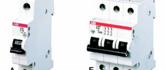
Types of traction substations
Traction substation is primarily divided into two groups:
- Direct current.
- Alternating current.
The first of these options includes equipment designed for 6-220 kV. In this case, power is supplied via overhead and cable power lines. In the case when the voltage is below the threshold of 110 kV, a reduction is required; accordingly, the electricity first goes through the stage of reducing the value of the electrical parameters with the participation of a transformer.
In other situations, the energy is sent directly to the distribution board. device. A multi-type AC traction substation is by and large similar to equipment of this kind operating on direct current, with the only exception being the absence of a converting unit for rectifying the electrical characteristics.
Why is a traction substation needed?
Traction substation of different types is also found in other designs, the division is carried out according to the intended purpose of the transport:
- Equipment for the railway. Available in the following variants:
- Support – can act as a power source for other installations;
- Dead-end – receives electricity from a nearby substation;
- Intermediate - powered by two nearby installations.
- Traction substations for trams and trolleybuses. Equipment of this type also exists in several versions:
- With the need for the participation of service personnel;
- Fully automated;
- TP for trams and trolleybuses, which do not require personnel to operate the equipment and are remote-controlled equipment.
- Installations for the metro. The following types of such equipment are distinguished:
- Traction;
- Decreasing;
- Traction-lowering.
It will be interesting➡ Necessary conditions for parallel operation of transformers
In the first case, a traction distribution substation is presented, powered by city power grids. The second of these options involves receiving high current from the traction unit, which is subsequently reduced to a level of 400-230 V, which is sufficient for power and lighting devices.
Transformer substation.
Specifications
Traction substations for trams, metro and trolleybuses and railway transport have a number of parameters according to which the required option is selected. By the way, if we compare them with equipment such as STP pole substations, which are powered by alternating current and are represented exclusively by a dead-end design, the range will be very wide, which makes the choice somewhat difficult.
To navigate a large number of designs, you need to clearly understand what loads will be placed on equipment of this type, according to which the equipment parameters are determined:
- the value of resistance and voltage on the buses where the rectified current is supplied;
- the traction substation of the metro, railway and other electric transport is characterized by internal resistance, as well as the resistance of the suction feeder and smoothing unit; using these values, you can obtain the resistance value of the entire installation by summing them up;
- Metro and Russian Railways traction substations differ in the number of transformers and switchgear used in the design. devices;
- the voltage of the entire installation is a calculated value and is determined from the formulas;
- short circuit power.
For comparison, the defining parameters for equipment such as pole-mounted transformer substations are: total power, as well as high and low voltage values.
High power traction substation.
Design Guidelines
Transformer power alone is not enough to properly design an installation. A whole list of parameters that affect the operation of the equipment should be taken into account. These include the following:
- The amount of voltage and resistance on the buses into which current is supplied.
- The substation itself has a certain level of resistance, as well as the resistance of the feeder, smoothing unit. When choosing an installation, the total amount of this parameter must be taken into account.
- The design can use a different number of transformers and distributors. When choosing, take into account the operating conditions of the equipment.
- Using generally accepted formulas, it is necessary to calculate the total value of the required installation voltage.
- The short circuit power is also taken into account.
In most cases, the total power of the equipment, as well as low and high voltage indicators, are taken into account.
Structure
The description of the typical circuits of the presented devices is quite complex. However, common features can be identified. The connection in the system is made in accordance with the characteristics of the transport for which the unit is used.
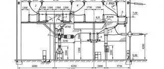
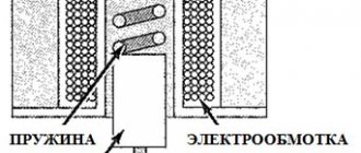
The distributor consists of three blocks. The first contains a device that receives high voltage, the second compartment contains a transformer, and the third contains an output for electricity with specified characteristics. There is only one switch. There is a disconnector at the input.
The connection of the primary windings is carried out according to the star circuit. The zero phase must be grounded. The secondary windings are connected in the form of a triangle. One of the phases is grounded and connected to the rail. The metro has a special contactor for this purpose. This rail is intended solely for relieving the stress of an electric locomotive.
The other phases supply current to the two overhead cables. They are sometimes used to supply electricity to other consumers, but mainly traction substations provide power to trolleybuses via overhead wires. For a tram, this process involves one overhead wire and one ground rail. In most countries of the world, the voltage for such a network is 550 V.
Substation power supply
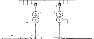
The traction substation must provide an uninterrupted supply of electricity for vehicle movement. Therefore, many of these units are powered from two autonomous networks at once. In this case, a single-line diagram of a traction substation can be used or using two backup lines to another power source. It is also possible to supply power via jumpers between individual substations.
If the option of two separate lines is used, each of them must be designed for the maximum load of the unit. Redundant communications must be able to withstand the total load of the connected stations.
Previously, a radial circuit was used to power subway networks. It is complex and expensive. It requires too much cable. They refused it. Today, only the above schemes are used. Lines and jumpers allow you to combine equipment into separate groups. If one device inside it fails, other units take over its functions.
Also, when carrying out routine maintenance of units, all operations will be easier, without causing the system to stop. In this case, it is possible to de-energize only one unit. Other devices will ensure the operation of the line. This approach to routine repairs greatly simplifies the work of personnel, making maintenance less expensive.
Use of traction substations
The purpose of the traction substation is as follows: to convert and distribute electric current for the purpose of servicing electric vehicles. Substations are divided according to the type of electric current supplied to the contact network - direct and alternating - depending on what type of electric transport is used: electric locomotives of surface railways, subways, trams or trolleybuses. A traction substation can provide electricity to other consumers, not just the railway.
A traction substation can be stationary or mobile. Mobile ones are used quite rarely. The distance between traction substations with direct current in the contact network, they are erected in increments of ten to fifteen kilometers. The distance varies depending on the required power, which depends on the tension in the movement of trains and the terrain.
The traction substation is powered from power lines laid over the air on supports, or through a cable network. The external voltage is reduced by the transformer and transferred to the rectifier, from which electric current is supplied to the contact network. Currently, energy recovery is widely used on electric locomotives and other types of electric transport. When braking, electric locomotives, trolleybuses, trams - consumers of electric current, turn into its source. Electric motors become generators and transmit electric current to the contact network, thereby absorbing the kinetic energy of movement and providing braking for electric vehicles.
Substation contact network.
An inverter is used to flow the current back into the power grid. They automatically turn off the rectifiers as soon as the vehicle braking in recuperation mode begins to produce current. On the railway, the nominal voltage level is considered to be 3300 Volts, in subways 825 Volts, in the contact network of trolleybuses and trams 600 Volts.
AC substations differ from similar DC substations in the absence of a rectifier; a step-down transformer supplies current directly to the contact network.
The distance between traction substations that use alternating current is higher than for stations using direct current - up to fifty kilometers. And the voltage that electric vehicles remove is 27.5 kilovolts. Power supply from an external network for them ranges from 110 to 220 kilovolts. The connection diagram of the primary windings of the step-down transformer of such stations is a “star” with a grounded zero phase. The secondary windings are connected in a delta pattern.
One of the phases is grounded and connected to a rail, which serves as one of the contact wires for the electric locomotive. In the subway, this is a separate contact rail, which serves solely to relieve voltage from the subway electric locomotive. The other two phases supply current to two overhead wires on different paths and are also used to supply other electrical consumers.
There are quite a lot of the latter near railways. This includes automation that controls the movement of trains, signaling devices, communications, lighting of platforms and station buildings, their heating and much more. Traditionally, in many areas, the railway power supply system is the only way to supply voltage to populated areas. Therefore, the traction substation is not only used for electric transport, but also supplies populated areas and other consumers with electricity, meeting their needs.
Power lines.
The traction substation and their groups provide service to ground, mainly urban, electric transport - trolleybuses and trams. They convert current from external networks into direct current and transmit it to contact wires or rails. For trolleybuses there are two contact overhead wires, for trams there is one overhead wire and a rail. The voltage used in most countries is 550 Volts.
It will be interesting➡ What are isolation transformers
A traction substation can be remote-controlled, fully automated, or have service personnel. Most often, personnel are present at small stations in small cities. Where the creation of automatic control systems is not economically feasible.
Or, on the contrary, at large traction substations, whose value is too great to have the risk of shutting them down. Often, personnel are present only at one of the traction substations, from where other stations included in the overall system are remotely controlled. The presence of personnel does not exclude automatic control. In this case, the person is assigned the role of an observer-controller who can intervene in the operation of the substation in emergency cases requiring decision-making and in emergency situations.
How does a traction substation work?
Fully automated stations are used where the intensity of train traffic is low, and the stop should not entail far-reaching consequences in terms of safety. The most reliable and economical control system is remote. A traction substation can be single-unit or multi-unit. Single-unit ones are used where a centralized supply of electricity is not required, on branches. They are quite rare because they do not provide a reliable supply of electricity. If the unit fails, the entire network served by the substation is de-energized. Therefore, two-unit substations are most often used. There are both three-unit and four-unit ones.
The presence of several units significantly increases operational reliability. When one unit fails, the second one turns on, which ensures uninterrupted operation. Also, the presence of more than one unit gives flexibility to the work at times of maximum load. Combining several substations into a single group controlled from one center makes it possible to make them interchangeable, reduces the cost of construction and operating costs.
Interesting read: How to solder aluminum with your own hands.
Since the main condition for the operation of a traction substation is uninterrupted operation, they are all powered simultaneously from two different external networks. Power supply can be carried out via separate lines, or from one using the main and backup lines to another substation; the option of connecting with jumper cables between substations is possible.
When using two separate lines, both must be designed for the maximum load of the substation. The backup connection must simultaneously withstand the load of the connected stations; the connection with a jumper cable must withstand one. Scheme number two is most often used in the metro, as it is quite reliable, economical and easy to manage.
Previously, when the construction of the metro in the country was just beginning, a radial line design was used to power substations from city networks. However, such a scheme is quite complex; it involves many cables and cells. Therefore, it was soon abandoned. Now powering is done using lines and jumpers. This ensures the consolidation of substations into separate groups. If one of the step-down transformers in the group fails, the others redistribute its load.
Number of units
At power supply points for surface and underground transport, installations with different numbers of devices are used. There are both single-unit and multi-unit structures. The first type is used on branches where there is no need to provide centralized supply. The rationale for their use is questionable, since they do not provide high power reliability. If the unit fails or requires maintenance, the entire line will be de-energized. Therefore, such installations are used quite rarely.
Much more often you can find two-unit power supply units. There are substations with three or four transformers. This significantly increases the reliability of the line. They ensure uninterrupted power supply even in the event of failure or maintenance of one unit.
When the load increases to the maximum, multi-device circuits are highly flexible. This approach makes it possible to reduce the cost of construction and operation of equipment.
Having considered the features and types of traction substations, one can assess the importance of their correct selection and operation in urban and state transport networks.
Power plants
In the Soviet Union, two electric traction systems are currently used - direct current with a traction network voltage of 3 kV and single-phase alternating current with a traction network voltage of 25 kV (for voltages on the buses of traction substations for these systems, see Table 1). Recently, a modification of the 25 kV system has become widespread - the 2X25 kV system, which, with the same rolling stock, provides a significant improvement in the characteristics of traction power supply. Below are the main differences of this system. In connection with the widespread electrification of railways, characteristic solutions have now been determined for the implementation of power supply circuits for traction substations. These decisions are recorded in a special instruction of the Ministry of Railways and the Ministry of Energy, which provides recommendations for connecting traction substations to 110 or 220 kV overhead lines running along the route of the electrified railway. Traction substations are connected to such overhead lines according to a simplified scheme without power switches or with a minimum number of them (usually one). Every 100-120 km for 110 kV overhead lines and 130-170 km for 220 kV overhead lines, so-called support substations with switches on each supply line must be built. It is advisable at such a substation to have an additional input from the power supply center of the power system in order to maintain voltage in the overhead lines supplying energy to the traction substations. Where DC traction substations are located near regional power system substations, traction substations can be powered at a voltage of 35, 10 or 6 kV. In this case, the connection between the traction and regional substations must be made by several lines, so that if one of them fails due to an accident, the others can provide the maximum load of the traction substation. When placing traction substations in a built-up area, it is allowed to make BJI 10 and 6 kV cable. Due to the high power of AC traction substations, voltages below 110 kV are not used to power them. Therefore, when placing such a substation near a district one, it is recommended to combine them on one site. In Fig. Figure 7 shows an approximate diagram of an external power supply for an electrified railway line. The traction power supply system includes the following elements: traction substations, supply and suction lines, traction network and auxiliary devices (sectioning posts, switch grouping points at docking stations, parallel connection points, suction transformers). The designs of these devices are very diverse and depend on the adopted current system, the volume of transportation work of the railway and its technical equipment. Schematically, the elements of the traction power supply system are usually depicted on the power supply and sectioning diagram of the contact network of the electrified section. The section of the contact network between two traction substations is called the double-sided power supply zone. If an area is fed by only one traction substation, it is called a cantilever power zone. If there are parallel connection points (PCP) on two track sections, one each between the substation and the sectioning station, the power supply circuit is called parallel, and in the absence of PCP - nodal. Traction substations. Traction substations feed the traction network (contact network and running rails) and convert the three-phase alternating current of the supply overhead lines into direct current with a voltage of 3300 V (with direct current traction) or into single-phase alternating current with a voltage of 27,500 V (with alternating current electric traction). Feeding and suction lines. Feeding lines are designed to transmit traction current from substations to the contact network, and suction lines are designed to return current from the running rails of the railway track to the traction substation. Supply lines for railways are usually carried out overhead on metal or reinforced concrete supports. The design of such lines is similar to the design of three-phase BJI, however, the supports are used more powerful, since a significant number of wires are suspended on them - two or three lines, each of which can consist of three to five wires. With an alternating current system, in some cases it is possible to use standard 35 kV overhead line support structures for supply lines. The range of wires and insulators used is the same as for general purpose overhead lines. For a 27.5 kV overhead line, the same number of insulators is taken as for a 35 kV overhead line. The overhead contacts of individual tracks are powered by independent supply lines (feeders). The suspension of each track to the right and left of the traction substation is also fed by a separate feeder. If the station where the traction substation is located has less than five tracks, its contact network is powered by overhead feeders; if there are more than five tracks, a special “station” feeder is usually built at the traction substation to power the station contact network. At large stations, separate feeders are often used to supply a network of large parks. Power supply to the grouping points of docking stations is carried out, as a rule, by separate feeders connected in a ring. The suction lines are also mostly overhead, however, if the traction substation is located near the tracks in a built-up area, cable lines can also be used with a DC system. For a 27.5 kV AC system, in many cases the rails of the access track of the traction substation are additionally used as suction wires. The suction wires are not connected directly to the running rails, but to the zero point of the automatic blocking track chokes. This ensures the normal operation of railway automatic blocking and centralization devices (SCB). Suction wires are usually connected to the tracks closest to the traction substation. At docking stations for suction, the access track rails, as a rule, are not used. Traction network. The contact network, together with the running rails, forms a traction network designed to transmit current from the substation to a locomotive moving along the railway track (electric locomotive, motor car), and drain the current back to the substation. The running rail is used as a return wire. The contact network has a complex design that ensures the transfer of current from the wire to the pantograph of the locomotive at high speeds of the latter; sufficient mechanical stability of the position of the wire relative to the track axis during atmospheric changes (temperature, wind, ice); mechanical strength of wires abraded by fast-moving pantographs; maintaining vertical dimensions between wires and rails; safety for the population, passengers and service personnel. The contact network consists of a catenary, supporting and supporting structures. Contact suspensions are used of various types depending on the train traffic conditions (profile and layout of the line, speeds). The most widespread on railways are the so-called chain suspensions, consisting of a support cable and a contact wire 2, connected by strings 3. If the current of one locomotive can exceed 1200-1400A, two contact wires are suspended from the support cable, along which the pantograph slides simultaneously. To compensate for large voltage losses or reduce heating of the wires, the chain suspension is often supplemented with reinforcing wires, suspended separately on the same supports. The supporting cable, contact and reinforcing wires are electrically a single conductor. In order to maintain the required vertical dimension of the contact wire, tension is created in each suspension section (the so-called anchor section) with special weights 5, suspended from the wires at the end of the section. If the loads are suspended only from the contact wires, the suspension is called semi-compensated, but if they are suspended both from the wires and from the supporting cable, the suspension is called fully compensated. The weights compensate for changes in wire length under the influence of changes in ambient temperature. Supporting structures are supports and their foundations 7. Currently, most supports are made of reinforced concrete. In some cases, metal, and even less often, wooden supports are used. Supports are classified according to their load-bearing capacity, determined by the bending moment at the point where the support is embedded in the ground or connected to the foundation. In addition, reinforced concrete supports are divided into solid ones, embedded in the ground with part of their trunk (sometimes using crossbars that increase soil resistance) | and separate, strengthened in the so-called glass foundations. Metal lattice supports used at stations are always installed on foundations. The foundations of all supports are made of reinforced concrete elements. Supporting structures include consoles, brackets, flexible and rigid cross members and some other elements. Consoles 9 are used for suspending wires to supports above the axis of the track along which the locomotives move. The type and size of the consoles depend on their purpose, the size of the installation of supports and the presence of curved sections of the track. Fixing brackets, which also have several varieties, are designed to clearly fix contact wires above the axis of the track 6 using special elements (clamps) 8. In addition, they are used to create so-called zigzags of wires, i.e., displacement of the wires from the axis of the track. Zigzags of wires are necessary to ensure uniform abrasion of the entire surface of the locomotive's pantograph, and not just one narrow strip of it. Flexible crossbars consisting of; wires attached to supports across the track are used to suspend the contact network over many tracks at once, for example at stations where there are more than eight tracks. Rigid crossbars 4 (metal trusses) are designed for the same purpose when suspending a network over two to eight tracks. Running rails, used to return traction current from the locomotive to the traction substation during electric traction, are equipped with rail connections, which are installed between individual rail links to reduce resistance at the joints. At stations, connections are also made between the rails of individual tracks. Sectioning of the contact network. Typically, they provide for sectioning the contact network of the power zone, i.e., dividing it with special disconnectors into sections, each of which can be switched off (de-energized) without depriving the remaining sections of voltage. Sectional disconnectors also serve to supply backup power to individual sections. Sectioning of the contact network must provide power from one feeder to two paths or two directions of one path using longitudinal and transverse normally disconnected disconnectors on the feeder lines of substations and sectioning posts; separation of the station contact network from the railway contact network with the installation of an additional transverse disconnector used for redundancy; allocation of the contact network of groups of tracks at stations with large track development. At the same time, at very large stations, a special sectioning post is sometimes installed, from which individual parks, depots and equipment units receive power through their lines through power switches. Such a post is usually powered from a substation by a special feeder line. A significant part of sectional disconnectors are equipped with remote control. With alternating current, it is necessary to specially isolate the contact networks powered from various feeders of the traction substation. For this purpose, so-called neutral inserts and sectional insulators, shown schematically in the figure, are used. At stations where lines electrified at two different types of current are connected, a more complex sectioning scheme is implemented, which ensures automatic dependence between the switches that supply power to individual sections of the network and routing devices for electrical centralization of switches. Each section at such a station has a special feeder that feeds it from the switching point. If the coupling is performed using a dual-power electric locomotive, then such a complex sectioning scheme is not required and it is performed as usual as for an alternating current system. Assistive devices. Auxiliary devices of the power supply system are designed to improve the operating conditions of the main traction devices. Sectioning posts allow, in the event of a short circuit, to electrically divide a section of the traction network between two substations into independent sections and thereby improve the conditions of protection against short circuit currents in the contact network. Parallel connection points serve for electrical connection of contact networks of different tracks of two track and multi-track sections. Such a connection reduces voltage and energy losses in the network, while at the same time allowing it to be divided in the event of an accident in the contact network of one of the paths. Switch grouping points are installed at those stations where two traction systems are connected - direct current 3300 V and alternating current 27.5 kV. To change locomotives at such stations, each group of tracks can, if necessary, be supplied with one or the other voltage. The voltage change is carried out by the station duty officer from the electrical centralization post by remote control of the switch or automatically, depending on the route being created. Switches are grouped in groups of 6-9 pieces. At each such station, several switch grouping points are installed. At the grouping points, a block is also installed to protect against the entry of one voltage into the network of another voltage, the so-called ZSS block (protection of the docking station). Suction transformers are used in some areas electrified using a 2/.5 kV AC system to reduce the influence of contact network currents on communication lines and electrical lines of other voltages. In addition, these transformers reduce stray currents and their generation in metal pipelines or other structures laid in the ground. The current returning from the locomotive to the substation, due to the relatively high resistance of the rails and their poor insulation from the ground, flows largely along the ground. If there are metal objects in the ground, it flows along them, and sparks occur in places of poor contacts, which can cause an accident (for example, on oil or gas pipelines). Suction transformers must create such a potential difference between the rails and the ground that would significantly (in practice by 85-90%) reduce the currents flowing in the ground. To increase the conductivity of the track circuit with suction transformers, a return wire is often used, which is suspended on the supports of the contact network. Since suction transformers greatly reduce the difference between the current in the contact network and the return current (in the rails or in the rails and the return wire), the inductive effect of such a system of conductors on communication lines and other electrical communications is much less than in the absence of such transformers.