In industrial power lines, which include powerful transformers, electric pump motors, and powerful units, various emergency situations can occur. As a result of such situations, electrical equipment breaks down. Each network component has its own maximum current rating. If this current increases, then penetration of the insulating layer occurs, as well as melting of the wiring. In this case, the entire power line becomes faulty. In order to protect expensive electrical equipment, it is recommended to install an overcurrent relay. Such a device can protect electrical equipment from short circuits and increased loads.
Overcurrent relay device
Purpose and classification of overcurrent relays
The relay is capable of monitoring the current indicator in a specified section of the electrical circuit. If this indicator is exceeded, the relay is capable of opening the circuit or giving a signal in the form of light or sound about a fault in the power line.
According to the principle of purpose, relays are available for sockets, lighting and for high-power electrical appliances.
Socket devices are used for electronic devices that react strongly to sudden changes in current and voltage. At the same time, expensive devices are protected from short circuits, as well as sudden increases in voltage in the power line.
Devices designed for high-power electrical appliances monitor current levels, while protecting magnetic starters, electric motors, controllers, transformers and other elements of the electrical network.
Overcurrent relays are divided into primary and secondary measurement types.
The first type of measurement is intended for electrical networks with voltages up to 1 kV, and it is connected directly with its terminals.
Another type is connected via a current transformer, while measuring the secondary current. The transformer changes the current towards the lowest value that is appropriate for a given device. Therefore, in such an electrical network it is possible to operate a device with a small current indicator. This type is used in high voltage circuits.
Secondary measurement types have subgroups: electronic, electromagnetic, as well as differential and induction types.
Relay selection criteria
There are many models from different manufacturers on the market, but the choice is determined by the technical specifications based on the operating conditions of the equipment. First of all, the magnitude of the current load is taken into account; modern products provide several mounting options, on flat surfaces and DIN rails in distribution cabinets. Some samples have a large number of options and advantages:
- small dimensions,
- easily adjustable wide range of threshold values,
- light and sound indication when triggered;
- Digital indication of the values of various parameters on a liquid crystal or LED display.
When choosing a product, it is necessary to take into account the placement conditions, climatic factors and the degree of protection of the relay. Depending on the model and the number of options, a relay can have a large number of technical characteristics, but there are basic ones that necessarily characterize all current relays.
Operating principle of overcurrent relay
The basis of the operating principle of the device is its sensitivity to an increase in the current indicator in the protected power line. If the current increases, the contacts switch, thereby disconnecting the electrical equipment from the circuit. When this parameter decreases and equals the set value, the elements are closed again and production resumes.
Modern overcurrent relay
Features of relay production depend on their classification.
The operating principle of the differential type is formed by comparing the current characteristics before and after the load. Often this load is a transformer. In good condition, the current indicator before and after the load is equal to each other. In the event of an emergency, an imbalance occurs and equality is violated. The relay instantly closes contacts and sends signals to disconnect the damaged area of the electrical circuit.
The protective device, which is of an electronic type, is made on the basis of semiconductors. Their advantage is that they remain operational in vibrating conditions.
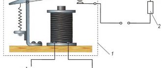
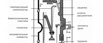
The design of the electromagnetic device includes a magnetic circuit bracket. A tube with a coil on top is screwed into the bracket. And in the tube there is an anchor that moves along it. In this case, the response rate of the device depends on the location of the anchor.
The setting current indicator is adjusted by moving the location of the bracket. Next, the bracket is secured with a screw. When the device is triggered, the contacts open and the armature moves to the upper position. When the current returns to its original value, the armature moves to the lower position, and the contacts are locked.
Design and principle of operation
There are many types of electronic safety devices. Most of them have a standard design. The device consists of the following elements:
- electromagnet;
- anchors;
- contacts;
- taps through which the device is connected to the network;
- springs.
The operating principle of a current relay is that when the device is connected to the network, the coil receives electrical energy. Next, through the armature and the metal core, contacts are intertwined. At the same time, the contacts of all devices that were included in the device circuit are closed. In this case, the current may not be supplied at all, and if it is supplied, it will be uneven. In this case, the contacts of the devices rise and the circuit opens.
You might be interested in Hand press pliers
The effect of the protective device itself depends on its design features and purpose.
For example, a solid-state device contains additional power switches using thyristors and triacs, so it is considered more efficient. The throughput of the device is important.
Pros and cons of overcurrent relays
The device has a number of advantages:
- the presence of endurance to high pulse voltages and interference that are formed as a result of lightning or during switching in high-voltage electrical equipment;
- a slight drop in voltage at closed contact connections, without heating them;
- resistance to increased switching loads;
- excellent insulation between the coil and the contact group;
- low cost of the device.
At the same time, we can list the disadvantages of the relay:
- low productivity;
- limited resource of electromechanical characteristics;
- When locking and disconnecting contacts, interference is generated;
- In a DC network, failures are possible when switching consumers with high voltage.
Connection diagrams
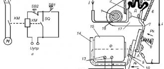
The simplest and most common method of protection is direct connection to the circuit of an electromagnetic current relay.
This diagram shows how an ammeter is connected sequentially into a phase wire gap to monitor the amount of current flowing, then an electromagnetic relay coil and a load.
The neutral wire is connected to contact No. 11 of the relay switching, which in the normal state is closed with contact No. 12, from which the neutral wire goes to the load.
When the threshold current value is reached, the coil core drives the opening mechanism of contacts 11 and 12, after which the load is de-energized. Please note that the coil has three terminals, the winding is divided into two parts, this is one of the methods for adjusting the trigger current threshold value. If the load is connected to contact E2, the threshold current value will increase by 2 times.
An example of connecting a transformer-type current relay to a circuit
In high-voltage networks, the primary winding of the transformer is connected in series to the load, the secondary winding with reduced voltage and current powers the relay coil with the core. Further work is carried out as in the previous case. When triggered, contacts 11 and 12 open.
Very often, such protection circuits are used to protect the windings of powerful, expensive electric motors..
In circuits with high current shutdown thresholds, the relay coils have a small number of turns and a thick winding wire.
The photo shows a relay coil REO-401, capable of passing currents up to 100A. The winding has only 6 turns of copper wire with a cross-section of 6-8mm2
Main technical characteristics
- Nominal (operating current) in the coil;
- The current in the coil is permissible for long-term operation;
- The coefficient of return of contacts to their original state after operation (the ratio of the operation current to the contact release current), usually 0.6 - 0.8;
- Operation current threshold;
- Maximum permissible current on the closing contacts;
- Current permissible during long-term operation on switching contacts;
- Power consumption by the coil winding in normal mode;
- Power increase in % after triggering;
- Type of current: alternating or direct;
- Operating voltage;
- Weight, dimensions, weight and other parameters depending on the model and its purpose.
Tip No. 2 When installing a relay or changing the load, in addition to the threshold operating current, do not forget to set the appropriate shutdown time. Otherwise, if there is a long interval before shutdown, the load elements may burn out.
Let's look at the technical characteristics using the example of products from the RT-80...90 series.
| Modification of the RT model | operating currents, A | ||
| fixed operating currents of the induction element, A | response time, s* | ||
| 81\1 | 10,1 | 4.1AA* 5.1AA* 6A* 7A* 8A* 9A*10A | 1* 2* 3* 4 |
| 91\1 | |||
| 81\2 | 5,1 | 2A* 2.5A* 3A* 3.5A* 4A* 4.5A* 5A | |
| 91\2 | |||
| 82\1 | 9.9 | 4A* 5A* 6A* 7A* 8A* 9A* 10A | 4* 8* 12* 16 |
| 82\2 | 5,1 | 2A* 2.5A* 3A* 3.5A* 4A* 4.5A* 5A | |
| 83\1 | 9.9 | 4A* 5A* 6A* 7A* 8A* 9A* 10A | 1* 2* 3* 4 |
| 83\2 | 5,1 | 2A* 2.5A* 3A* 3.5A* 4A* 4.5A* 5A | |
| 84\1 | 9.9 | 4A* 5A* 6A* 7A* 8A* 9A* 10A | 4* 8* 12* 16 |
| 84\2 | 5,1 | 2A* 2.5A* 3A* 3.5A* 4A* 4.5A* 5A | |
| 85\1 | 9,9 | 4A* 5A* 6A* 7A* 8A* 9A* 10A | 1* 2* 3* 4 |
| 95\1 | |||
| 85\2 | 5 | 2A* 2.5A* 3A* 3.5A* 4A* 4.5A* 5A | |
| 95\2 | |||
| 86\1 | 10 | 4A* 5A* 6A* 7A* 8A* 9A* 10A | 4* 8* 12* 16 |
| the current in the coils is permissible for long-term operation in % of the rated one. | For all modifications of RT (80…90) | 110 | |
| 110 | |||
| Minimum return rate | 0.8 | ||
| For RT (81...84 and 91) the closing current with a supply voltage of 24-250V is independent of direct or alternating current in the circuit. Opening is carried out by the contacts of another switch | 5A | ||
| Increase in power consumed by the coil after activation in % | 15 | ||
| Trip current | ~ current | 2 | |
| - current | 0.5 | ||
| For RT modifications (81...84 and 86) currents when opening or closing contacts in signal circuits 24 - 250V, A | ~ current | 1 | |
| - current | 0.2 | ||
| Power consumed in current mode equal to the set current | for RT80 | 10A | |
| for RT90 | 30A | ||
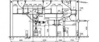
Dimensions of current relays of the RT80...90 series.
Description of the RMT 101 model
This relay is of modern design, multifunctional and is in great demand among consumers; let’s consider its technical capabilities.
Functional purpose
The relay is used to control the load current throughout the entire operating time of load devices with single-phase power supply. Current measurement limits are from 0 to 100A, the device turns off the load when the set threshold current value is reached. Each player, coming to the gaming hall, is looking for a way to save a little and reduce the cost of playing. He registers and receives a profitable welcome capital - no deposit bonuses from the casino, which come in the form of real funds or free spins. You can start the gameplay without an initial investment - use the first reward from the club for your own benefit. In order for it to be credited to your account, you need to register on the casino website, indicate and confirm the user’s personal data, and then make a request for the welcome capital. The load is connected through the relay switching contacts with a power consumption of no more than 1.75 kVA. current loads above this value up to 20 kVA are connected through magnetic starters with contacts capable of withstanding a load of the corresponding power.
Relay controls allow the user to manually set:
- Current thresholds;
- Shutdown delay time;
- Restart time after triggering;
At the same time, in addition to protection functions, the product has additional functions:
- Digital ammeter measures and displays load currents;
- Limitation of current consumption;
- A relay with load selection priority is used.
The built-in current transformer allows you to measure the current value without breaking the circuit; LED indicators on the front panel display the state of the relay and within what limits the load current is.
Main technical characteristics
| Power supply single-phase AC voltage | 220V |
| Network voltage frequency | 50 Hz |
| Current measurement range | 0-100A |
| Measurement error | 1% |
| Switching time adjustment interval | 0 – 900 sec. |
| Shutdown time adjustment interval | 0 – 300 sec. |
| Maximum switching current | 8A |
| Maximum permissible voltage | 400V |
| No load power consumption | 3.5W. |
| Wear resistance of switching contacts: - at a load of 8A - at a load of 1A | 100 thousand operations; 1 million. |
| Cross-section of connected wires in the network | 0.5 – 2mm2 |
| dimensions | 90-52,6-69,1 |
| fastening | On din - rail |
The design allows the product to function in any position in space relative to the surface of the earth.
Operating principle of RMT
Using the example of the operation of the REO-401 relay, you can clearly understand the principle of operation.
Main design elements of the REO-401 current relay
The coil is connected at its ends to an open circuit; when current flows through the winding, an electromagnetic field is induced, which, when the set current threshold is reached, pushes the rod out of the tube in the center of the coil. The core presses on the rod, which moves the closing plate, compressing the spring, after which the circuit opens. As the current drops, the spring pressure on the plate weakens, and the plate again closes the gap in the circuit. Read also the article ⇒ Voltage relay.
The magnitude of the response threshold in this embodiment is regulated by the depth of immersion of the tube with the core into the cylindrical hole of the coil. The tube is screwed in or out of the coil, thus adjusting the response threshold. In some designs, the tube moves freely inside the coil and is secured with a clamping screw.
This example shows the classic version, where the principle of operation of the relay is clearly visible; there are many models with other designs and additional functions. The basic principle in all options is the same: when the set maximum current threshold is exceeded, the relay disconnects the circuit from the power source.
Tip No. 1 It is recommended to install the current relay in a distribution cabinet; this is convenient and simplifies the process during repair or replacement.