A Solid State Relay (SSR) or Solid State Relay (SSR) is an electronic device that performs the same functions as an electromechanical relay, but contains no moving parts. Commercial solid state relays use semiconductor device technologies such as thyristors and transistors.
That is, instead of moving contacts, TSRs use electronic semiconductor switches, in which the control circuits are galvanically isolated from the power switched circuits. Fortunately, now there are no problems purchasing switching field-effect transistors. Thus, to build a solid-state relay, we need a MOSFET (Metal-Oxide-Semiconductor Field-Effect Transistor) transistor, the Russian equivalent of the term is MOS transistor or insulated gate field-effect transistor, and an optocoupler. On the pages of the site there are articles devoted to transistor switches with optical isolation - “AC transistor switch”
This article discusses a key for switching alternating current. Using SMD components according to this scheme, it is possible to produce an alternating current SSR. Some of the parts are mounted on a printed circuit board, which is attached to an aluminum support. Transistors are mounted on the substrate through mica spacers. It is better to take capacitor C1 either tantalum or ceramic. Its capacity can be reduced. Another article - “Transistor switch with optical isolation”
In this circuit, bipolar transistors of different structures are used as switching transistors.
There is another circuit of a galvanically isolated switch on a mos-transistor with protection against the maximum load current. It was discussed in the article “Powerful DC switch on a field-effect transistor”
All this is good if the voltages with which SSRs implemented on MOSFETs operate allow these field-effect transistors to be controlled. But what about voltage switching, for example 3.3 volts. This voltage is clearly not enough to open the field effect transistor. We need some kind of converter capable of raising the control voltage to at least five volts. Using a classic pulse converter for relays is too cumbersome. But there are other converters - optical, for example - TLP590B .
Definition
A solid-state relay is an electronic device, one of the types of relays in which there are no moving elements. The product is used to supply current or break a circuit by external control (by applying a small voltage).
A solid state relay (abbreviated as SSR) has a sensor inside that responds to the supply of a control signal. In addition, the product contains solid-state electronics, including a switching circuit capable of switching large I.
The device can be installed in AC and DC circuits and is often used as a conventional relay. The main difference is that the SSR has no mechanical contacts.
Indications for use
Solid state relays are recommended for use in cases where standard devices cannot cope with their obligations. For example, when they melt or burn during the switching process.
With the help of TSR, the reliability of the circuit and the timely supply of voltage to the load are guaranteed. Unlike simple devices, it is not a problem for SSRs to cope with an inductive load.
In addition, a solid-state device should be used when there is a shortage of space during the installation process and when there are high requirements for circuit reliability.
Triac optocouplers | Techniques and Programs
One of the areas of application of optocouplers is contactless control of high-voltage circuits operating on alternating or pulsating current. For these purposes, devices are manufactured based on a photothyristor (triac - two photothyristors in one housing). Its structure and operation in circuits is similar to conventional thyristors (can be in one of two stable states). In addition to directly controlling a low-power load, such elements can be used to trigger (turn on) more powerful thyristors and triacs.
The main parameters of the most common optocouplers of this class are given in table. 8. Some of them have a built-in control circuit for detecting zero - ZCC (Zero Crossing Control), which ensures that the triac is turned on only when the supply voltage phase passes through “zero”. This implies that the switch is turned on at a voltage of about 5...20 V (due to the physical principles of operation at zero, it is impossible to turn on such elements, unlike transistors).
Table 8. Basic parameters of triac optocouplers
Note on the table
UpK - maximum permissible peak voltage between input and output; URMS - maximum permissible insulation voltage (rms value).
End table 8
Information on the interchangeability of single-channel triac optocouplers from different manufacturers is given in Table. 9.
Table 9. Options for replacing triac optocouplers
| Basic type | Complete foreign analogues (domestic version of the analogue) | Frame | Output Features |
| MOS8YU | TLP532, TCDT1110, CNY17F-2, PC714V | DIP-6 | |
| MOC811 | TLP632, IL2B | DIP-6 | |
| MOC3020 | TLP3021, K3020P, BRT12H, OPI3020, MCP3020, GE3020 | DIP-6 | |
| MOC3021 | TLP3021, GE3021, ECG3048, OPI3Q21, MCP3021, GE302t | DIP-6 | |
| MOC3022 | TLP3022, OPI3022, MCP3022, GE3022, (AOU163A)________ | DIP-6 | |
| MOC3023 | TLP3023, OPI3023, MCP3023, GE3023_ | DIP-6 | |
| MOSZOZO | TLP3041, ORTOBZO | DIP-6 | There is a ZCC scheme |
| MOSZOE1 | TLP3041, ORTOBZO | DIP-6 | There is a ZCC scheme |
| MOSZOE2 | TLP3042, ORTOBZO | DIP-6 | There is a ZCC scheme |
| MOC3040 | TLP3041, TLP3042, ORTOBZO | DIP-6 | There is a ZCC scheme |
| MOC3041 | TLP3042, ORTOBZO | DIP-6 | There is a ZCC scheme |
| MOC3042 | TLP3042, ORTOBZO | DIP-6 | There is a ZCC scheme |
| MOC3043 | TLP3043, ORTOBZO | DIP-6 | There is a ZCC scheme |
| MOSZOBO | TLP3061, ORTOBZO | DIP-6 | There is a ZCC scheme |
| M0c3061 | TLP3061, (AOU179A), ORTOBZO | DIP-6 | There is a ZCC scheme |
| MOC3062 | TLP3062, ORTOBZO | DIP-6 | There is a ZCC scheme |
| MOSZOBZ | TLP3063, ORTOBZO | DIP-6 | There is a ZCC scheme |
Note on the table
It should be taken into account that it is possible to replace optocouplers of a similar structure with better parameters, for example with a higher operating voltage: MOSZOBZ with MOC3083, etc.
When the output triac of the optocoupler is in the open state, the maximum voltage that remains at its terminals can be from 1.8 to 3 V (depending on the current in the circuit). At
Rice. 5. Pin layout and internal structure of triac optocouplers
In this case, the short-term pulse current through the load should not exceed 1 A. In order not to damage the input LED, the direct current through it should not exceed 60 mA (the voltage drop across the LED does not exceed 1.6 V, which is true for all low-power optosimistors).
Where are they used?
Solid state relays are unique devices that do not require special maintenance after installation. The “set it and forget it” principle works here. For example, in simple models, the contact group is cleaned at a certain frequency - usually after a certain number of cycles. If the product is used infrequently, this does not cause problems.
But what about equipment that requires frequent activation—once per second or even more often? An example of such a technique is a machine with solenoid-type valves.
The voltage is supplied through a relay, which has to break up to ten amperes of inductive I. If you install a contact device, it will have to be replaced every 1-2 months. If you install a solid-state analogue, you can forget about it for many years.
Despite the reliability of operation, TSRs require periodic inspection. Basic recommendations in this matter are provided by the product manufacturer. As a rule, we are talking about checking the fact of contact closure, the integrity of the housing and insulation.
Industrial design Siemens V23103-S2232-B302
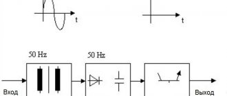
The solid state diagram is shown in the figure:
Using this scheme, you can make a solid-state relay with your own hands quite quickly, without any difficulties. The main thing is to find the necessary components or analogues. The protection can be located either inside the relay housing or separately. Now we need to consider additional devices that need to be used in conjunction with the relay.
Types of solid state relays
SSRs are conventionally divided according to two criteria - the principle of operation and design features. To simplify the classification, we highlight the following options:
- By type of control signal - variable or constant I.
- According to the type of main (switched) voltage - constant or alternating.
- According to the number of phases (for alternating voltage) - one, three.
- According to the presence of reverse - provided, not provided.
- According to the subtleties of the design - on a DIN rail or on a surface.
Types and classification
By installation method
Various models of SSRs are available with mounting on supporting surfaces, printed circuit boards or DIN rails.
Figure 3. Device for installation on a printed circuit board.
To cool the relay, special radiators are used, installed between the support and the block.
For additional protection against overheating, thermal paste is applied to the surface of the device to increase heat transfer by increasing the contact area.
There are models designed to be attached directly to the wall with screws.
For installation in an electrical panel, TTRs with DIN rail mounts are available.
Rail mounting.
To remove excess heat, the relay is attached to the rail through brackets.
By type of switching network switching
The devices differ:
- With a “through zero” regulator. Triggered at zero voltage. Designed for devices with weak inductive, resistive or capacitive loads.
- Instant. Used when sudden operation is required.
- Phase. In such devices, when the resistance value changes, the power at the load changes. It is used to adjust the lighting level in incandescent lamps, or the temperature in heating elements.
By type of operating current
Solid state relays can be controlled by electrical circuits with two types of current:
- permanent;
- variables.
DC switching is used at constant voltages up to 32 volts.
Most operate on alternating currents. Such devices are characterized by instantaneous operation, efficiency and low degree of electromagnetic interference. Operating voltages are 90-250 volts.
By number of connected phases
There are:
- Single-phase, operating in the range of 10-100 and 100-500A, are installed in household appliances.
- Three-phase, 10-120 A, switching voltage on three phases at once.
Single-phase devices are controlled using an analog signal and a variable resistor.
The design of three-phase relays involves reversible operation, providing regulation of several electrical circuits simultaneously.
Three phase relay
To make the correct connection when installing equipment, wires of different colors are connected to the three-phase relay.
Intraspecific differences
In addition to the main classification, it is worth highlighting the differences within the existing types of TTP.
The following types are distinguished:
- THREE-PHASE - capable of conducting currents of 10-120 Amperes simultaneously in three phases.
- REVERSIVE - devices built on the semiconductor principle, capable of operating in circuits with direct and alternating current. In terms of purpose and principle of operation, they are identical to single-phase ones. A prerequisite is the presence of a control circuit that protects the device from false operation. The advantages of solid-state three-phase relays include the ability to operate simultaneously in 3 phases, as well as a long service life. The increased service life is due to the presence of reliable insulation and a well-thought-out control circuit. In the process of using solid-state models there is no noise, sparks, rattling during switching and other negative factors.
- SINGLE-PHASE - products that provide circuit separation when a sinusoid passes through zero. The TSR operates in the following range - 10-500 A. Control is carried out in several ways.
What are the features?
When creating a solid-state relay, it was possible to eliminate the occurrence of arcs or sparks during the process of closing/opening the contact group. As a result, the service life of the device has increased several times. For comparison, the best versions of standard (contact) products can withstand up to 500,000 switching operations. There are no such restrictions in the TTPs under consideration.
The cost of solid-state relays is higher, but a simple calculation shows the benefits of their use. This is due to the following factors - energy savings, long service life (reliability) and the presence of control using microcircuits.
The choice is wide enough to choose a device taking into account the tasks and current cost. There are both small devices for installation in household circuits and powerful devices used to control motors.
As noted earlier, SSRs differ in the type of switching voltage - they can be designed for constant or variable I. This nuance must be taken into account when choosing.
Features of solid-state models include the sensitivity of the device to load currents. To avoid such a problem during operation, it is important to carefully approach the installation process and install protective devices in the key circuit.
In addition, it is important to give preference to switches that have an operating current that is two or three times the switched load. But that's not all.
For additional protection, it is recommended to provide fuses or circuit breakers in the circuit (class “B” is suitable).
Operating principle of the start relay
Despite the large number of patented products from various manufacturers, the operation schemes of refrigerators and the operating principles of starting relays are almost the same. Having understood the principle of their operation, you can independently find and fix the problem.
Device diagram and connection to the compressor
The relay circuitry has two inputs from the power supply and three outputs to the compressor. One input (conditionally zero) passes directly.
The other input (conditionally – phase) inside the device is split into two:
- the first passes directly to the working winding;
- the second passes through the disconnecting contacts to the starting winding.
If the relay does not have a seat, then when connecting to the compressor you must not make a mistake with the order of connecting the contacts. Methods common on the Internet for determining winding types by measuring resistance are not correct in general, since some motors have the same resistance of the starting and running windings.
The electrical circuit of the start-up relay may have minor modifications depending on the manufacturer. The figure shows a diagram of the connection of this device in the Orsk refrigerator
Therefore, it is necessary to find documentation or disassemble the refrigerator compressor to understand the location of the feed-through contacts.
This can also be done if there are symbolic identifiers near the outputs:
- “S” – starting winding;
- “R” – working winding;
- “C” – general output.
The relays differ in the way they are mounted on the frame of the refrigerator or on the compressor. They also have their own current characteristics, so when replacing it is necessary to select a completely identical device, or better yet, the same model.
Closing contacts using an induction coil
An electromagnetic starting relay works by closing a contact to pass current through the starting winding. The main operating element of the device is a solenoid coil connected in series with the main winding of the motor.
At the moment the compressor starts, with the rotor static, a large starting current passes through the solenoid. As a result, a magnetic field is created that moves the core (armature) with a conductive strip installed on it, which closes the contact of the starting winding. The rotor begins to accelerate.
As the rotor speed increases, the amount of current passing through the coil decreases, as a result of which the magnetic field voltage decreases. Under the action of a compensating spring or gravity, the core returns to its original position and the contact opens.
On the cover of the relay with the induction coil there is an “up” arrow, which indicates the correct position of the device in space. If it is placed differently, then the contacts will not open under the influence of gravity
The compressor motor continues to operate in the mode of maintaining rotor rotation, passing current through the working winding. The next time the relay will work only after the rotor stops.
Regulation of current supply with a posistor
Relays produced for modern refrigerators often use a posistor - a type of thermal resistor. For this device, there is a temperature range below which it passes current with little resistance, and above which the resistance increases sharply and the circuit opens.
In a starting relay, a posistor is integrated into the circuit leading to the starting winding. At room temperature, the resistance of this element is insignificant, so when the compressor starts operating, current flows unhindered.
Due to the presence of resistance, the posistor gradually heats up and when a certain temperature is reached, the circuit opens. It cools down only after the current supply to the compressor is stopped and starts skipping again when the engine is turned on again.
The posistor has the shape of a low cylinder, which is why professional electricians often call it a “tablet”
Design features
The solid-state relay is based on an electronic board, which includes three main elements - control and isolation units, as well as a power switch. The following parts are used as power elements:
- For constant I - field-effect transistors, simple transistors, modular elements of the IGBT class, as well as MOSFET transistors.
- For variable I - assemblies based on thyristors, as well as triacs.
Circuit decoupling is provided by optocouplers - products consisting of a light-emitting and light-receiving device. A dielectric having a transparent structure is installed between them.
The control unit is made in the form of a stabilizing circuit that provides optimal current and voltage levels for the light-emitting element. The voltage at the circuit input should be from 70 to 280 Volts.
As for the load voltage, its value is up to 480 Volts. The location of the electrical appliance (before or after the TTR) does not matter.
As a rule, the device is mounted after the load and then connected to ground. With this version of the circuit, it is possible to protect the internal elements from the flow of short-circuit current (it will flow through the grounding wire).
Types of TTP
When assembling solid-state relay circuits with your own hands, you should keep in mind that a variety of components can be used for these purposes. Nothing prevents the person who takes up the job from choosing modern field-effect transistors, for example, characterized by high performance and low power consumption. These elements are controlled only by potentials, providing the ability to switch sufficiently powerful consumers. Field structures such as MOSFETs are capable of switching load circuits whose power reaches tens of kW.
To independently manufacture a solid-state relay, it is possible to select other semiconductor structures capable of controlling power circuits: thyristors, for example, or bipolar transistors. The main thing is that they meet the requirements for the functionality of this circuit and the operating parameters of the elements included in its composition. Everything else depends on the preparedness and attentiveness of the performer.
Operating principle
Knowing the design features of a solid-state relay, it is easier to understand the principle of its operation. Two signals interact in the device - control and controlled, which is ensured thanks to galvanic isolation.
In some SSR models, this function is performed by an optocoupler. The voltage that controls the device is also supplied to the LED.
The glow of the latter enters the photodiode, which leads to the appearance of a current, turning on an MOS or thyristor to control the connected device.
In addition, in the process of creating a circuit, it is possible to use special optoelectronic devices - opto- and photothyristors.
Differences and advantages of solid-state relays (compared to electromechanical ones)
When choosing an SSR, the buyer has a number of questions - why overpay for a solid-state relay, what are its advantages over standard electromechanical devices. Let's highlight the main advantages:
- Small dimensions, which eliminates problems with finding a place for installation.
- No noise or vibration. This is important if the device is installed in rooms where there are people.
- High switching speed.
- Long service life due to the absence of wear of the mechanical and electrical parts.
- Constant output impedance that does not change during its service life. In addition, contact groups are not subject to oxidative processes.
- There are no sudden voltage changes during the switching process.
- There are no sparks, which expands the scope of application. Its installation is allowed at facilities where there is an increased risk of explosions and fire.
- Low sensitivity to external factors, for example, the appearance of magnetic fields, vibrations, increased dust levels or magnetic fields.
- High level of resistance between output and input.
- Low energy consumption.
- A large number of switchings, which is not limited by the manufacturer. In reality it reaches 109.
Flaws
In addition to the positive qualities of solid-state relays, it is worth highlighting a number of disadvantages:
- When open, the product heats up due to the high resistance in the pn junction circuit. To avoid negative consequences in devices that pass high currents through themselves, it is necessary to provide cooling.
- When closed, the resistance increases and reverse leakage current appears (measured in mA).
- When taking the current-voltage characteristic, its nonlinear nature is noticeable.
- Some types of solid-state relays require strict polarity when connecting output circuits. This applies to those devices that are designed to operate in direct current conditions.
- In the event of a breakdown, there is a high risk of blocking the input contacts. The reason may be a breakdown of the power switch. For comparison, the contacts of classic relays (if they fail) remain open.
- Protection against erroneous operations caused by voltage surges is required. This is due to the high response speed.
- Solid-state relays pass current along the return path with a slight delay, which is due to the use of semiconductor elements in the circuit.
Design
A solid-state relay device is an electronic board consisting of a power switch, an isolation element and a control unit. The following can be used as power elements:
- for DC circuits: transistors, field-effect transistors, MOSFETs or IGBT modules.
- To control circuits with alternating voltage, triac switches or thyristor assemblies are installed.
Optocouplers are installed as an isolation element - this device consists of a light-emitting element and a photo receiver, separated by a transparent dielectric. The control unit is a voltage and current stabilization circuit for the light-emitting element in the optocoupler.
As can be seen from the diagram, the control inputs are numbered 3 and 4, and the output is terminals 1 and 2. In this circuit, the input signal can be from 70 volts to 280 AC voltage, and the load voltage can reach 480 volts. It does not matter which contact the consumer is located on, before or after the relay.
The symbol for a solid-state relay in the diagram may look like this (click on the picture to enlarge):
As for the connection diagram, in it the device is installed after the load, connecting it to the ground. With this connection, in the event of a short circuit to ground, the relay is excluded from the current flow circuit.
Finally, we recommend watching a video that clearly demonstrates how a solid-state relay works and what it consists of:
So we looked at the purpose, scope and design of a solid-state relay. We hope the information provided was useful and understandable!
You probably don't know:
- Why do you need relay protection?
- How does a magnetic starter work?
- Remote lighting control systems
Selecting a Solid State Relay
When purchasing a TTP, it is worth considering a number of features of the device, which will help you make the right choice. For comparison, classical devices are able to withstand overloads that occur for a short time and do not exceed one and a half or two times the rated current.
If you approach the issue of operation correctly, regular cleaning of contacts will suffice.
In the case of solid-state relays, the situation is worse. If the rated current parameter is exceeded by 1.5 times or more, the device can be discarded. That is why, when choosing an SSR to power an active load, it is worth taking a current reserve of two to four times.
If the product is planned to be used in the IM start-up circuit, this figure should be increased by six to ten times. With this approach, you will have to overpay, but it increases the service life of the connected device and the reliability of its operation.
Selection options
When buying a solid-state relay, you should pay attention to the following parameters:
- Cost - from 100 to 12 thousand rubles.
- Number of phases - one or three.
- Limit load current - from 10 to 500 A.
- Switchable voltage level. There are four ranges possible here - from 5 to 220 V (DC), from 24 to 380 V, from 48 to 480 V, from 24 to 480 V. The last three ranges are typical for devices operating on alternating current.
- Control signal - AC (80 to 280 V, 100 to 280 V), DC (3 to 32 V), resistance 0 to 560 kOhm (2 W), analog signals - current 4 to 20 mA or voltage from 0 to 10 V (constant voltage).
Famous models
Explanation of markings
The main characteristics depend on many factors. Popular domestic models produced by KIPprbor, Proton, Cosmo include:
- TM-O. Devices with a built-in “zero” circuit through which a phase transition passes.
- TS. Models that turn off at any time.
- The most popular and used are TMB, TSB, TSM, TMB, TSA. They have an RC output circuit.
- Тс/ТМ – power. Currents reach values of 25 mA.
- TSA, TMA - used in sensitive instruments.
- TSB, TMB – low-voltage models. The voltage does not exceed 30 V.
- TSV, TMV - high voltage. The voltage reaches 280 V.
Foreign analogues include products manufactured by Carlo Gavazzi, Gefran, CPC.
Decoding
Models SSR, TSR (single-phase and three-phase, respectively) are the most popular. Their resistance is 50 MΩ or more at a voltage of 500 V.
The designation is written as SSR -40 DA H. SSR or TSR indicates the number of phases. 40 – load in Amperes. The letter indicates the input signal (L 4-20 mA, D – 3-32 V at DC, V – variable resistance, A – 80-250 V at AC). The next letter is the input voltage (A - alternating, D - constant). The last letter is the output voltage range (H - 90-480 V, no letter - 24-380 V).
Recommendations for selection
In order to choose the right solid-state relay, as well as to be confident in its high-quality and reliable operation over a long service life, it is important to focus on the following aspects.
SWITCHING METHODS
Devices in which control occurs when crossing zero are in demand. The advantage of the method is to eliminate the interference that is created during the switching process.
The disadvantage of this option is the interruption of the output signal and the inability to use SSR in a circuit with a highly inductive load. The main application of this type of switching is suitable for resistive type loads.
In addition, SSRs are used for weakly inductive and capacitive loads.
PHASE CONTROL
The advantage of the phase technique is that the regulation process occurs smoothly and without interruptions. Thanks to this, it is possible to change the output voltage (adjust the power parameter). The disadvantage of this method is the appearance of interference at the moment of switching.
The method is suitable for resistive control circuits that involve heating, for variable resistive and inductive loads (IF emitters and transformers, respectively). This also includes lighting control (connecting incandescent lamps).
LOAD PARAMETERS (CHARACTER AND TYPE)
When choosing, you should pay attention to the load current. The reliability and service life of the installed TSR depends on it. It is important that the device has a reserve of I.
When purchasing, it is worth taking into account not only the operating current, but also the currents that arise during the start-up process and exceed the rated parameter several times. According to the manufacturers, the SSR can withstand tenfold current overload for a short time - up to 10 ms.
If a solid state relay is installed to supply voltage to the heater (active load type), I should exceed the rated load current by 35-40%.
If you plan to connect an inductive load (electric motor), it is worth taking into account the starting currents, which in this case exceed the rated current by 600-1000 percent.
Let's summarize the recommended current:
- For heating elements - 30-40% more than I nominal.
- For blood pressure - 6-10 times.
- For incandescent light bulbs - 8-12 times.
- EM relay - 4-10 times.
AVAILABILITY OF COOLING
In the selection process, it is worth taking into account the temperature reduction factor. It was noted above that solid-state relays tend to overheat when high currents pass through. Excess heat generated during operation is transferred to special cooling radiators.
The SSR is capable of conducting the current specified by the manufacturer if the temperature does not exceed 40 degrees Celsius. If the parameter increases, the ability to transmit I decreases by 20-25 percent when heated for every ten degrees. Consequently, when the SSR is heated to 80 degrees Celsius, it is not capable of passing current - the product breaks.
The temperature of the device is influenced by many factors, including the installation location, season, load, presence of airflow and others. If the device is used to connect powerful equipment, for example, to start an IM, it is recommended to provide additional cooling.
To solve this problem, a radiator with large dimensions is installed. To increase the efficiency of blowing, a fan is installed.
Optosimistor: parameters and connection diagrams
Optosimistors are a type of optocouplers with excellent electrical parameters. They create extremely reliable galvanic isolation that can withstand a voltage of about 7.5 kV between the connected controlled load and the control circuit.
These radio components are constructed from a gallium arsenide IR LED coupled to a silicon dual-channel switch. In turn, this switch may contain an unlocking element, which is turned on at the moment the AC supply voltage crosses zero.
Optosimistors are unusually useful in monitoring more powerful triacs. Similar optosimistors were designed to implement communication between a load that is powered by 220 volts AC and low-voltage logic.
An optosimistor, as a rule, is produced in a compact DIP package with six contacts. Its internal circuit, parameters, as well as pinout are shown below.
Connection diagram of active load to optosimistor
There are two components in this circuit that need to be calculated, but such parameter calculations are not always actually performed. But anyway, we present these calculations of parameters for information.
Calculation of resistor parameter RD. The calculation of the resistance of this resistor depends on the smallest forward current of the IR LED, which ensures the opening of the triac. Thus,
RD = (+VDD -1.5) / If
Let’s say for a circuit with transistor control (which is used quite often in temperature controller circuits), having a 12V supply and an open transistor voltage (Uke) of 0.3 V; VDD = 11.7 V and therefore the If range is approximately 15mA for the MOC3041.
It is necessary to make If = 20 mA, taking into account the decrease in the efficiency of the LED glow during the service life (add 5 mA), we get:
RD=(11.7V - 1.5V)/0.02A = 510 Ohm.
Calculation of the resistance parameter R. The control electrode of the optosimistor can withstand a certain maximum current. Increasing this parameter disables the optocoupler. Therefore, it is necessary to calculate the resistance so that at the highest network voltage (for example, 220 V) the current does not exceed the maximum permissible parameter.
For example, let's take the maximum permissible current of 1A, then the resistance will be equal to:
R=220 V * 1.44 / 1 A = 311 Ohm.
It must be borne in mind that too much resistance of this resistor may disrupt the stability of the optosimistor.
Calculation of the resistance parameter Rg. Resistor Rg is connected only if the triac electrode has increased sensitivity. Typically, the resistance Rg is in the range from 100 ohms to 5 kohms. It is advisable to use 1 kOhm.
If the controlled load has an inductive component, then it is necessary to use a different connection circuit with protection for the power triac and optosimistor.
Connection diagram of an inductive load to an optosimistor
The signal coming from the optosimistor to the control electrode of the triac is only needed to open it. But at a high switching frequency of the switched voltage, there is a high probability of spontaneous activation of the controlled triac, even if there is no control signal.
Factors of false alarms can be voltage surges when turning on a switch connected to an inductive load, impulse noise in the load power lines. An effective way to eliminate these unpleasant moments is to use a snubber (damping) RC circuit in the circuit, which is connected parallel to the output of the key block.
The capacitor in the snubber RC circuit is metal film with a rating of 0.01 to 0.1 μF, the resistor resistance is 20...500 Ohms. These element parameters should be considered as approximate values only.
Short circuit protection
If the insulation in the target is damaged and for other reasons, a short circuit may occur. To avoid damage to the SSR, special fuses are used. They are designed for use in combination with solid-state products.
They are easily recognized by the following specifications:
- gR - fusible inserts operating in a wide range of I. They are used to protect semiconductors. These are some of the fastest-acting devices today.
- gS - like previous fuses, they can operate in all I ranges. They are used in cases of high loads, as well as for protecting semiconductors.
- aR - melt inserts that have no restrictions on I work. They are installed to protect semiconductors from short circuits. The disadvantage of such products is their high price. That's why many people prefer more affordable B-class automatic machines.
Connecting a solid state relay
The connection principle is simple. The device has control inputs (voltage is supplied to them with strict polarity) and an output for connecting a load. An important point is the quality of the connection. The screw method is used here (soldering is excluded).
To avoid damage to the SSR, it is important to prevent dust and foreign mechanical elements from coming into contact with the contacts. It is worth taking measures to prevent negative impacts on the device casing (on or off).
After switching on, do not touch the housing, which may be hot. Please note that the TSR is not located near flammable materials. In addition, during the connection process, make sure that the connections are completed without errors.
If, after switching on, the product reaches a temperature above 60 degrees Celsius, install a radiator on it for cooling (the reasons and features of this protective measure are discussed above).
If nothing is done, the device will stop working when it reaches 80 degrees Celsius. Control is carried out using a chain with various design options.
DIY turn signal relay
The presented circuit does not require additional configuration and will work immediately after being connected to the circuit. And it is connected to the positive power supply gap or, in other words, in series with the load. This is clearly demonstrated in the figure below:
Now let's take a closer look at how this scheme works. Essentially, this is an asymmetrical multivibrator, slightly adjusted to work with a field switch. At the initial moment of time, capacitor c1 is charged through diode d1, both transistors are closed.
The response time of the field-effect transistor, and therefore the blinking of the lamps, depends on the values of capacitor c2 and resistors r2 and r3. The higher the capacitor capacity or resistor resistance, the lower the blinking frequency. And vice versa, the lower the value of resistors r2 and r3, as well as capacitor c2, the correspondingly higher the blinking frequency of the turn signals.
And with a power of about 50 W, there is no need for a radiator. If the load is not very large, for example, an LED lamp, then instead of a field-effect transistor you can use a reverse bipolar transistor. In this case, the diagram will look like this:
Video:
Load power control options
Today there are two main options for power control. Let's look at each one in more detail:
- PHASE CONTROL. Here the output signal along I in the load has the form of a sinusoid. The output voltage is adjustable at 10, 50 and 90 percent. The advantages of such a circuit are obvious - smoothness of the output signal, the ability to connect different types of load. The downside is the presence of interference during the switching process.
- CONTROL WITH SWITCHING (DURING THE PROCESS OF TRANSITION THROUGH ZERO). The advantage of the control method is that during the operation of the solid-state relay no interference is created that interferes with the third harmonic during the switching process. The disadvantage is limited application. This control circuit is suitable for capacitive and resistive loads. Its use with highly inductive loads is not recommended.
Despite their higher price, solid-state relays will gradually replace standard contact devices. This is due to their reliability, lack of noise, ease of maintenance and long service life.
Having disadvantages does not have a negative impact if you choose and install the device correctly.