Previously, everything was simpler, we lived in standard houses with a standard electric lighting network. We entered the room, pressed the switch, the light came on, and when we left, it turned off again. Nowadays, more and more often, in city apartments and country houses, the interior is designed by designers, and they may have such a vision of your future home that the issue of controlling the same lamps from several places will become very relevant. In this case, a pass-through switch will come to the rescue. The 3-point connection diagram is considered not too complicated and at the same time as comfortable as possible. Let's talk about it in more detail, when and where it is used, how to connect everything yourself and what is required for this?
Why are pass-through switches needed?
Turning on the lights in a long, dark hallway can be quite inconvenient if there is only one switch located at the end of the room.
The most rational way is to install pass-through switches (another name is cross switches) on different sides of the room. This way you can turn the light on and off immediately after entering the corridor. This is especially true in the entrance of a building, where apartments are located in one line along a long landing, on stairwells, in offices, and industrial premises.
Another option for using this control scheme is a large bedroom with several beds. If you install pass-through switches at each bed, you can turn on the light bulb without getting up. Installation of such devices is justified in dachas, garden plots, and courtyards of private houses. You can turn on the light when leaving the house - after finishing your work, there is no need to walk in the dark.
What are the benefits of two-button switches?
Double models do not differ in size from single ones. This is convenient if there is a need to replace one with another.
Switches differ in their design. The working part of the double includes three contacts: one at the input and two at the output. It is the outgoing contacts that provide control of the operation of two independent light sources (or groups).
Incoming and outgoing contacts
Installing switching devices with 2 keys has its advantages.
- When installing two single-key models, you need to pull a cable to each of them. Accordingly, replacing them with one device leads to a reduction in labor costs and savings in materials.
- You can connect two separate light sources to different keys and control their operation from one point. For example, this is convenient when connecting contacts from lamps in the toilet and bathroom, if they are located nearby. Moreover, in accordance with the PUE, it is allowed to place switches only outside these premises. In the same way, it is possible to configure the inclusion of different groups of spotlights. They can be turned on one by one or simultaneously (by pressing both keys).
- The switches are quite simple, easy to install, and caring for them is not difficult. They serve for a long time without loss of operational and aesthetic characteristics.
- Double switches are installed in premises for various purposes: in apartments and offices, public institutions and in production. Moisture-resistant models can also be used outdoors.
- It is not always convenient when in a chandelier with several bulbs they all work at the same time. Installing a device with two keys allows you to make wiring by connecting a certain number of light sources to each of them. Thus, the operation of the chandelier becomes more functional and electricity is saved when there is no need to turn on all the lamps.
Adjustable light switch
Prices for adjustable switches
Dimmer
The disadvantages of the devices include problems that arise with turning on the lighting when the switch fails. Since one device controls two lamps at once, in the event of a breakdown, both of them will not work.
Types of 3 point switch
Switches from three places are represented by two types of products: pass-through and cross. The latter cannot be used without the former. According to the principle of operation, crossovers are divided into:
- Keyboards.
- Rotary. A rotary mechanism is used to close the contacts. They come in a variety of designs and are more expensive than usual.
Taking into account installation, crossbars are divided into:
- Invoices. Installation is carried out on top of the wall; it does not require creating a recess in the wall to install the block. If finishing the room is not planned, then this option is ideal. But such models are not reliable enough, because they are susceptible to external factors;
- Built-in. Installed in the wall, suitable for wiring work in all types of buildings. A hole in the wall is pre-prepared to the size of the switch box.
Passage
Pass-through switch circuit
In a pass-through switch, unlike the classic model, three contacts and a mechanism are built in that combines their operation. The main advantage of the product is the ability to turn it on or off from two, three or more points. The second name for such a switch is “changeover” or “redundant”.
The design of a pass-through switch with two keys resembles two single-key switches independent of each other, but with six contacts. Externally, a walk-through switch cannot be distinguished from a regular switch if not for a special designation on it.
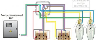
Connection diagram for the pass-through switch wires in the distribution box
Circuit without grounding conductor. Now the most important thing is to correctly assemble the circuit in the junction box. Four 3-core cables should go into it:
- power cable from lighting circuit breaker
- cable to switch No. 1
- cable to switch No. 2
- cable for lamp or chandelier
When connecting wires, it is most convenient to orient them by color. If you use a three-core VVG cable, then it has two most common color markings:
- white (gray) – phase
- blue – zero
- yellow green – earth
or second option:
- White gray)
- brown
- black
To choose a more correct phasing in the second case, follow the tips from the article “Color marking of wires. GOSTs and rules.”
- The assembly begins with neutral conductors. Connect the neutral conductor from the cable of the input machine and the neutral going to the lamp at one point using the terminals of the car.
- Next, you need to connect all the grounding conductors, if you have a grounding conductor. Similar to the neutral wires, you combine the “ground” from the input cable with the “ground” of the outgoing cable for lighting. This wire is connected to the lamp body.
- All that remains is to connect the phase conductors correctly and without errors. The phase from the input cable must be connected to the phase of the outgoing wire to the common terminal of the pass-through switch No. 1.
And connect the common wire from pass-through switch No. 2 with a separate wago clamp to the phase conductor of the lighting cable.
Having completed all these connections, all that remains is to connect the secondary (outgoing) conductors from switch No. 1 and No. 2 to each other. And it doesn’t matter at all how you connect them.
You can even mix up the colors. But it’s better to stick to the colors so as not to get confused in the future. At this point, you can consider the circuit fully assembled, apply voltage and check the lighting.
Electrical switching
Before starting work, do not forget about your safety, turn off the power supply circuit breaker, check that there is no voltage, and only then proceed with installation and switching operations with electrical wiring.
Five wires should fit into the junction box:
- 2-wire – zero and phase from the supply network;
- 2-core – zero and phase from the lighting device;
- 3-wire – from one pass-through switch;
- 3-wire – from the second pass-through switch;
- 4-wire - from the cross switch.
If your lamp must be structurally grounded, then you will need a wire with three cores both to connect the lighting device and for the supply network (phase, ground and neutral).
Each connection must be made in a distribution box; it is convenient to connect several sections of electrical wiring in one place. The box itself acts as an intermediate link between the power supply and the pass-through switches.
Now let's connect, there is nothing complicated, the main thing is to be careful:
- First, the neutral wire from the supply network is connected to the neutral wire going to the lamp.
- Connect the phase wire from the supply network to the core going to the common incoming contact of the first pass-through switch.
- Now a pair of wires from the output contacts of the first pass-through switch is connected to any one pair of wires of the crossover device.
- Absolutely similar switching is carried out with the second pass-through switch. Its pair of wires from the outgoing contacts is connected to the remaining pair of wires of the crossover device.
- It remains to connect the lamp phase with the core of the common incoming contact on the second pass-through switch.
Make the appropriate connections of the wires on the switch contacts and in the lighting fixture socket (phase and zero).
We advise you to first test the operation of the assembled circuit, and then only isolate the places of twisting in order to see for sure that everything was done correctly. Turn on the machine from the power source and test the operation of the switches. Any of the three switching devices turns the light on and off. Is everything working correctly? Then complete the work. Turn off the voltage again, insulate the twisted areas with electrical tape, and secure the protective covers and keys on the switches.
The connection diagram for a two-key pass-through switch is carried out in a similar way, only in this situation you will need to install two crossover devices.
You can connect both a fourth and a fifth switch to the lamp control circuit, then you can control an even larger space, for example, the entrance lighting of a multi-story building. Of course, in such cases the scheme will be more complicated. But if you understand the principle itself in the considered control scheme from three places, you will also be able to cope with a large number of points.
Design and features of pass-through switches
The external pass-through device does not differ from the standard one. The difference can only be noticed when examining the product from below - manufacturers apply triangles on the body, directed horizontally downwards. The second difference is 3 terminals with copper contacts. One is located on top, and two are located below. Also, the pass-through device is switched through a three-core VVG-ng or NYM cable with a cross-section of 1.5 mm².
Depending on the number of buttons, there are two-key, one-key and three-key modifications.
The difference between a pass-through and a regular switch.
In comparison with classic two-pole models, you need to connect the adapter according to the following principle:
- serial connection of switches;
- the phase does not open, but switches to the second line;
- There are more output contacts than input contacts.
The paired poles of the switches are located opposite each other.
Nuances of choice
Before purchasing a pass-through switch, you need to consider:
- Mounting method depends on the type of wiring. Overlays are installed on the surface using self-tapping dowels. Built-in - in socket boxes on spacer legs.
- Degree of protection - models with IP03 are suitable for a bedroom or corridor, for a bathroom - with IP04-IP05, for the street - with IP55.
- Type of contact terminals. Screws with pressure plates are reliable. Screwless spring ones are easier to install.
- Terminal markings - N (zero), L (phase) and ground (ground) are used. The letters I and O indicate the position of the buttons when turned on and off.
According to the type of control, the adapters can be keyboard, touch, or with remote control.
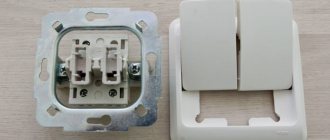
Connecting a pass-through switch
First of all, you need to correctly connect the switch itself in the socket box. Remove the key and the overhead frames.
When disassembled, you can easily see the three contact terminals.
The most important thing is to find the common one. On high-quality products, a diagram should be drawn on the reverse side. If you understand them, you can easily navigate through it.
If you have a budget model, or any electrical circuits are a bit of a mystery to you, then an ordinary Chinese tester in circuit continuity mode, or an indicator screwdriver with a battery, will come to the rescue.
Using the tester's probes, alternately touch all the contacts and look for the one on which the tester will “squeak” or show “0” at any position of the ON or OFF key. It's even easier to do this with an indicator screwdriver.
After you have found the common terminal, you need to connect the phase from the power cable to it. Connect the remaining two wires to the remaining terminals.
Moreover, which one goes where does not make a significant difference. The switch is assembled and secured in the socket box.
Do the same operation with the second switch:
- look for the common terminal
- connect the phase conductor to it, which will go to the light bulb
- connect two other wires to the remaining ones
Connecting a pass-through switch diagram from three places
Connection diagram for a pass-through switch with 3 places: photo and video instructions
For a certain configuration of premises (the central entrance is located in the middle of the corridor, it has a branch) or the organization of lighting for the entrance of a multi-storey building, a scheme for controlling electrical energy consumers from three or more places is used.
It is built on the basis of two pass-through and several crossover switches.
Peculiarities
The principle of connecting pass-through switches differs from that used when installing classic devices with two poles.
- Switches are connected in series to each other.
- It is not an opening, but a phase switching to another line.
- The number of output contacts of a pass-through switch is twice as large as the input ones.
The general mnemonic rule when constructing such a circuit is formulated as follows: paired poles of switches “look” at each other .
Video instructions on how to draw up a diagram for connecting a two-key pass-through switch from three places:
Installation of the third control point
Since the pass-through devices are connected in series, the third and subsequent control points are located in the gap between them. If you use the same device as a third switch, then the fourth pole of the line will be “suspended”, and one of the lines will be inactive .
Of course, you can short both lines to the output terminal. But in this case you will turn it into a regular household switch. This scheme will work, but only in one direction.
The connection diagram for a pass-through switch with 3 places is shown in the photo:
For example, you entered the corridor, turned on the light and reached the place where such a switch was installed. Turn off the light. Now you can turn it on either from the same place where you entered, or where you turned it off. It is not comfortable.
Therefore, another type of switch is used - crossover . It has four terminals. If you take it apart, inside you will see two combined moving contacts.
With one movement of the key both move. The fourth output pole also has two contact points. After pressing the key, the phase lines conditionally cross (without electrical contact) . but the principle of connecting the end devices remains the same.
The back side of the cross-switch housing
is marked with poles and the conditional direction of phase movement from the distribution box to the consumer.
Both lines on one side of the right or left end must be connected to the terminals, which are marked with arrows pointing in the same direction. The direction is not of fundamental importance . but ideally it is worth observing it too. This will allow you to avoid confusion in the future about where you started and where you ended.
In practice, you may encounter the fact that the electrical goods store does not have the required element (crossover switch). This is not a reason to abandon your plans. The process of converting one into another is simple and accessible to any master . familiar with pliers and a screwdriver.
Converting to cross
To convert a pass into a cross, use the one that has two keys. It has two input pins and four output pins . The design change is carried out in two stages:
- The output poles are cross-connected.
- Changes are being made to the mechanical part.
The electrical circuit of the device is changed using conductive jumpers - pieces of wire of the same diameter . They need to close the output contacts according to the following scheme: extreme to extreme, central to central .
There are two types of pass-through switch designs . differing in the location of the input terminals - they can be arranged either on one side of the housing or towards each other. In the latter case, the jumpers will visually intersect.
In order for the moving contacts to work simultaneously, it is enough to combine the keys themselves in some way.
It is better not to make changes to the mechanical part of the device.
The converted pass-through switch can be used in a model for controlling one lamp or several . connected in parallel. If there are several consumers, then the number of crossover switches should be the same. This significantly complicates installation work.
But from a fire safety point of view, several separately connected devices are better . than one large terminal strip. Therefore, the possible costs are justified.
Find out how to correctly connect a pass-through switch from two places using a diagram from this article.
Some subtleties
If you need to create several intermediate control points for lighting devices, for example, for the staircases of a five-story building, then they are all switched on in series. The same phase must pass through them .
There is an opinion that to install intermediate switching points for lighting fixtures, you should use exclusively a four-core cable. This simplifies installation work.
There is some truth in this, but there is a real threat of including a wire of the wrong size into the line. This is because cables with so many conductors are designed for three-phase current, the fourth core in them is one third smaller in diameter, it is connected to the ground loop. Phase current cannot be passed through it.
All work on connecting an additional on-off point is carried out with the voltage removed and other electrical safety measures observed.
Connection diagram for pass-through and cross switches from 3 places:
Connection diagram for a pass-through switch with 3 places
- Using three-switch circuits
- Elements and components of the connection diagram
- How to connect a pass-through switch from 3 places
- input connected to output 1;
- input is connected to output 2.
The feasibility of using walk-through switches is determined by the individual layout of the room with lamps that require adjustment from different points. Thus, additional convenience and comfort are provided. In such cases, a circuit for connecting a pass-through switch from three places is quite often used. If necessary, it is possible to use more points.
Using three-switch circuits
Using a light control system with three switches makes it possible to turn the lighting on and off from any convenient location. Walk-through switches have proven themselves well on flights of stairs, in large rooms, entrances, as well as in the yard or on a personal plot.
In long corridors, several switches are installed, at the beginning, in the middle or at the end. The same scheme is used when there are several entrances to different rooms. That is, at the beginning of the corridor the light can be turned on, and in the middle or at the end it can be turned off. In order for the lighting device to be turned on and off from three different points in the room, it is necessary to use a connection diagram with three pass-through switches.
Elements and components of the connection diagram
This circuit includes a junction box, lighting fixtures, switches and wires. Not only conventional incandescent lamps are used as lighting sources, but also various types of LED and energy-saving lamps. The switches used in the circuit are divided into pass-through and cross-type. In turn, pass-through switches can be changeover, redundant or ladder switches. Their installation takes much longer compared to conventional switches.
The classic scheme for connecting a pass-through switch from three places requires the use of two pass-through switches and one cross switch. The appearance of the duplicating devices is almost the same as that of a single-key device. In any position of the keys of such a switch, the connection of the electrical circuit is not interrupted, only the contacts are switched. The switching mechanism in pass-through switches is located in the center of the contacts.
Devices can be one- or two-key. In the second case, two devices are combined into one with six contacts. Circuits often use single-key light switches that do not differ from each other. Each of them is equipped with three contacts. The first device has a phase wire connected to one contact, and intermediate wires to the other two. The third switch, on the contrary, has an intermediate wire connected to one contact, and output phase lines to the other two.
The switch installed in the middle performs the function of a cross switch. It has four contacts, from which two wires go to each changeover switch No. 1 and No. 3. If the intermediate electrical wire is shorted on any of the changeover devices, the light will turn on. When the state of the key changes, the circuit breaks and the light goes out. If there is a need to increase the number of light control points, it is enough to add cross switches in the required number to the existing circuit.
To correctly install the control system, certain recommendations must be followed. If the room already has an electrical network, then separate open or closed networks must be connected to the backup switches. In the second case, you need to make grooves in the walls. You may need special tools and plaster to secure the corrugated pipe. New lines are laid using a three- or four-core cable.
How to connect a pass-through switch from 3 places
Color coding of resistors online.
Home » Electrical » How to connect a pass-through switch (light control from two or more points)
How to connect a pass-through switch (light control from two or more points)
Current electricity prices make you think about saving where you never even thought about it before. For example, lighting on the stairs. It doesn’t matter if it’s in a private or multi-storey building, you still need to pay. Previously, they simply left the light on. Today you think about turning it off, but running up and down is also not fun. It turns out there is a solution. To prevent the lights from being on constantly, there are schemes for controlling the lamps from several places. That is, one or more lamps can be turned on and off from several points. Special switches are needed for this. They are called walk-throughs. Sometimes the names “duplicate” or “change-over” are found. All this is one type of electrical equipment. They differ from ordinary ones in a large number of contacts. Accordingly, the connection diagram for the pass-through switch is more complicated. However, you can figure it out.
What does a pass-through switch look like and work?
If we talk about the front side, the only difference is: a barely noticeable arrow on the up and down key.
What does a single-key pass-through switch look like? You see there are double arrows
If we talk about the electrical circuit, everything is also simple: in ordinary switches there are only two contacts, in pass-through switches (also called changeover contacts) there are three contacts, two of which are common. There are always two or more such devices in the circuit, and they are switched using these common wires.
The difference is in the number of contacts
The operating principle is simple. By changing the position of the key, the input is connected to one of the outputs. That is, these devices have only two working positions:
There are no other intermediate provisions. Thanks to this, everything works. Because the contact switches from one position to another, electricians believe it is more correct to call them “switches.” So a pass-through switch is also this device.
In order not to rely on the presence or absence of arrows on the keys, you need to inspect the contact part. Branded products should have a diagram on them that allows you to understand what type of equipment you have in your hands. It is definitely found on products from Lezard, Legrand, and Viko. They are often absent on Chinese copies.
This is what the changeover switch looks like from the rear
If there is no such diagram, look at the terminals (copper contacts in the holes): there should be three of them. But not always on inexpensive copies the terminal that stands alone is the input. They are often confused. To find where the common contact is located, you need to ring the contacts with each other at different key positions. This must be done, otherwise nothing will work, and the device itself may burn out.
You will need a tester or multimeter. If you have a multimeter, set it to sound mode - it beeps when there is contact. If you have a pointer tester, ring for a short circuit. Place the probe on one of the contacts, find which of the two it rings with (the device beeps or the arrow shows a short circuit - it deviates to the right all the way). Without changing the position of the probes, change the position of the key. If the short circuit is missing, one of these two is common. Now all that remains is to check which one. Without switching the key, move one of the probes to another contact. If there is a short circuit, then the contact from which the probe was not moved is the common one (this is the input).
It may become clearer if you watch a video on how to find the input (common contact) for a pass-through switch.
Connection diagram for a pass-through switch from two places
This scheme is convenient in a two-story house on the stairs, in a passage room, in a long corridor. You can also use it in the bedroom - turn off the overhead light at the entrance and near the bed (how many times did you have to get up to turn it on/off?).
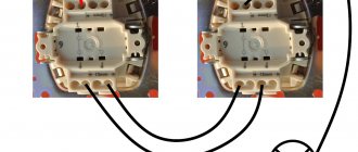
Electrical diagram for switching on a pass-through switch from 2 places
Zero and ground (if any) are connected directly to the lamp. The phase is supplied to the output of the first switch, the input of the second is connected to the free wire of the lamp, the outputs of the two devices are connected to each other.
Looking at this diagram, it is easy to understand how the pass-through switch works. In the position shown in the figure, the lamp is on. By pressing the key of any of the devices, we break the chain. In the same way, when in the off position, by moving any of them to another position, we will close the circuit through one of the jumpers and the lamp will light up.
To make it clearer what to connect to what, and how to lay the wires, here are a few images.
Connecting wires on a pass-through switch
If we talk about the room, then you need to lay the wires approximately as in the photo below. According to modern rules, all of them should be located at a distance of 15 cm from the ceiling. They can be placed in mounting boxes or trays; the ends of the wires are inserted into mounting boxes. This is convenient: if necessary, you can replace a broken wire. Also, according to the latest standards, all connections occur only in installation boxes and using contactors. If you make twists, it is better to solder them and wrap them well with electrical tape on top.
The return wire of the lamp is connected to the output of the second switch. White indicates the wires connecting the outputs of both devices.
How to route wires around the room
How to connect everything in the terminal box is described in the video.
3 point circuit
To be able to turn the light on/off from three places, you need to buy a cross (cross) switch for two switches. It differs from those described earlier by the presence of two inputs and two outputs. It switches a couple of contacts at once. See the figure for how everything should be organized. If you understand the above, this one is easy to understand.
Electrical circuit for controlling a lamp from three points
How to assemble such a circuit? Here's the procedure:
The same diagram, but from a different perspective - where to connect the wires on the housings.
Where to connect the wires
And this is approximately how to distribute it around the room.
Wiring when controlling the lamp from three places
If you need a circuit with four, five or more points, then it differs only in the number of cross switches (for four inputs/outputs). There are always two switches (with three inputs/outputs) in any circuit - at the very beginning and at the very end of the circuit. All other elements are cross devices.
Connection diagram for pass-through switches for 5 points
Remove one “crossbar” and you get a four-point control scheme. Add more and there will be a scheme for 6 control places.
To finally get it all in your head, watch this video.
Two-key pass-through switch: connection diagram
To control the lighting of two lamps (or groups of lamps) from one switch from several places, there are two-key pass-through switches. They have six contacts. If necessary, find the common wires using the same principle as in a conventional device of this type, only you will have to connect a larger number of wires.
The connection diagram for a 2-key pass-through switch differs only in that there will be more wires: the phase must be supplied to both inputs of the first switch, just as from the two inputs of the second it must go to two lamps (or two groups of lamps, if we are talking about a multi-arm chandelier ).
The principle of connecting two-key pass-through switches
If you need to organize control of two light sources from three or more points, you will have to install two cross switches at each point: there are simply no two-key switches. In this case, one pair of contacts is placed on one crossbar, the second on the other. And then, if necessary, they are connected to each other. The outputs of both crossbars are connected to the last two-key transition switch in the chain.
How to organize control of two lamps from four places
If you think about it, everything is not so complicated, and the connection diagram for a pass-through switch from 2 points is generally simple. Just a lot of wires...
- Connection diagram for a pass-through switch How many times have you had to feel your way out of a room along a dark corridor to turn on the light...
- Connection diagram for a two-button switch High-quality home repairs involve replacing electrical wires, sockets and switches. Many questions arise here...
- Wiring diagram for a single-key switch School physics lessons, teachers and grades are a thing of the past, and electrical tasks are for men...
- Diagram of a two-key pass-through switch from two places Home » Electrical » How to connect a pass-through switch (light control from two or more points)…
Changeover switches - lighting control circuit from 3 places
But what if you want to control one lighting from three or more points. That is, there will be 3, 4, etc. switches in the circuit. It would seem that you need to take another pass-through switch and that’s it.
However, a switch with three terminals will no longer work here. Since there will be four connected wires in the junction box.
Here a changeover switch, or as it is also called a cross, cross, or intermediate switch, will come to your aid. Its key difference is that it has four exits - two from below and two from above.
And it is installed precisely in the gap between two passageways. Find in the junction box two secondary (not main) wires from the first and second pass-through switch.
Switching diagram
What's special?
Externally, a pass-through switching device looks like an ordinary one, but that is until you begin to carefully study its structure.
A conventional device has two contacts - input and output; when you press a key, they close or open with each other, thus creating an electrical circuit or breaking it.
The pass-through switch has three contacts - one common input and two output. Inside the contact part there is a changeover element, which is never in an intermediate position in the middle. When you press a key, it switches to one or the second circuit, so it connects the common input contact to one or the other output.
The triple lighting control option involves the use of a cross switch. Its design feature is that there are four contact points (two input and two output).
The crossover switch is always connected in the middle between the pass-throughs. One pair of its contacts is connected to the output contacts of the first pass-through device, the second pair, respectively, to the output contacts of another pass-through switch.
Keep in mind that when connecting switches from 3 different places to one lighting group, all three switching devices duplicate each other's actions. In this regard, their keys will not have clearly marked “on” or “off” positions; each time they can be in different positions.
The operating principle of pass-through and crossover switches is shown in detail and clearly in the video from Alexey Zemskov:
What will you need?
To carry out electrical installation work, purchase the following materials:
- junction box;
- lighting fixture;
- pass-through switches – 2 pcs.;
- cross switch;
- socket boxes - 3 pcs.;
- 2, 3 and 4-wire wire.
Also, when working, you should always have the following tools at hand:
- side cutters;
- Screwdriver Set;
- a tool for removing the insulating layer from wire cores;
- multimeter;
- a tool for making grooves and holes in walls.
Application of the scheme
In long corridors, pass-through switches are often used. Pass-through models are designed for the convenience of supplying or removing voltage from lighting fixtures from different ends of the room. Most often this scheme is used:
- In a long corridor with exits from different rooms. One switch is placed at the exit, a second one in the middle, and a third one at the end.
- In the courtyards of country and private houses, dachas. Switching devices are installed at the exit from the house and outbuildings.
- In three-story apartment buildings. A device is placed on the ground floor to turn it on. You can turn off the lighting on the second and third floors.
- In a children's room with several beds. The solution provides for one device at the entrance and two next to the sleeping areas.
- Flights of stairs and landings of cottages outside the city. One device is mounted at the beginning of the stairs, switching off is carried out from the second floor or near the attic.
By using a pass-through switch, energy savings are ensured.
Working principle of the cross disconnector
The pass-through device for turning the light on and off inside has four terminals - it looks the same as regular switches. Such an internal device is necessary for the cross-shaped connection of the two lines that the switch will regulate. The disconnector can at one moment disconnect the two remaining switches, after which it connects them together. The result is turning the light on and off.
To create a circuit, two or more pass-through switches are used. The circuit can include any number of pass-through devices, but increasing their number will seriously complicate the work - you need to clearly know the order of the cables and connections in the box.
Disadvantages of pass-through switches
One of the disadvantages of walk-through switches is the need to drill walls under them. Organizing a power line with a pass-through switch has several disadvantages:
- time and effort spent on wall slitting for hidden wiring;
- the need to connect the remote control via a regular key for models with motion sensors;
- unprofitability for an apartment due to cable grooves and installation of a DIN rail;
- difficulties with identifying terminals;
- lack of clarity of the “ON” and “OFF” positions.
Experts note that the devices are more suitable for country cottages, dachas, and the private sector than for an apartment.
A pass-through switch is convenient to use in rooms with several groups of lighting fixtures. The device provides comfortable light control and safe movement of people. Currently, the pass-through light switch circuit, controlled from three places, is not tied to the layout of a residential property.
Three control point solution
The organization of pass-through switching systems is largely determined by the area of the premises (length) and the number of passages (doors). Therefore, the use of circuits with pass-through switches from three or more control positions is not excluded.
The construction of such circuits is usually carried out using a so-called cross switch.
This is the same switch, but in terms of circuit design it is made with five contact terminals, two of which are short-circuited with a jumper. The switching group of such a switch contains four contact pads.
A widely used circuit design for residential buildings: N, L – household network; RK – distribution box; L1 – light group; PV1, PV2 – pass-through switches; PRK – cross commutator (+)
The line cross-switching device is an additional element of the circuit, which also involves the installation of two pass-through switches.
Simple single-key instruments are used.
The operating principle of the three-seater scheme is as follows:
- A phase is connected to the “common” terminal PV1.
- The 1st and 2nd contacts of the crossover switch are connected from the changeover contact terminals.
- From the 3rd and 4th terminals of the crossover switch, connection to the 1st and 2nd terminals of the PV2 changeover contacts.
- The common terminal “common” PV2 is connected to one terminal of the light group.
- The second terminal of the light group is connected to the electrical zero.
Such solutions involving simple single-key devices are recommended for use in rooms where the number of inputs/outputs is equal to the number of control places.
Implementation of the circuit design according to Fig. 6 in a “natural” form. This is roughly what a completed installation looks like indoors, where a control system from three places is needed
For example, creating a similar circuit for the conditions of passing a long corridor, with 1 entrance and 1 exit, with switching in the central zone, is clearly impractical. Obviously, it makes no sense to turn off the lights when a person has only passed the first half of the corridor. Meanwhile, you can find similar recommendations from “professional” electricians on the Internet.
Schemes with control from more than three places
The number of control places is, in principle, unlimited. Another question is how complex such decisions are. The more devices are involved in the implementation of the control system, the more complex the construction scheme becomes.
The number of switched lines and contact terminals is increasing. Accordingly, costs for components and installation increase. However, projects with 4-5 control points are used quite actively. For example, this project:
Circuit design for projects that require an increase in the number of control locations of more than three. In this case, the option is for four control points (+)
It uses a pair of single-key simple pass-through switches and a pair of switches with a reversible switching function. The diagram shows only one light group. Meanwhile, it is possible to connect additional light groups.
Additional light groups
Additional light sources (light groups) can be connected via free terminals and act as light sources for intermediate transition zones. That is, in the same long corridors it becomes possible to use the circuit for a larger number of control positions.
Five-point control circuit for the light switching system: L1 – light group; N, L – network; On 1, On 2 – pass-through switches; On 3, On 4, On 5 – reversible switches (+)
In this case, light groups should be divided into action zones - entrance, intermediate, exit. With this solution, it is already possible to walk through a long corridor halfway, turn off the lights on the completed half and turn on the lights on the remaining half.
Multi-element schemes, of course, are of little use for the private residential sector, since projects of this kind rarely have long corridors or large rooms with several doors. But for the commercial sphere or production environment, solutions of this kind are in demand.
Connection errors
Many people make a mistake at the stage of searching and connecting the common terminal in the pass-through switch. Without checking the circuit, they naively believe that the common terminal is the one with only one contact.
They assemble a circuit in this way, and then for some reason the switches do not work correctly (they depend on each other).
Remember that on different switches the common contact can be anywhere!
And it is best to call it, what is called “live”, with a tester or an indicator screwdriver.
Most often, this problem is encountered when installing or replacing pass-through switches from different companies. If everything worked before, but after replacing one circuit the circuit stopped working, it means the wires were mixed up. But there may also be an option that the new switch is not pass-through at all. Also remember that the lighting inside the product cannot in any way affect the switching principle itself.
Another common mistake is incorrectly connecting crossovers. When both wires are placed from pass-through No. 1 to the upper contacts, and from No. 2 to the lower ones. Meanwhile, the cross switch has a completely different circuit and switching mechanism. And you need to connect the wires crosswise.
Connection diagram
Connecting cores to the switch terminals
Before connecting the three-key switch, you will need to disassemble it into its component parts. To do this, first remove all three keys using a flat-head screwdriver, and then remove the decorative frame. After this, access to the terminals to which you need to connect the phase wires opens.
Before starting work, it is important to decide on the circuit by which the purchased device is supposed to be connected. When choosing it, the following options are possible:
- The user expects to turn on three light bulbs in a chandelier in stages. It is planned to use a distribution box for switching.
- To obtain the same effect, direct connection of conductors is assumed. The liner goes directly to the lamp contacts.
The connection diagram for each of these cases has its own characteristics.
Connecting three light bulbs through a junction box
Connection via junction box
Three phase wires taken from the upper terminals of the switch are laid in the cable channel in the direction of the junction box. It disconnects them and then creates a branch towards the chandelier. Each of the power bars is switched in such a way that voltage is supplied through it to a separate light bulb. In this case, it will be possible to turn on the lamps in stages - one after another until maximum illumination is achieved.
This approach is convenient because if it is necessary to adjust the circuit, it is enough to change the connection in the box without touching the chandelier itself.
Direct connection
Connection diagram for three chandeliers from a triple switch
The user saves on consumables and gains in reliability. The basic rule of electrical engineering is: the fewer contacts, the more reliable the circuit.
Three bars extending from the switch terminals are laid in the cable channel directly to the chandelier. Inside the illuminator, they are switched in accordance with the color marking of the conductors. If it is not available, you will have to use a multimeter turned on in the “Dial” mode. With its help, the cores are determined that are connected to the metal base of all three holders: this will be the zero contact. The remaining three conductors are connected to the contact patches of the lamp holders: these are phase connections. After marking, each of the wires is connected via miniature adapters to the corresponding busbars removed from the switch. The order in which they are switched does not matter, since the light bulbs usually turn on in random order.
Example of lighting operation
- When you turn on key No. 1, the lamp lights up, electricity flows through the phase wire and is indicated by the letter L, and the flow of current is shown by the red line.
- Press the key back and the light goes out.
- We switch the adapter disconnector, the lamp lights up.
- Press the key again and the lamp turns off.
- When device No. 3 is turned on, the lamp lights up.
- Pressing again turns off the lamp.
Recommendation: if it is necessary to increase the number of control points for the luminaire, add the desired number of cross switches between the staircase switches.
Installation work
Installation of walk-through switches
Installation of the lighting system is carried out according to the following algorithm:
- Search for the common terminal point on the adapter.
- Connection to the first switch next to the phase distribution box.
- Fastening the phase to the common terminal with an orange or red cable.
- Connection of the 2 remaining conductors at the output internal terminals of the pass-through device.
- Throw wires and fasteners onto the second switch according to the color marker.
- Connecting the orange/red conductor from switch No. 2 to the light bulb phase inside the box.
- Connection inside the distribution box according to the color designation of 2 free wires to the core of switch No. 1.
At the end, the neutral and ground are connected inside the box to similar wires connected to the lighting device.
Two-key
Contacts of a two-key connector
To control the operation of light sources from two points, a two-key connector with 6 contacts is used. Installation of the pass-through switch occurs as follows:
- Detection of common contacts.
- Supply of phase wire to the input of switches No. 1 and No. 2.
- Connecting the remaining inputs with a switch to the ends of lamps No. 1 and No. 2.
- Connecting the free ends of the lamps to the neutral cable.
- Connecting 2 outputs of switch No. 1 to the outputs of switch No. 2.
- Similar fastening of the remaining outputs.
When using two two-key switches, the length of the wires increases.
Three-key
A three-key device is similar in connection type to a two-key device. The difference is that you will need to add a fourth wire. One cable carries the phase to the switch, three cables send it to the load. Installation is carried out as follows:
- Find the terminals for connecting the phase conductors on the side parts of the contact block.
- Connect phase cable No. 1 from the side of one terminal.
- Connect the remaining three phase wires to three terminals.
- Phase No. 1 is inserted into the distribution box and connected to the cable wire leading to the switch.
- At the input, the phase is connected to the lower input contact.
- From the three output contacts of the switch at the top, three phase cables are taken into the distribution box and connected to the wires leading to the ceiling.
- On the ceiling, the phase wires are thrown onto the terminals of the lamps.
The neutral must be inserted into the distribution box and connected to the wire directed to the ceiling. There, zero must be connected to the blue point of the lamp terminals to form a common terminal.
Necessary equipment and materials
- Switches
- Mounting box
- Electrical insulating tape
- Terminals
- Phillips and regular screwdrivers
- Installation knife
- Side cutters
- Pliers
- Wrenches
- Electric cable
If the room has already been wired and you need to install redundant switches, then you need to make grooves or open installation of cables. In order to make grooves you will need a hammer drill and a wall chaser. You also need alabaster. He will secure the corrugated pipe. In case of open installation, a distribution box is required; it is attached to the wall using a corrugated pipe.
Three-key switch: convenience and energy saving
A three-key switch allows you to save up to a third of electricity. The device is a fairly simple device, externally differing from one- and two-key models only in the number of keys. Unlike simple switches, the three-key model has three groups of contacts for phase and zero. The main thing is not to confuse them when connecting.
Preparatory work includes:
- mandatory network de-energization;
- wire distribution (zero, phase);
- phase search (using an indicator screwdriver).
If the old switch has failed or repairs have been made to the room, it becomes necessary to connect a new switch. Before you begin installation, you need to buy the switch itself.
Selecting and purchasing a three-key switch
It is recommended to purchase equipment only from well-known companies. This guarantees long-term operation of the product and its trouble-free service.
When purchasing, it is recommended to pay attention to the following details:
the keys should turn on with a characteristic click and not stick; the surface of the switch must be smooth and even; on the back there should be a diagram for connecting to the electrical network; It is important to check the degree of protection and make sure that the product can be connected in a specific room.
The degree of protection is designated as IP and consists of two numbers (from zero to six). The first number is responsible for dust protection, and the second for water protection. The higher the number, the more reliable the protection. For living rooms, a switch with an IP rating of 20 is suitable. If the room has high humidity (bathroom, bathhouse) or an increased amount of dust (attic), then the IP rating should be at least 44. Electrical installation work outdoors requires the installation of a switch with IP 65.
Connection diagram
Domestic and foreign companies are engaged in the production of electrical equipment, but the connection diagram for a three-key switch is always the same.
The general diagram will help you correctly connect any three-key switch
A set of necessary tools
To connect you will need tools, most of which are found in every house or apartment:
- nippers and pliers;
- Phillips and flat-head screwdrivers (depending on the features of the product);
- indicator screwdriver;
- insulating tape;
- screwdriver;
- knife or stripper (a tool for convenient removal of insulation).
Step-by-step installation instructions
- Disconnect power to the room.
- Determine where the wires are so as not to damage them.
- Designate the future location of the junction box.
- Install the mounting box.
- Laying electrical cables. It is better to take a 3 or 4 core cable. For changeover devices, a three-wire cable is required. Using one core, a phase supply or a lamp will be connected. Two cores are connected to intermediate wires. For a crossover device, you need a four-core cable - two wires for each switch. Two will lead to the first, and the remaining two will lead to the second.
The ends of all cables are led into the installation box and connected with terminals. And the zero goes to the lamp. To equip a pass-through switch with control from 3 places, you must have skills and an accurate connection diagram. Its presence makes it possible to install a correct and high-quality lighting system. And on its basis you can easily create more complex illumination schemes.
Materials and tools for arranging a control circuit
First of all, you need to decide on the topology of laying cables and lighting wires. Since all switches are connected in series, it makes sense to route the conductors in a loop without using junction boxes. This option is suitable for both hidden and open wiring.
Laying cables for daisy chain installation.
You will need a cable with a cross section of 1.5 sq. mm:
- of two conductors from the switchboard to the first pass-through switch;
- three-core from the first through to the crossover;
- three-wire from crossover to second through;
- two wires from the second cross to the lamp (group of lamps).
In this option, the neutral wire goes along with the phase wire along the entire length of the wiring. The disadvantage of this solution is the need to connect the neutral conductor at several points, which is undesirable for safety reasons - the likelihood of a zero break due to many terminal strips or twists increases. You can lay this line with a separate wire directly from the switchboard to the lamp, then the number of wires in each section will decrease by one.
If you cannot do without installing a distribution box or the control circuit is built into an existing lighting system, the installation can be done differently.
Installation using a distribution box.
Galvanically, this circuit does not differ from the previous one and works similarly. The first and last switches are connected to the phase wire break in the box.
| Cable | Core material | Number of cores | Additional properties |
| VVG 1x1.5 | copper | 1 | |
| VVGng 2 x 1.5 | copper | 2 | Incombustible |
| VVG 2 x 1.5 | copper | 2 | |
| NYY-J 3x1.5 | copper | 3 | |
| VVG 3x1.5 | copper | 3 |
The names of some cables suitable for use in arranging the circuit are given in the table.
Lighting control
Depending on the type of lighting system you prefer, wiring can be done in different ways. Despite the fact that the design features of all standard pass-through switches are the same, there are several differences in the connection diagram of the system with control of two and three places.
Before you begin self-installation, you must turn off the electrical power supply, which is dictated by safety regulations.
Control from 2 places
Controlling the light from two places is often a very convenient solution.
This method of organizing the control of lighting devices is most often used when it is necessary to control the process of turning on/off light sources not only from the room itself, but also from adjacent rooms.
In this case, as a rule, preference is given to installing switching devices to control a couple of consumer groups:
- thorough removal of decorative coatings in the wiring area;
- marking the proposed wiring line;
- scoring according to the markings made, starting from the shield, taking into account the free distance to the upper edge of the cable channel with dimensions of ½ the diameter of the laid wires;
- checking the horizontality of the completed lines;
- laying electrical cable. It is quite possible to fix laid electrical wires with special fasteners without damaging the protective sheath;
- installation of switches and distribution boxes;
- connecting laid electrical conductors to terminals in accordance with color markings.
Lighting control scheme from two places
The assembled wiring is inserted into special mounting boxes, after which they are securely and durablely fixed with built-in retractable mechanisms with pointed elements.
Only after testing has been carried out and the operability of the entire lighting system has been confirmed, cable channels are cemented, wall surfaces are finished and frames are installed.
Control from 3 seats
Independent installation of control from three places is a more complex system that can cause some difficulties for untrained installers. The most common electrical circuit is based on one crossover and a pair of pass-through switches.
Work technology:
- preliminary preparation of grooves for laying electrical cables using a hammer drill;
- laying electrical cables with an optimal cross-section of 2.5 mm2 or more;
- connecting wires to the electrical panel;
- choose the optimal height for mounting the switch that is comfortable for operating the switching device;
- Drill a hole in accordance with a pre-made mark, which is one and a half times larger in width and depth than the diameter of the device being installed;
- electrical wiring is connected to the switching device from below, so the groove must be made 50-100 cm lower than the installation point of the switch;
- laying electrical wires in prepared grooves with fixing the wiring elements using small special nails;
- insertion of electrical wires fixed in the channels into the installation box;
- cutting the wires inside the wiring box to a length of 10-11 cm using side cutters;
- removing approximately 10-15 cm of the insulating layer from the wires;
- installation of a pass-through switching device (switch) with connection to the terminals, according to their markings;
- installation of a cross-switching device with four electrical cables of the corresponding color marking;
- connecting the first pair of electrical cables from the pass-through switch to the upper terminals, and the remaining two wires are fixed to the lower terminals;
- connecting the last switching device using wires coming from the communication crossover device.
Connection from three places
At the final stage, it is necessary to carefully insert the device mechanisms inside all the completed mounting boxes, bending the cables to their base. Then the devices are fixed using special fasteners inside the mounting box or “claws” on the clamps
Next, the frame is applied, and then the keys of the switching device are mounted.
Wiring when controlling the lamp from three places
The completion of self-installation of a switch to control the lighting system from three different points is the connection of lighting fixtures with electrical cables coming from the junction box, checking the functionality of the circuit and subsequent decorative finishing.
Touch switch models
In addition to keyboard and lever modifications, there are touch-sensitive models on the market. In essence, the functions of the devices are the same, but the principle of operation, as well as the design, are somewhat different.
The modern modification is a touch model, which has a more convenient operating principle. In addition, this type of household communicators has an increased service life due to the absence of mechanics in the design
There are two types of touch switches:
- Direct sensors.
- Touch sensors with dimmers.
The first ones work on direct, clear contact through a brief touch of the fingertip to the glass panel of the device. That is, in this option only the on/off function works. The second design option (dimmer) provides switching on and off with smooth control of the brightness of the lamps.
To work with these devices, the same finger touch is required, followed by holding the fingertip on the glass until the required brightness of the lamp is achieved.
Rear view of the touch device, where the connection terminals are located: COM – synchronizing connector for working in pairs with other devices; L – contact for the network phase; L1 – first output channel; L2 – second output channel
The circuitry of sensor devices differs from devices of other designs in that it contains one common (phase) terminal (L), two changeover terminals (L1, L2) and one “COM” terminal.
The "COM" contact is used for communication between switches when building complex circuits. For example, with control of several lighting zones from three or more points. In this case, a load power of no more than 1 kW is allowed per light zone.
The classic version of circuit wiring with one sensor device: N – electrical zero; L – electrical phase; L1 – load of the first channel; L2 – load of the second channel
A simple organization of a control system with one sensor device is performed as follows:
- The phase line is connected to the “L” terminal.
- Line "L1" forms one lighting zone.
- Line "L2" forms the second lighting zone.
If a group of devices is used, the phase contacts of the devices (L) are connected in parallel, plus the “COM” terminals are connected to each other. All other terminals are connected as standard depending on the number of switched light zones.
In order for touch devices to function correctly, they must be programmed. Essentially, we are talking about synchronizing all switches in a group. Programming is performed in the following sequence:
- Touch the sensor for 5 seconds. until a beep sounds (or the LED blinks).
- After the beep, release the touch and move on to the next device.
- Touching the sensor of the second device.
- If the LED on the front panel responds with short flashes, success.
- Cancel synchronization - touch the sensor for 10 seconds.
For touch structures there are some installation restrictions.
For example, the maximum permissible distance from switch to switch must be at least 30 m.
We also recommend reading our other article, where we talked in detail about touch-sensitive light switches, their types and markings.
Do-it-yourself pass-through switch (PV) 3-point connection diagram
Every day we are faced with such a typical situation: in order to turn off a light bulb that was turned on and forgotten in the hallway, you need to go to the switch and turn it on - routine, isn’t it? But laziness does not like to walk, and therefore, under its pressure, resourceful electrical engineers figured out how to connect several control units into one circuit. It is enough to change the position of one switch and the entire circuit breaks, thereby interrupting the current in the entire circuit. This method will make life easier: turning off a light bulb, or any device connected to the network, will be possible from one of three switching points without the need to open the circuit in other switches.
The picture above clearly illustrates the expected result of the whole undertaking, and below the reader is presented with methods for its implementation.
How to connect a pass-through device
The current is supplied through a distribution box. Select a suitable location, install it and remove the three-core cable. In addition to phase and neutral, it is equipped with a grounding wire, which makes the system safe. Factory color coding of the cores simplifies installation. More often it is a copper flexible cable, the cross-section of individual wires is from 1 to 1.5 mm.
Preliminary markings are made where the switches and lamps will be located. Then the walls are tapped and the conductor lines are laid out. Drill niches for mounting the switch mechanism. After the preparatory work, you can connect the entire system.
Wires in the junction box
For a correct and safe connection, the following sequence must be observed:
- First of all, you need to make sure which wire in the box is the phase, it is usually red.
- Turn off the voltage.
- A phase is supplied to a nearby switch and connected to terminal “1”.
- According to the markings on the terminal block, connect the remaining conductors, remembering the corresponding colors.
- Do the same work on the other switch.
- The core from the second switch with the lamp phase is connected to the bright wire in the junction box.
- The other two wires from the first switch are connected to the corresponding terminals of the second.
- Zero and grounding from the box are connected to the same color wires of the lamp.
- All twisting must be done correctly and the connections must be insulated.
Then you can apply current for several hours and check the operation of the system. Each switch must turn the lighting device off and on independently of the other. If this does not happen, you should check the correctness of the diagram. Detected pockets of heat are a sign of poor contact. It is necessary to de-energize the system and reconsider the connection.