Magnetic starter and magnetic contactor
The difference between a magnetic starter and a magnetic contactor is how much load power these devices can switch.
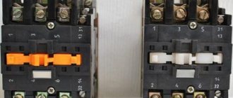
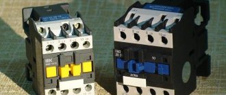
The magnetic starter can be “1”, “2”, “3”, “4” or “5” magnitude. For example, the second magnitude starter PME-211 looks like this:
The names of the starters are deciphered as follows:
- The first sign P is the Starter;
- The second sign M is Magnetic;
- The third character E, L, U, A... is the type or series of the starter;
- The fourth digital digit is the starter size;
- The fifth and subsequent digital characters are the characteristics and types of the starter.
Some characteristics of magnetic starters can be seen in the table
The differences between a magnetic contactor and a starter are very conditional. The contactor performs the same role as the starter. The contactor makes similar connections as the starter, only the electrical consumers have greater power, and accordingly the dimensions of the contactor are much larger, and the contacts of the contactor are much more powerful. The magnetic contactor has a slightly different appearance:
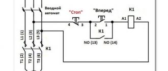
The dimensions of contactors depend on its power. The contacts of the switching device must be divided into power and control. Starters and contactors must be used when simple switching devices cannot control large currents. Due to this, the magnetic starter can be placed in power cabinets next to the power device that it connects, and all its control elements in the form of buttons and push-button switching stations can be located in the user’s work areas. In the diagram, the starter and contactor are indicated by the following schematic sign:
where A1-A2 is the starter electromagnet coil;
L1-T1 L2-T2 L3-T3 power contacts to which the three-phase power voltage (L1-L2-L3) and the load (T1-T2-T3) are connected, in our case an electric motor;
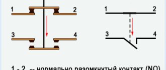
13-14 contacts blocking the engine control start button.
These devices can have electromagnet coils for voltages of 12 V, 24 V, 36 V, 127 V, 220 V, 380 V
When an increased level of safety is required, it is possible to use an electromagnetic starter with a 12 or 24 V coil, and the load circuit voltage can be 220 or 380 V. It is important to know that connected starters for connecting a three-phase motor can provide additional safety in case of accidental loss of voltage in the networks . This is due to the fact that when the current in the network disappears, the voltage on the starter coil disappears and the power contacts open
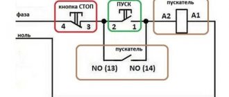
And when the voltage returns, there will be no voltage in the electrical equipment until the “Start” button is activated. There are several circuits for connecting a magnetic starter.
Magnetic starter size
Magnetic starter PM12
For the correct and long-term operation of PME211, it is important that its characteristics (capabilities) correspond to the parameters of the electrical installation in which it is to be used. The most important of these criteria is the maximum permissible current.
For convenience, all starters are divided into 8 values according to load capacity. They are numbered from 0 to 7. Zero-value starters are capable of switching currents up to 6.3 amperes (A). These devices are mostly used in relay protection and automation circuits. 1st size starters are already more powerful. They are capable of controlling currents up to 10 A. The remaining ratios are as follows:
- 0 – 6.3A;
- 1 – 10 A;
- 2 – 25 A;
- 3 – 40 A;
- 4 – 63 A;
- 5 – 100 A;
- 6 – 160 A;
- 7 – 250 A.
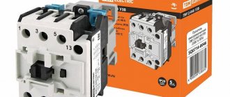
KMI series contactors
Regulatory and technical documentation
In terms of their design and technical characteristics, contactors of the KMI series meet the requirements of Russian and international standards GOST R 50030.4.1,2002, IEC60947,4,1,2000 and have a certificate of conformity ROSS CN.ME86.B00144. According to the All-Russian Product Classification, contactors of the KMI series are assigned code 342600.
terms of Use
Application categories: AC,1, AC,3, AC,4. Ambient temperature – during operation: from –25 to +50 °C (lower limit temperature –40 °C); – during storage: from –45 to +50 °C. Altitude above sea level, no more than: 3000 m. Working position: vertical, with a deviation of ±30°. Type of climatic modification according to GOST 15150.96: UHL4. Degree of protection according to GOST 14254.96: IP20.
When selecting KMI contactors, pay attention to the structure of the symbol
Main technical characteristics
Power Circuit Specifications
Control Circuit Specifications
Connecting the power circuit
Control circuit connection
| Options | Values |
| Flexible cable, mm2 | 1—4 |
| Rigid cable, mm2 | 1—4 |
| Torque when tightening, Nm | 1,2 |
Technical characteristics of built-in auxiliary contacts
| Options | Values | |
| Rated voltage Ue, V | AC current | up to 660 |
| fast. current | ||
| Rated insulation voltage Ui, V | 660 | |
| Thermal resistance current (t°≤40°) Ith , A | 10 | |
| Minimum making capacity | Umin, V | 24 |
| Imin, mA | 10 | |
| Overcurrent protection - fuse gG, A | 10 | |
| Maximum short-term load (t ≤1 s), A | 100 | |
| Insulation resistance, not less, MOhm | 10 |
Contactors of the KMI series can be used to create standard electrical circuits.
Reversing electrical circuit
This circuit is assembled from two contactors and a locking mechanism MB 09.32 or MB 40.95 (depending on the type), designed to prevent the simultaneous activation of contactors.
Electrical circuit "star-delta"
This starting method is intended for motors whose rated voltage corresponds to the delta connection of the windings. Star-delta starting can be used for motors starting without load or with reduced load torque (no more than 50% of the rated torque). In this case, the starting current when connected to a “star” will be 1.8–2.6 A of the rated current. Switching from star to delta must be done after the engine reaches its rated speed.
Design and installation features
Connecting clamps ensure reliable fixation of conductors: – for sizes 1 and 2 – with hardened disc washers; – for sizes 3 and 4 – with a clamping bracket that allows you to connect a contact with a larger cross-section.
There are two ways to install contactors:
- Quick installation on DIN rail:
KMI from 9 to 32 A (dimensions 1 and 2) – 35 mm; KMI from 40 to 95 A (dimensions 3 and 4) – 35 and 75 mm.
- Installation with screws.
KMI series contactors of 3rd and 4th dimensions allow mounting on a 75 mm DIN rail.
KMI series contactors of the 3rd and 4th dimensions are equipped with a hole for a grounding bolt.
dimensions
| Type version | Size, mm | ||
| IN | WITH | D | |
| KMI 10910. KMI 10911 | 74 | 79 | 45 |
| KMI 11210, KMI 11211 | 74 | 81 | 45 |
| KMI 11810, KMI 11811 | 74 | 81 | 45 |
| KMI 22510, KMI 22511 | 74 | 93 | 55 |
Dimensions
KMI 23210, KMI 23211
KMI 34010, MI 34011, KMI 35012, KMI 46512
KMI 48012, KMI 49512
Installation dimensions
Overall and installation dimensions of KMI contactors when mounted on a 35 mm DIN rail
| Type version | Size, mm | ||
| WITH | B | D | |
| KMI 10910, KMI 10911 | 82 | 74 | 45 |
| KMI 11210, KMI 11211 | 82 | 74 | 45 |
| KMI 11810, KMI 11811 | 87 | 74 | 45 |
| KMI 22510, KMI 22511 | 95 | 74 | 55 |
| KMI 23210, KMI 23211 | 100 | 83 | 55 |
Type Size, mmSDKMI 34010, KMI 3401113174KMI 3501213174KMI 4651213174KMI 4801214284KMI 4951214284
Overall and installation dimensions of KMI contactors when installed on a mounting panel or mounting profile
| Type version | Size, mm | |
| WITH | G | |
| KMI 10910, KMI 10911 | 80 | 35 |
| KMI 11210, KMI 11211 | 80 | 35 |
| KMI 11810, KMI 11811 | 85 | 35 |
| KMI 22510, KMI 22511 | 93 | 93 |
| KMI 23210, KMI 23211 | 98 | 98 |
| Type version | Size C, mm |
| KMI 34010, KMI 34011 | 114 |
| KMI 35012 | 114 |
| KMI 46512 | 114 |
| KMI 48012 | 125 |
| KMI 49512 | 125 |
Reversible switching circuit for magnetic starters
The connection diagram for a reversible magnetic starter is used when it is necessary to ensure rotation of the electric motor in both directions. For example, a reversing starter is installed on an elevator, lifting crane, drilling machine and other devices that require forward and reverse movement.
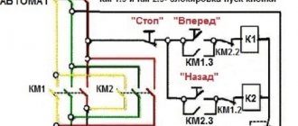
The reversing starter consists of two ordinary starters assembled according to a special circuit. It looks like this:
The connection diagram for a reversible magnetic starter differs from other circuits in that it has two completely identical starters that operate alternately. When the first starter is connected, the engine rotates in one direction, when the second starter is connected, the engine rotates in the opposite direction. If you look closely at the diagram, you will notice that with variable connection of starters, two phases change places. This causes the three-phase motor to rotate in different directions.
To the starter available in the previous diagrams, a second starter “KM2” and additional control circuits for the second starter were added. The control circuits consist of a button “SB3”, a magnetic starter “KM2”, as well as a modified power unit for supplying power to the electric motor. The buttons when connecting a reversing magnetic starter are named “Right”, “Left”, but may also have other names, such as “Up”, “Down”. To protect the power circuits from short circuits, two normally closed contacts “KM1.2” and “KM2.2” were added to the coils, which were taken from additional contacts on the magnetic starters KM1 and KM2. They do not allow both starters to turn on at the same time. In the diagram above, the control and power circuits of one starter are one color and the other starter is a different color, making it easier to understand how the circuit works. When the automatic switch “QF1” turns on, phases “A”, “B”, “C” go to the upper power contacts of the starters “KM1” and “KM2”, and then wait there for switching on. Phase “A” powers the control circuits from the circuit breaker, passes through “SF1” - thermal protection contacts and the “Stop” button “SB1”, goes to the contacts of the “SB2” and “SB3” buttons and remains waiting for a press on one of these buttons . After pressing the start button, the current moves through the auxiliary starting contact “KM1.2” or “KM2.2” to the coil of the starters “KM1” or “KM2”. After this, one of the reversing starters will work. The engine starts to rotate. To start the engine in the opposite direction, you need to press the stop button (the starter will open the power contacts), the engine will turn off power, wait until the engine stops and then press another start button. The diagram shows that the “KM2” starter is connected. At the same time, its additional contacts “KM2.2” opened the power circuit of the coil “KM1”, which will prevent accidental connection of the starter “KM1”.
ROCK
RESPONSIBILITY ÑоÑÑÐ¾Ð¸Ñ ÑлекÑÑомагниÑной ÑиÑÑÐµÐ¼Ñ (ÐÐС), гла RESULTS, RESULTS, RESULTS RESULTS допоР»Ð½Ð¸ÑелÑно ÑÑÑанавливаемом на него блоке конÑакÑов. RESULTS RESULTS Ð © и ÑаÑп¾Ð»Ð¾Ð¶ÐµÐ½Ð° возвѰÑÐ½Ð°Ñ Ð¿ÑÑжина. RESPONSIBILITY й конÑÑÑÑкÑии Ñ ÐºÐ°ÑÑÑкой на ÑÑеднем ÑÑеÑжне collateral, collateral RESULTS RESULTS, RESULTS µ Ñа ÑÑи, из коÑоÑÑÑ ÑоÑÑÐ¾Ð¸Ñ Ð¼Ð°Ð³Ð½Ð¸ÑнÑй пÑÑкаÑелÑ.
RESULTS ROOM ÑÑ ÐºÐ¾Ð½ÑакÑнÑми Ð ¿ÐµÑемÑÑками â они двигаÑÑÑÑÑввеÑÑ-вниз п¿Ñи RESEARCH RESULTS ¶Ð´Ñ Ñобой наÑодÑÑиеÑÑ Ñ Ð¿ÑоÑивоположнÑÑ ÑÑÐ ¾Ñон нижней ÑаÑÑи ÐРвÑоднÑе и вÑÑоднÑе неп одвР¸Ð¶Ð½Ñе главнÑе конÑакÑÑ. RESULTS ROOM ¸ конÑакÑами. RESULTS RESULTS.
Checking the functionality of the magnetic starter and repairing it
The device is checked by supplying power to the control (additional or block contacts). If a working group is closed, its contacts are tested using a multimeter. A short circuit is then triggered to test the protective relay.
Any switching device consists of elements of similar design. Therefore, repair of a magnetic starter is carried out according to the general principle: search for a faulty unit, restoration or replacement.
The mechanical parts (bridge, pressure or return spring) are replaced, the contacts can be cleaned. The control coil is rewound, or the burnt coil is restored by soldering.
Carrying out preparatory work
Before connecting the thermal relay and the magnetic section, you must remember that you are working with an electrical device. That is why, in order to protect yourself from electric shock, you need to de-energize the area and check it. For this purpose, most often, a special indicator screwdriver is used.
The next stage of preparatory work is to determine the operating voltage of the coil. Depending on the manufacturer of the device, you can see the indicators on the body or on the reel itself.
Important! The operating voltage of the coil can be 220 or 380 Volts. If you have the first indicator, you need to know that phase and zero are supplied to its contacts
In the second case, this means the presence of two opposite phases.
The stage of correctly identifying the coil is quite important when connecting a magnetic starter. Otherwise, it may burn out while the device is operating.
To connect this equipment you must use two buttons:
- start;
- stop.
The first of them can be black or green. This button is characterized by permanently open contacts. The second button is red and has permanently closed contacts.
When connecting a thermal relay, it is necessary to remember that the phases are switched on and off using power contacts. The zeros that approach and depart, as well as the conductors that ground, must be connected to each other in the terminal block area. In this case, the starter must be removed. These devices are not switched.
In order to connect a coil whose operating voltage is 220 Volts, you need to take a zero from the terminal block and connect it to the circuit that is intended for the operation of the starter.
Production
The production of PME-211 magnetic starters in Russia has almost ended. Due to difficult economic conditions, the production of contactors has almost ceased, however, over the past five years, several competitive factories have been restored and managed to work at full capacity. This type of starter is gradually beginning to be replaced by cheaper and easier to maintain contactors of both domestic and foreign production.
The starter housing is made of carbolite; this material does not conduct electric current and is the most convenient. The core, as described above, consists of electrical steel plates insulated from each other to avoid the occurrence of eddy currents. The contact and contact surfaces are made smooth to avoid buzzing.
Power and auxiliary contacts are made of brass with silver soldering. Silver helps avoid arcing and also has greater shock resistance during switching on and off.
The retractor coil of the PME-211 magnetic starter is made of copper wire. The diameter of the wire and the number of turns vary depending on the rated voltage at which the starter will operate. It should be remembered that the coil must be supplied with a voltage corresponding to the rated voltage, otherwise the coil will fail in the same way as the contactor itself.
Ð¦ÐµÐ½Ñ Ð½Ð° ÐÐ
OPTIONAL CONDITIONS What's wrong? registry ¸Ñиной ÐÐ. 3rd party RESULTS 490 CONDITIONS. 845 SYSTEM. RESULTS 1160 1650 1160 1650 6-й вои 2500 3780 3780 3780 е 6300 SYSTEM.
Ð ÑÑо можно ÑказаÑÑ Ð¾ÑноÑиÑелÑно ÑеÑии ÐÐÐÐ? What's wrong with you? 3rd party 3rd party Size 560 Size 1600 Size ROOM 6-Ñ Ð²ÐµÐ»Ð¸Ñина ÐÐÐÐÐбез ÑевеÑÑа ÑÑÐ¾Ð¸Ñ Ð¾Ñ 4870 ÑÑÑб UR RUR 34000 SUMMARY. 7-day problem 18 SS. SYSTEM, OPTION 8-й ROOM ÑÑÑ ÑиÑÑо договоÑной.
Magnetic starter connection diagrams.
The first, classic scheme, is intended for the usual start of an electric motor: the “Start” button is pressed - the engine turns on, the “Stop” button is pressed - the engine turns off. Moreover, instead of a motor, you can connect any load, for example, a powerful heating element.
For ease of understanding, the circuit is divided into two parts: power part
and
control circuits
.
Power section
powered by three-phase alternating voltage 380V with phases “A” “B” “C”.
The power part includes: three-pole circuit breaker QF1
, three pairs of power contacts of the magnetic starter
1L1-2T1
,
3L2-4T2
,
5L3-6T3
and a three-phase asynchronous electric.
engine M.
_
Control circuit
receives power from phase “A”.
The control circuit diagram includes the SB1
“Stop” button, the
SB2
“Start” button, the magnetic starter coil
KM1
and its auxiliary contact
13NO-14NO
, connected
in parallel with
the “Start” button.
When turning on the QF1
phases “A”, “B”, “C” arrive at the upper contacts of the magnetic starter
1L1
,
3L2
,
5L3
and are on duty there.
Phase “A”, which supplies the control circuits, comes through the “Stop” button to contact No. 3
of the “Start” button, the auxiliary contact of the starter
13NO
and also remains on duty at these two contacts. The circuit is ready for use.
When you press the “Start” button, phase “A” hits the coil of the KM1
, the starter is triggered and all its contacts are closed.
Voltage appears at the lower power contacts 2T1
,
4T2
,
6T3
and from them is supplied to the electrical circuit. engine. The engine starts to rotate.
You can release the "Start" button and the engine will not turn off, since using the auxiliary contact of the starter 13NO-14NO
, connected
in parallel to
the “Start” button,
self-recovery
.
It turns out that after releasing the “Start” button, the phase continues to flow to the coil of the magnetic starter, but through its 13NO-14NO
. In the lower figure, the arrow shows the movement of phase “A”.
And if there is no self-recovery, you will have to keep pressing the “Start” button all the time while the electric power is working. motor or any other load powered by a magnetic starter.
To turn off email. engine, just press the “Stop” button: the circuit will break, the control voltage will stop flowing to the starter coil, the return spring will return the core with the power contacts to its original position, the power contacts will open and disconnect the engine from the three-phase supply voltage.
Now let's look at the editing room
starter control circuit diagram. Here everything is almost the same as in the circuit diagram, with the slight exception of the implementation of self-retaining.
In order not to pull an extra wire to the “Start” button, a jumper is placed between the coil output and one of the nearby auxiliary contacts: in this case it is “ A2
" and "
14NO
".
And from the opposite auxiliary contact the wire runs directly to contact No. 3
of the “Start” button.
Well, you and I have analyzed a simple classic diagram for connecting a magnetic starter. Also, on one starter you can assemble an automatic transfer switch (ATS) circuit, which is designed to ensure uninterrupted power supply to consumers.
Well, if you have any questions or doubts about the operation of the starter, then watch the video, from which you will additionally obtain the necessary information.
The next circuit will be a little more complicated than this one, since it will involve two magnetic starters and three buttons and this circuit is called reversible. Using such a scheme, it will be possible, for example, to rotate the engine left or right, raise and lower the winch.
Until then, goodbye. Good luck!
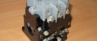
Magnetic starter
The magnetic starter PME-211 consists of a collapsible housing, an electromagnet, contacts, both power and auxiliary (locking). In the lower part of the carbolite body there is a core with a retractor coil. At the top there are power contacts, which are connected to the movable core and when the coil is triggered, they are retracted, thereby closing the power contacts. The PME-211 magnetic starter also has auxiliary contacts, or, as they are also called, blocking contacts. When the power ones close, they block power to the contactor coil. This eliminates the need to constantly press the start button.
The magnetic starter has a protective cover on top that covers the power contacts. The core consists of layers of special ferromagnetic steel, interconnected into a single shape.
Purpose of magnetic starters PME-211
The direct and most common purpose of magnetic starters is to start powerful three-phase electric motors. Using several starters, you can get a reverse circuit. With this connection, two devices are involved in the operation. The direction of rotation of the motor will depend on which one is currently turned on. Similar assemblies are also sold ready-made. They must have a mechanical or electrical interlock. This system prevents the simultaneous activation of both starters. Otherwise, an interphase short circuit will occur, which can lead to equipment failure. Using PME 211, the reverse connection diagram is shown below.
Additional Information. The direction of rotation of an asynchronous motor depends on the phase sequence. That is, if you swap any two of them (L1 and L3 or L1 and L2), the drive will start moving in the other direction. The operation of the reverse circuit is based on this property of engines. When the 1st starter is turned on, there is one phase order, when the 2nd starter is turned on, there is another.
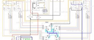
Another connection of starters is three-phase motor protection. It ensures the safe operation of the latter. To power an electric motor, it is necessary to have three phases, i.e. L1, L2 and L3. If one of them is missing, for example, due to a broken cable or burnt contacts of the starter, the drive windings will inevitably fail. To prevent such an emergency situation, a circuit with three magnetic starters is used. It is assembled in such a way that if any of the three phases are lost, the remaining two are automatically turned off. The engine simply stops, but remains operational.
Features of connecting PME-211 starters
Any contactor or magnetic starter, incl. PME211 should be used based on the characteristics for which it is designed. The main ones include control voltage and current. However, the requirements do not end there.
The operating conditions of the magnetic starter must meet the requirements of the “Rules for the technical operation of electrical installations by consumers.” Even the altitude above sea level is regulated. In normal mode, it should not exceed 2,000 m. At altitudes from 2 to 4.3 km, the operating current should be limited by 10%. In this case, the PME211 magnetic starter is mounted on a vertical surface with a maximum deviation from this position of no more than 90°. Its contact connectors must be clean and have a characteristic metallic sheen.
At the moment the magnetic starter is triggered, a mechanical impulse passes through its entire volume. This is caused by the “impact” of its contacts and the halves of the magnetic circuit. Therefore, such a device is subject to vibration. For this reason, it is advisable to connect flexible mounting wires in soft insulation to the magnetic starter. Rigid monolithic ones break off relatively quickly. The situation is further complicated by the fact that the location of such a break is usually hidden under insulation and is not visible visually.
Additional functions
When the magnetic starter itself is not enough to assemble the required circuit, additional equipment is used that is designed to expand the capabilities of this device. The most commonly used third-party peripherals are:
- Thermal relay. Serves to protect motors from overcurrent. If the latter is exceeded, the magnetic starter will turn off after a specified time. This, in turn, will stop the engine and prevent its failure.
- Additional block contacts. Used to connect the starter to third-party devices (alarm).
- Indicator lamps. Inform the equipment operator about the on or off state of the starter, respectively, the engine or other load.
Blocking contacts
The PME211 magnetic starter has established itself as one of the most successful solutions for controlling motors with power up to 11 kW. A wide range of control voltages and the ability to connect additional equipment allow you to solve problems of any complexity with its help.
Starter 220 V
The magnetic starter PME-211 for 220 V has a pull-in coil with a rated supply voltage of 220 V. This means that the control network voltage must also be 220 V. Basically, such starters are used to control the connection of low-power motors and heating devices that require the use of contactor.
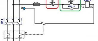
Magnetic starter connection diagram
The diagram contains the following elements:
QF – circuit breaker contacts
KM1 – magnetic starter contacts
P – thermal relay. Provides overload protection
M – electric motor
If you use a magnetic starter connection diagram for an asynchronous electric motor (circulating or sharpening machine, compressor), then you need to know that a three-phase load (electric motor) may fail if additional protection is not installed. For example, one wire is burnt out, and the electric motor operates on two phases, this is called “single-phase operation,” which can lead to burnout of the motor windings. In this case, only thermal protection will prevent the electric motor from “burning out”. This is a thermal relay or thermal release of a circuit breaker, but correctly selected. Monitor the choice of thermal protection and the rated current of the circuit breaker. If the electric motor is 2.2 kW, then it is unlikely that a 25 A circuit breaker will protect against overload and most likely the electric motor will burn out.
If the electric motor does not rotate in the desired direction, then it is necessary to change the phase order on the starter or circuit breaker. If three phases A, B and C were connected to the machine, then make connections B, A and C. In the same way, self-propelling of a three-phase induction electric meter is eliminated.
If it is necessary to turn on the electric motor in different directions, then install a reverse start. This could be a beam crane in a workshop where it is necessary to rotate the electric motor in both directions.
Connection features
The PME-211 magnetic starter is connected depending on the requirements of the circuit and technical conditions. A single connection is made provided that there is no need for reverse switching. Typically a single connection is used to control heating elements.
With a reverse connection, two paired magnetic starters are connected by wires so that when you press the start button, the engine begins to rotate in a certain direction, depending on which starter is triggered. This connection diagram is called reversible and is widely used when assembling control circuits on almost all machine-building equipment. With this scheme, blocking contacts protect against simultaneous activation of magnetic starters, which can damage the motor.
Often, magnetic starters are connected in tandem with a thermal relay that protects equipment from overloads and loss of one phase. The thermal relay is structurally designed so that a mechanical connection with a magnetic starter is possible. The relay has a bimetallic plate, which heats up when the current increases and bends and turns off the power to the starter coil, thereby breaking the power circuit.
In control circuits with magnetic starters, fuses and circuit breakers are also used for protection. Thermal relays have special adjustment of the operating current. Over time, it is necessary to add value, since the equipment wears out and this adjustment is necessary to avoid constant tripping, but do not forget that with an increase in the tripping current, the motor can be damaged.