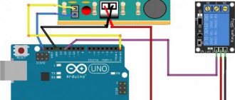
An electromagnetic starter is a low-voltage combined electromechanical device specialized for starting three-phase electric motors, to ensure their continuous operation, to turn off the power, and in some cases to protect the electric motor circuits and other connected circuits. Certain engines have a motor reverse function.
In essence, an electromagnetic starter is an improved, modified contactor. But more compact than a contactor in the usual sense: lighter in weight and designed directly for working with motors. Certain modifications of magnetic starters are optionally equipped with a thermal microrelay for emergency shutdown and protection against phase loss.
To control the start of the motor by closing the contacts of the device, a key or a low-current group of contacts is intended:
- with a coil for a certain voltage;
- in some cases, both.
In the starter, the coil in the metal core is directly responsible for switching the power contacts, to which the armature is pressed, pressing on the contacts and closing the circuit. When the power to the coil is turned off, the return spring moves the armature to the opposite position - the circuit opens. Each contact is located in a special arc-extinguishing chamber .
What is the difference between a magnetic reversing starter circuit: configuration rules
Let's imagine that there is a need to understand the features of a device in which an electric motor is capable of operating in two directions - forward and reverse, that is, reversible. And if such a feature is obvious, it means that the circuit of the unit provides for the presence of a magnetic reversing starter. Its use is not so simple; it is necessary to consider the operating mode in order to prevent dangerous phase short circuits.
In the diagram you can definitely find the designation of an additional control circuit and a reverse start button. Due to such thoughtfulness, the created circuit is reliable, as it is protected from short circuits.
What causes the reverse? This is easy to explain. – Due to the reversal of the two phases present in the system: when one stops working, and the other, on the contrary, starts. For more reliable protection, a blocking must be thought out in the circuit, which is responsible for the accurate and timely stopping of one of the starters, the first or the second. It all depends on the tasks assigned. Let us remind you that if two starters are triggered, a short circuit will instantly occur on the power contacts of the unit.
Note that the reverse movement does not start instantly, since the activation of several important points is required. Firstly, it is definitely recommended to stop the engine and press the “Stop” button
Secondly, you need to pay attention to the condition of the coil, remove the voltage from it, otherwise the reverse starting process will fail. If everything is done correctly, the starter will return to its original position under the action of the spring
That's it, the unit is ready for reverse. We press the “Start” button, accordingly, the required voltage is supplied to the coil, which means the process has started. From the control panel of the device you can read information about the closure of the electrical circuit. This means that current has entered the system, and it is gradually supplied to the coil. At the same time, all contacts that have not started working are blocked. Security requires this.
Please note that if the thermal relay is triggered, the unit will stop to avoid an emergency.
Thus, the magnetic starter plays an important role in the operation of motors. The reversing starter also deserves its place, ensuring uninterrupted operation of machines, heating elements, elevators and other electrical equipment. The starters are reliable and safe, especially if they are additionally equipped with system locking mechanisms. They are located inside the casing and do not allow two coils to operate simultaneously, without leading to a phase short circuit.
{SOURCE}
Theoretical basis
The type of engine reverse starting circuit depends on the following factors:
- type of electric motor;
- supply voltage;
- purpose of electrical equipment.
Therefore, reverse circuits can vary greatly, but once you understand the principles of their construction, you can assemble or repair any similar circuit.
Before disassembling engine reverse circuits, you need to decide on the concepts that will be used to describe the work:
- A normally open (open) contact is a contact that is in an open state without external influence. By external influence, first of all, we mean the supply of voltage to the control coil of a relay or magnetic starter. In the case of buttons, contact switching is done mechanically.
- A normally closed (closed) contact is a contact that is in a closed state without the influence of external forces.
- A magnetic starter is an electromagnetic device that has three power normally open contacts and several auxiliary contacts. When supply voltage is applied to the electromagnet coil, the armature is attracted and all contacts switch simultaneously. Power contacts are used to connect the electric motor to the network, and auxiliary contacts are needed to build a control circuit, so they can be normally open or closed. After removing the control voltage, under the action of springs the device returns to its original state.
- A reversing starter is two identical magnetic starters, mounted on the same base, with a common body. The device is designed for reversing three-phase motors, so the power contacts are connected to each other in a certain way.
- Thermal relay is a device to protect the motor from overheating caused by increased currents in the windings.
- A contactor is a switching device in many ways similar to a magnetic starter. But unlike it, it can have from two to four normally open power contacts with arc-extinguishing chambers and is designed for switching large currents.
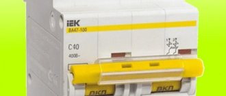
- A circuit breaker is a device for protection against short circuit currents.
In order for an electric motor to change its rotation, its magnetic field must be changed. To do this, it is necessary to make some switchings, which depend on the type of electrical machine .
Changing Rotational Movement
Now, to give the opposite direction of movement, you need to change the position of the power phases, which is convenient to do using the KM2 switch.
Everything happens thanks to the opening of the first phase. In this case, all contacts return to their original position, de-energizing the motor winding. This phase is the standby mode.
Using the SB3 button activates a magnetic starter with the abbreviation KM2, which, in turn, changes the position of the second and third phases. This action causes the motor to rotate in the opposite direction. Now KM2 is the leader and until it opens, KM1 will not be used.
Principle of operation
An electric motor is a mechanism in which rotation is carried out under the influence of electromagnetic waves. It is based on only two components:
Only the first element rotates, and the impulse is supplied to it from the second element. The higher the engine power, the larger its dimensions. From all the variety there are:
In commutator-type motors, power is supplied to the rotor through carbon brushes that touch the commutator lamellas. Such motors are also called squirrel-cage motors. In asynchronous motors, the operation scheme is somewhat different. In this case, rotation occurs under the influence of two forces:
The voltage from the power source is supplied to the fixed stator windings. At the same time, electromagnetic waves arise in it. If the voltage is variable, then the magnetic field is unstable and has certain fluctuations. Thanks to these vibrations, the rotor shifts. There is a small air gap between the rotor and stator, thanks to which unhindered displacement is possible. Magnetic waves from the stator windings affect the rotor windings, creating voltage. Due to this effect, electromotive force or EMF arises. It causes magnetic waves to interact in the opposite direction with what is in the stator, which is why the motor is called asynchronous.
Read also: LED lamp started blinking repair
Specifications
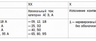
We will not consider all the parameters of the device here, because the choice is always made based on the size of the starter, which is characterized by the rated load current acting on the contacts of the device. There are seven starter values, each of which corresponds to the permissible current load. The photograph below shows these same values and in what areas such magnetic starters are used.
It should be noted that small errors in the parameters are acceptable. But in some cases it is necessary to take into account the range in which the thermal relay operates. If the starters have an overestimated load, and the relays have an underestimated minimum thermal shutdown value, then there may be a mismatch with the specified power of the electrical circuit or consumer.
{SOURCE}
DC machines
Reversing starting of a DC motor can be accomplished by changing the polarity of the connection of the armature winding or field winding. Depending on how these two windings are connected, DC motors have the following types of excitation:
- independent - the field and armature windings are powered from different sources;
- sequential;
- parallel;
- mixed.
DC motors can run out - a condition of machine operation in which the speed increases so much that it causes mechanical damage.
When using a commutator motor with parallel or independent excitation, this mode may occur when the excitation winding breaks. Therefore, the connection diagram of the reversible motor in this case is constructed in such a way that the armature winding is switched, and the field winding must be directly connected to the power source. That is, it is unacceptable to connect the excitation circuit through any contacts or fuses.
Otherwise, the control circuit differs from the reversible connection of a three-phase motor only in that two DC supply wires are switched instead of three AC phases.
Magnetic starter connection diagrams.
The first, classic scheme, is intended for the usual start of an electric motor: the “Start” button is pressed - the engine turns on, the “Stop” button is pressed - the engine turns off. Moreover, instead of a motor, you can connect any load, for example, a powerful heating element.
For ease of understanding, the circuit is divided into two parts: power part
and
control circuits
.
Power section
powered by three-phase alternating voltage 380V with phases “A” “B” “C”.
The power part includes: three-pole circuit breaker QF1
, three pairs of power contacts of the magnetic starter
1L1-2T1
,
3L2-4T2
,
5L3-6T3
and a three-phase asynchronous electric.
engine M.
_
Control circuit
receives power from phase “A”.
The control circuit diagram includes the SB1
“Stop” button, the
SB2
“Start” button, the magnetic starter coil
KM1
and its auxiliary contact
13NO-14NO
, connected
in parallel with
the “Start” button.
When turning on the QF1
phases “A”, “B”, “C” arrive at the upper contacts of the magnetic starter
1L1
,
3L2
,
5L3
and are on duty there.
Phase “A”, which supplies the control circuits, comes through the “Stop” button to contact No. 3
of the “Start” button, the auxiliary contact of the starter
13NO
and also remains on duty at these two contacts. The circuit is ready for use.
When you press the “Start” button, phase “A” hits the coil of the KM1
, the starter is triggered and all its contacts are closed.
Voltage appears at the lower power contacts 2T1
,
4T2
,
6T3
and from them is supplied to the electrical circuit. engine. The engine starts to rotate.
You can release the "Start" button and the engine will not turn off, since using the auxiliary contact of the starter 13NO-14NO
, connected
in parallel to
the “Start” button,
self-recovery
.
It turns out that after releasing the “Start” button, the phase continues to flow to the coil of the magnetic starter, but through its 13NO-14NO
. In the lower figure, the arrow shows the movement of phase “A”.
And if there is no self-recovery, you will have to keep pressing the “Start” button all the time while the electric power is working. motor or any other load powered by a magnetic starter.
To turn off email. engine, just press the “Stop” button: the circuit will break, the control voltage will stop flowing to the starter coil, the return spring will return the core with the power contacts to its original position, the power contacts will open and disconnect the engine from the three-phase supply voltage.
Now let's look at the editing room
starter control circuit diagram. Here everything is almost the same as in the circuit diagram, with the slight exception of the implementation of self-retaining.
In order not to pull an extra wire to the “Start” button, a jumper is placed between the coil output and one of the nearby auxiliary contacts: in this case it is “ A2
" and "
14NO
".
And from the opposite auxiliary contact the wire runs directly to contact No. 3
of the “Start” button.
Well, you and I have analyzed a simple classic diagram for connecting a magnetic starter. Also, on one starter you can assemble an automatic transfer switch (ATS) circuit, which is designed to ensure uninterrupted power supply to consumers.
Well, if you have any questions or doubts about the operation of the starter, then watch the video, from which you will additionally obtain the necessary information.
The next circuit will be a little more complicated than this one, since it will involve two magnetic starters and three buttons and this circuit is called reversible. Using such a scheme, it will be possible, for example, to rotate the engine left or right, raise and lower the winch.
Until then, goodbye. Good luck!
To a single-phase network
At home, you often have to use an asynchronous motor, but not every household has a three-phase network, so it is important to know how to connect the motor to a single-phase network. To start from one phase, an additional impulse is required; to provide it, a capacitor of the required capacity is selected. To put it simply, there should be two capacitors. One of them is the starting one and is connected in parallel with the first. The connection of the motor windings is carried out according to the “star” circuit. If the windings are connected in a different way and there is no way to change it, then it will not be possible to complete the required circuit.
In order for the reversible circuit to function, it will be necessary to switch the power that comes from the capacitors between the poles. You will need two switches and one non-fixed button. One of the switches will be responsible for supplying voltage to the engine power circuit. The second switch must have three positions. In one of them it will be turned off, and in the other two it will change the power supply from the capacitors to the windings. A non-fixed button will additionally connect a second capacitor when the engine starts.
The two terminals of the capacitor are connected to each other. The start button is connected to the other two. The middle terminal of the three-position switch is connected to the capacitors in the place where they are connected to each other. The other two pins are connected to the motor terminals, which receive power. Capacitors are connected to the output of the winding, which is used for starting. The power button is placed in the break of the phase wire.
To power the entire mechanism, it is necessary to supply power to the motor circuit using the main switch. After this, the direction of rotation of the engine is set using a three-position switch. Next, the start button is pressed until the engine reaches operating speed. If there is a need to change the direction of rotation, then you will need to de-energize the engine and wait until it stops completely, switch the three-position toggle switch to the opposite extreme position and repeat the process.
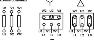
Starter capabilities
To limit the starting current of a three-phase motor, its windings can be connected in a star, then, if the motor has reached its rated speed, switch to a delta. In this case, magnetic starters can be: open and in a housing, reversible and non-reversible, with and without overload protection.
Each electromagnetic starter has blocking and power contacts. Power switches loads. Interlocking contacts are needed to control the operation of the contacts. Blocking and power contacts can be naturally open or normally closed. In circuit diagrams, contacts are shown in their normal state.
The ease of use of reversing starters cannot be reviewed. This includes operational control of three-phase asynchronous motors of various machines and pumps, and control of the ventilation system, fittings, right down to the locks and valves of the heating system. The possibility of remote control of starters is especially noteworthy if the electrical source of remote control switches the starter coils in a similar way to relays, and the latter safely connect power circuits.
Reversing and non-reversing starters
Devices come in various types and perform all assigned tasks.
There are two types of starters:
- irreversible;
- reversible.
In a reversing starter, there are two individual magnetic devices in one housing, electrically connected to each other and attached to a common base, but only one of these starters can function - either only the first, or only the second.
The reversible device is inserted through naturally closed blocking contacts, the role of which is to eliminate the synchronous activation of two groups of contacts - reversible and non-reversible, so that an interphase short circuit does not occur. Certain modifications of reversing starters are protected to provide the same function. It is possible to switch the power phases in turn so that the main function of the reversible starter is performed - changing the direction of rotation of the electric motor. The order of phase alternation has changed - the direction of the rotor has also changed.
More about deadlock
The electrical circuit for reversing starting of an asynchronous motor requires an interlock. It is worth understanding that to change the direction of rotation of an asynchronous motor, you need to swap any 2 phases. To do this, the starter inputs are connected directly, and the output is connected crosswise across any 2 phases. If both starters are turned on at the same time, a short circuit will occur, which will most likely burn out the power contact groups on the starters.
You may be interested in: Boyle-Mariotte Law: formula and example problem
In order to avoid a short circuit when installing a reversible motor start, it is necessary to prevent the simultaneous operation of both starters. This is why it is necessary to use an interlocking scheme. When the first starter is turned on, the power to the second starter is interrupted, which prevents its accidental activation, for example, both “start” buttons are pressed simultaneously.
If it turns out that when you press the button that should turn on “rotation to the right,” the engine rotates to the left, and, conversely, when you press “rotation to the left,” the engine rotates to the right, you should not reassemble the entire circuit. Just swap 2 wires at the input - that's all, the problem is solved.
It may happen that this is impossible to do at the input due to some circumstances. In this case, swap the 2 wires in the brand box on the engine. And again the problem is solved. The right spin button will spin right, and the left spin button will spin left.
Reversing diagram of a three-phase motor in a single-phase network
Since a three-phase asynchronous motor will lack two phases, they need to be compensated with capacitors - starting and running, to which both windings are switched. The torsion of the shaft in one direction or another depends on where to attach the third.
The diagram below shows that winding number 3 is connected through a working capacitor to a three-position toggle switch, which is responsible for the forward/reverse engine operating modes. Its other two contacts are combined with windings 2 and 1.
When turning on the engine, you must adhere to the following algorithm of actions:
- Apply power to the circuit through a plug or switch.
- Move the toggle switch to switch operating modes to forward or reverse (reverse).
- Set the power switch to the ON position.
- Press the “Start” button for a time not exceeding three seconds to start the engine.
Description of the operation of the above circuit
You may be interested in: Lictor is: the essence of the profession and historical facts
Let's analyze the operation of the circuit diagram of reverse engine starting. The current flows from phase C to the normally closed common button KnS, the “stop” button. After which it passes through a general current relay, which will protect the engine from overloads. Then, when you press the switch “right”, the current passes through the normally closed contact of the KM2 starter. Entering the coil of the KM1 starter, the core is retracted, closing the power contacts, breaking the power to the KM2 starter.
This must be done in order to interrupt the power supply to the second starter and protect the circuits from short circuits. After all, reverse is ensured by the fact that any 2 phases change places. Thus, if you press the “left” KnP button when KM1 is turned on, the start will not occur. Self-shunting is provided by an auxiliary contact, shown under the “right” control panel. When the starter is turned on, this contact is also closed, providing power to the starter coil.
In order to stop the engine, you must press KnS (“stop”), as a result of which the starter coil will lose power and return to normal. Now that KM1 has returned to its normal state, it has closed the normally closed group of auxiliary contacts, thanks to which the KM2 starter coil can again receive power, and it has become possible to start rotation in the opposite direction. To do this, press the control button “left”, thereby turning on the KM2 starter. Receiving power, the coil draws in the core and closes the power contacts, turning on power to the motor, swapping 2 phases.
Analyzing the operation of this circuit for reversing engine starting, you can notice that the bypass is provided by a normally open auxiliary contact, shown under the “left” switchgear button, and it cuts off the power to the KM1 starter, making it impossible to turn it on.
The circuit for a three-phase drive was discussed above. At the very beginning of the circuit, immediately after the KnS, you can see a normally closed contact from the current relay. If the motor consumes excessive current, the relay is activated, cutting off power to the entire control circuit. Everything that works in the control circuit will lose power, this will save the engine from failure.
Schematic diagram
In the illustration above you can see a schematic diagram of a reversible motor connection. It differs from the usual one only in the presence of an additional module. To be more precise, the circuit uses two control modules. One of them causes the engine to rotate to the right, and the other to the left. The operator interacts with the modules using the SB2 and SB3 buttons. The Latin letters A, B, C in the diagram indicate the supply lines of a three-phase network. They fit into a common switch, which is designated QF1. Next come two contactors KM and a digital designation. From the contactors the circuit goes to the motor windings. Each of these contactors is displayed separately and is located on the right, where you can further examine their components.
General diagram of electric motor reverse
Various types of three-phase asynchronous electric motors are widely used in industry and agriculture. They are installed in electric drives of equipment and serve as an integral part of automatic devices. Three-phase units have gained popularity due to their high reliability, simple maintenance and repair, and the ability to operate directly from the AC mains.
The specific operation of devices operating with electric motors requires a change in the direction of shaft rotation, called reverse. For such situations, special circuits have been developed, which include additional electrical devices. First of all, this is an input machine that has the appropriate parameters, contactors (2 pcs.), a thermal relay and controls in the form of three buttons combined into a common push-button station.
In order for the shaft to start rotating in the opposite direction, it is necessary to change the phase arrangement of the supplied voltage. Constant monitoring of the voltage supplied to the electric motor and contactor coils is necessary. The direct implementation of reverse in a three-phase motor is carried out by contactors (CM) No. 1 and No. 2. When contactor No. 1 is activated, the phases of the incoming voltage will be located differently than when contactor No. 2 is activated.
To control the coils of both contactors, three buttons are provided - FORWARD, BACK and STOP. They provide power to the coils depending on the phase arrangement. The order in which the contactors are turned on affects the closure of the electrical circuit in such a way that the rotation of the motor shaft in each case occurs strictly in a certain direction. The BACK button only needs to be pressed, but not held, since it itself turns out to be in the desired position under the action of self-retaining.
All three buttons are locked to prevent them from being activated at the same time. Failure to comply with this condition may result in a short circuit in the electrical circuit and equipment failure. To block the buttons, a special contact block located in the corresponding contactor is used.
Push-button adjustment station
Let's imagine another vision for implementing reverse - for a push-button station. This element is responsible for providing reverse in three-phase electric motors and has all the features characteristic of a controlled component. Each such system has push-button contacts of a specific layout, which, in fact, are connected into a single push-button post.
The operating principle of this unique system has many common characteristics with the operating process of other elements of the control circuit (including the reverse one). The magnetic starter contactor is started using a control pulse, which arrives immediately after pressing the “Start” button. This button is responsible for quickly applying voltage to the copper control coil.
Wiring diagram push-button post
When switched on, the contactor can operate for a long period of time. This feature became possible thanks to the application of the self-retaining principle. Its essence is to connect an additional contact in parallel to the start button in order to reliably supply voltage to the winding. This feature allows you to simply press the Start key and not hold it afterwards.
As a result, the magnetic starter is turned off only after the coil control circuit is broken. This feature creates another need - the presence of a button with an open contact. Based on this, all control keys included in the push-button station are equipped with two pairs of contacts:
- NO – normally open;
- NS - normally closed.
The buttons are manufactured in universal versions in order to ensure instant motor reverse at any time when the need arises.
The shutdown key is marked “Stop” and colored red. To turn on reverse, you need to press “Back” on the remote control (if you just need to start, just “Start” or “Forward”).
Also, it is worth noting that the push-button station is actively used when implementing a non-reversible engine operation scheme, that is, when the shaft turns only in one direction.
Operating principle of a reversing magnetic starter
The reversing magnetic starter is connected and operates as follows. After the “start” command is executed on the device’s control panel, the electrical circuit is closed, as a result of which current is supplied to the coil. At this time, the mechanical blocking system is activated, thus blocking unused contacts. Since the contacts of the button are also blocked, this action allows you not to hold the button, but to calmly release it. The second button of the reversing magnetic starter, in parallel with starting the device, opens the circuit, so its activation will not give any result.
To carry out the reverse, it is necessary to activate the “stop” button, pressing which will de-energize both coils of the reversing magnetic starter, thereby stopping the functional operations of the equipment. With this action, all blocking devices will take their original position. This sequence allows you to activate the reversing magnetic starter again, without any additional actions. When you select the “start” command, the above actions will occur, but the second coil will be used, and the first will be blocked.
The most advanced and safe reversing magnetic starter is equipped with additional locking system mechanisms. These devices are placed to block the operating torque, usually inside the casing (directly under the control panel) and are designed to prevent both coils from operating at once. According to the diagram of a reversing magnetic starter, if it is equipped with an electrical interlocking system, then the use of mechanical interlocks is not at all necessary.
Reverse occurs through a complete stop of the engine. In other words, when a reversing magnetic starter is triggered, the motor slows down, followed by a complete stop, and then rotates in the other direction. However, in this case it is necessary to match the power of the engine and the reversible magnetic starter. Only when this process is carried out will the reverse be carried out correctly.
If stopping and reversing the engine is carried out by back switching, then the power of the equipment should be significantly lower than the maximum permissible power of the reversing magnetic starter. Most often, the engine is 1.5-2 times inferior in power to the starter. In many ways, the difference in power depends on the quality of the contacts of the magnetic starter, or rather their wear resistance when operating under these conditions.
This mode must be carried out without the use of mechanical locking systems. However, the safety of operation of a reversing magnetic starter must be ensured by the use of electrical interlocking systems. In general, reversible magnetic starters are a technologically advanced and safe method for remote control of asynchronous electric motors.
Operating principle of an asynchronous motor
The electric motor can operate in both three-phase and single-phase modes . The operating principle of the circuits changes slightly, but there are some additions to the power supply from a single-phase network.
Three-phase network
The electrical circuit diagram of the reversible start of a three-phase electric motor with a squirrel-cage rotor is as follows (the diagram is shown in Fig. 1) The entire circuit is powered from a three-phase alternating current network with a voltage of 380 V through an automatic circuit breaker.
In order to reverse such an electric machine (M), you need to change the alternation of any two phases connected to the stator. In the diagram, magnetic starter Mn1 is responsible for forward rotation, and Mn2 is responsible for reverse rotation. The figure shows that when Mp1 is turned on, the phases on the stator A, B, C alternate, and when Mp2 is turned on - C, B, A, that is, phases A and C change places, which is what we need.
When voltage is applied to the circuit, the coils Mp1 and Mp2 are de-energized. Their power contacts Mn1.3 and Mn2.3 are open. The electric motor does not rotate.
When you press the Start1 button, power is supplied to the MP1 coil, the starter is triggered and the following happens:
- The power contacts of Mn1.3 close, the supply voltage is supplied to the stator windings, and the motor begins to rotate.
- The normally open auxiliary contact Mn1.1 closes. This contact ensures self-locking of the MP1 starter. That is, when the Start1 button is released, the Mn1 coil will remain energized thanks to the Mn1.1 contact and the starter will not turn off.
- The normally closed auxiliary contact Mn1.2 opens. This contact breaks the control circuit of the Mp2 coil, thus providing protection against the simultaneous activation of both contactors.
If there is a need to stop the engine or reverse , you need to press
Stop button. In this case, the power circuit Mn1 opens, the contactor is turned off, its contacts return to their original state shown in the figure, and the electric motor stops.
In order for the engine to start rotating in the opposite direction, you need to press the Start button2. By analogy with Mp1, contacts Mp2.3, Mp2.1, Mp2.2 will operate, a phase switch will occur on the stator winding and the motor will begin to rotate in the opposite direction.
The control circuit is powered from two phase wires. With this connection, contactors with 380 V coils must be used. Fuses Pr1 and Pr2 provide protection against short circuit currents. In addition, removing these fuses completely de-energizes all controls and avoids the risk of electrical injury during maintenance and repair.
Protection of the electrical machine from overloads is provided by thermal relay RT . When an increased current flows in any of the three stator windings, the bimetallic plate RT heats up, causing it to bend. At a certain current, the plate heats up so much that its bending causes the thermal relay to operate, due to which it opens its normally closed contact PT in the control circuit of the coils Mp1 and Mp2 and the motor is disconnected from the network.
The response time depends on the current value: the higher the current, the shorter the response time. Due to the fact that the RT operates with a certain delay, inrush currents, which can be 7-10 times higher than the rated ones, do not have time to trigger the protection.
Depending on the type of device and settings, after the thermal relay is triggered, there are two options for returning the circuit to working condition:
- Automatic - after the sensitive element has cooled, the relay returns to its normal state and the engine can be started with the Start button.
- Manual - you need to press a special flag on the RT body, after which the contact will close and the circuit will be ready to start.
The considered three-phase motor reverse circuit can be modified depending on conditions and needs. For example, the control circuit can be powered from a 12 V network, in which case all control elements will be under safe voltage and such an installation can be safely used in high humidity.
Reversing the motor can only be done when the motor is completely stationary, otherwise the starting currents will increase several times, which will lead to the protection being triggered. In order to monitor the fulfillment of this condition, time relays can be added to the control circuit, the contacts of which are connected in series to MP2.2 and MP1.2. Thanks to this, after pressing the Stop button, the engine can be started in the opposite direction only after a few seconds have passed, which are necessary to completely stop the mechanism .
Single phase mode
In order for a three-phase asynchronous motor with a squirrel-cage rotor to operate from a single-phase 220 V network, a connection diagram with starting and running capacitors is used.
Three wires come from the stator winding of the electric motor. Two wires are connected directly to the phase and neutral wires, and the third is connected to one of the supply wires through a capacitor. In this case, the direction of rotation depends on which of the supply conductors the capacitor is connected to.
If you want to turn such a connection diagram into a reversible one, it needs to be supplemented with a toggle switch that will switch the capacitance from one power wire to another.
Magnetic starter device for reverse starting
A standard starter consists of the following components:
- a core with an induction coil attached to it;
- anchor with a mechanism for moving contact groups;
- a housing that ensures structural integrity along with protection from external influences.
When the supply current is supplied (switched off), the movement of the armature closes (disconnects) the corresponding contacts of the power circuits. Reversible modifications are created from two conventional starters installed on one mounting panel. Additional conductors provide blocking that prevents two products from being turned on at the same time.
Reversing starter
In this embodiment, separate keys are used that initiate rotation of the rotor in the forward and reverse directions. The first operating mode is accompanied by shunting of the corresponding circuit by the “KM1” contact group. If you press the Back key after this, nothing will happen.
To activate reverse rotation, you must first stop the engine to avoid damage. By pressing “Stop” (C – in the figure below), the supply voltage of 380 V is turned off. Afterwards, you can supply current to the required windings through the power contact groups “KM2”.
Connection diagram
Design and principle of operation
Magnetic contactors or starters refer to switching devices that remotely start electric motors and other equipment.
The design and circuit of these devices is very similar to an electromagnetic relay. An important additional function is the ability to promptly connect and disconnect a three-phase load. The main structural element is a magnetic core made in the shape of the letter W. The material used was electrical steel in the form of thin sheets.
Read also: Formulas for serial and parallel connections
The core itself consists of two halves, one of which is stationary and is fixed to the base of the device. The other part - the movable one - in the absence of current is held at a certain distance from the fixed part by a spring. This creates an air gap between both parts.
The starter is controlled through a coil placed on the central rod of the core, located in the stationary part. Contacts are attached to the moving magnetic circuit through a bridge connection. At the moment the starter is triggered, these bridges move simultaneously with the magnetic circuit and make a short circuit with the fixed contact group.
The starting device is triggered after voltage is applied to the control coil. An electromagnetic force arises, under the influence of which the moving part of the core is attracted to the stationary part. As a result, the power contact groups become closed, and current begins to flow to the output terminals. After the voltage supply is stopped, the coil is de-energized and the moving part returns to its place. At this moment, the return spring is activated, ensuring the opening of the contacts.
During switching off, a double gap is formed at each pole of the contacts, facilitating more efficient extinguishing of the electric arc. The function of the arc chute is performed by the device cover, under which the contacts are located.
The starter has not only the main contact group, but also an additional one - in the form of block contacts, used for auxiliary purposes. They are mainly used in control, signaling and blocking circuits.
Protection of power circuits from short circuits or “fool proof”.
As we already know, before changing the rotation of the engine, it must be stopped. But it doesn’t always work out this way, since no one is immune from mistakes. Now imagine a situation where there is no protection.
The engine rotates to the left, starter KM1
in operation and from its output, all three phases go to the windings, each to its own.
Now, without turning off the KM1
, we turn on the
KM2
.
Phases “B” and “C”, which we swapped places for reverse, will meet at the output of the KM1
.
An interphase short circuit
will occur between phases “B” and “C”.
To prevent this from happening, the scheme uses normally closed
starter contacts, which are installed in front of the coils of the same starters, and thus eliminate the possibility of turning on one magnetic starter until the other is de-energized.
Motor protection when reverse is engaged
The main thing to remember here is that switching to reverse movement and any work associated with power contacts and changing their position are carried out only after de-energizing the power unit and stopping the movement of the working part of the mechanism. Thanks to the normally closed contacts included in the connection diagram, the possibility of a phase-to-phase short circuit when switching the electric motor to reverse is eliminated. In other words, only one starter and one starting winding can be active.
From all of the above, we can conclude that organizing the connection and commissioning of a reversible electric motor is quite simple if you follow some simple recommendations. But with any connection method and operation in a conventional single-phase network, the power characteristics of a three-phase electric motor will still be limited, since it is impossible to ensure full energy consumption for it. It is also recommended not to skimp on cheap components and strictly adhere to electrical safety rules.
How to connect a reversing magnetic starter: diagram, description
In every installation that requires starting an electric motor in forward and reverse directions, there must be a magnetic starter for a reversible circuit. Connecting such a component is not as difficult a task as it seems at first glance. In addition, the demand for such tasks appears quite often. For example, in drilling machines, cutting machines or elevators, if this concerns non-domestic use.
The fundamental difference between this scheme and a single one is the presence of an additional control circuit and a slightly modified power section. Also, to make the switch, this installation is equipped with a button (SB3 in the figure). Such a system is usually short-circuit protected. For this purpose, in front of the coils in the power circuit there are two normally closed contacts (KM1.2 and KM2.2) derived from contact attachments located in the position of the magnetic starters (KM1 and KM2).
In order for the above diagram to be readable, the images of the circuit on it and the power contacts have different colors. Also, for simplicity, pairs of power contacts, which usually have alphanumeric abbreviations, were not indicated here. However, these issues can be found in articles devoted to connecting standard magnetic starting systems.
Reversible circuit
In order to create a reversible circuit for switching on an electric motor, you will need to use two magnetic contactors and three control buttons. Both starters are installed in close proximity for ease of connections and connections, including with mechanical interlocking.
The power connection terminals are connected to each other on both devices. The contacts connected to the electric motor are connected in a cross way. The power supply wire of the electric motor can be connected to any supply terminals of one of the starters.
It should be remembered that the cross connection diagram strictly prohibits the simultaneous activation of two starters, since this will certainly cause a short circuit. In this regard, the conductors of the blocking circuits in each of the devices are first connected to the closed control contact of another device, and then to the open contact of their own. When the second contactor is turned on, the first one will turn off and vice versa.
The second terminal of the STOP button, which is in the closed position, is connected not to two, as usual, but to three wires. Two of them are blocking, and through the third, power is supplied to the start buttons, connected in parallel to each other. Such a circuit allows you to turn off any switched on starter with a stop button and stop the rotation of the electric motor.
Greetings, dear guests of the Electrician's Notes website.
Today I will tell you about electric motor reverse.
In this article you will get acquainted with the electric motor reverse circuit and also learn how it works. And at the end, I made a special video for you, where I will show you the principle of operation of the electric motor reverse circuit on a special stand.
Read also: 12 Volts from 220 without a transformer
During the operation of a three-phase asynchronous electric motor, moments arise when it is necessary to change the rotation of the electric motor shaft. To implement our plan, we connect the electric motor using a reverse circuit.
- Input power supply circuit breaker - in this example I used an AP-50 brand circuit breaker with a rated current of 4A
- Contactors or magnetic starters in the amount of 2 pieces
- Push-button station with 3 buttons (red - “stop”, black - “forward”, “back”)
- Thermal relay
- Asynchronous electric motor
In my example (video) there is no thermal relay and the electric motor itself, because This stand was intended for training college students in assembling an electric motor reverse circuit without a power section.
Before moving on to reversing the electric motor, I recommend reading and thoroughly studying the following articles:
Now let's move on to the reverse. To change the rotation of the shaft (direction) of the electric motor, it is necessary to change the alternation (sequence) of the phases of the supply voltage.
Electric motor reverse circuit
Electric motor reverse circuit at a mains voltage of 220(V) and at a control circuit voltage of 220(V)
I would like to immediately note that you should pay attention to the level of supply voltage of the electric motor (380V or 220V) and the voltage of the contactor coils (380V and 220V).
Below, see 2 more electric motor reverse circuits with different rated voltages.
Electric motor reverse circuit at a mains voltage of 380(V) and at a control circuit voltage of 380(V)
Electric motor reverse circuit at a mains voltage of 380(V) and at a control circuit voltage of 220(V)
In my example, the voltage level of the power circuit is 220 (V), so I use contactors with coils corresponding to 220 (V).
We use contactors KM1 and KM2 to organize the reverse of the electric motor. When the KM1 contactor is triggered, the phasing of the supply voltage will differ from the phasing when the KM2 contactor is triggered.
The coils of contactors KM1 and KM2 are controlled by the “stop”, “forward” and “backward” buttons.
Let's look at the operating principle of an electric motor reverse circuit.
Operation of control circuits when the engine rotates to the left.
SB2 button
phase “A” through the normally closed contact
KM2.2
is supplied to the coil of the magnetic starter
KM1
, the starter is triggered and its normally open contacts
close
, and the normally closed contacts
open
.
When contact KM1.1
the starter is
self-retaining
, and when the power contacts
KM1
, phases “A”, “B”, “C” are supplied to the corresponding contacts of the electrical windings. engine and the engine begins to rotate, for example, to the left.
Here, normally closed contact KM1.2
, located in the power circuit of the
KM2
, opens and prevents the
KM2
while the
KM1
. This is the so-called “fool protection”, and more about it below.
The following figure shows the part of the control circuit responsible for the Left command. The circuit is shown using real elements.
To a three-phase network
Guided by the presented diagram, it is easy to create a sequence in which the electric motor should be connected. The first step is to install the main power machine. Its rated voltage and current must be designed for those that the motor will consume. Only in this case can you be sure of uninterrupted operation. Before installing the machine, you will need to turn off the power to the engine. The safety switch is installed next. After this, the phase cable goes to the break, to the stop button, and from there a connection is made to the contactors. Each element of the contactor and push-button post is usually marked with appropriate markings that simplify the connection process. A video about assembling the test circuit can be viewed below.
Read also: Tap M6 standard pitch
VARIETIES OF DEVICES
Models of magnetic starters are classified according to the following parameters:
- operating current switched by the main contacts;
- operating load voltage;
- voltage and type of current of the control coil;
- application category.
The rated currents of the devices comprise a standardized series of values from 6.3 A to 250 A. This series corresponds to the outdated classification of these switching devices by value, according to which all MFs were divided into values from zero (0) to seventh (7).
Each value of the MP value corresponded to a certain rated current. For example, the zero value corresponds to 6.3 amperes, the first - 10 amperes, and so on.
With the advent of a large number of foreign MPs, the prevalence of classification by size began to fade. Indeed, the logic of introducing an additional concept of MF value is difficult to understand. Typical Occam's razor. When choosing a device, we are primarily interested in its rated current, and we should talk about it.
MPs are low-voltage devices designed for connection to networks with voltages up to 1000 volts.
There are two standard voltages in this segment - 380 V and 660 V. What voltage a particular model is designed for is indicated in the technical data sheet of the device, and is also written on the case.
The range of voltages to which the control coil is designed is much more diverse. This is explained by the fact that MPs operate in various control and automation systems.
In this case, the voltage connection to the control coil is not simply from one or two phases of the supply network. In automation systems, special operational current circuits are formed, which vary in voltage level and type of current.
The control coils of switching devices can be designed for connection to alternating voltage in the range from 12 to 660 volts or to direct voltage from 12 to 440 volts.
In accordance with GOST, MPs are divided into 12 categories (from AC–1 to AC–8b), depending on the nature of the AC load they connect. The most common categories are AC-3 and AC-4, intended for connecting squirrel-cage motors.
MPs can also differ in configuration and external design. Common options include models housed in a case with Start and Stop buttons located on the outside. The delivery package of the magnetic starter may include a thermal protection relay.
2012-2020 All rights reserved.
The materials presented on the site are for informational purposes only and cannot be used as guidelines or regulatory documents.
Design and application [edit | edit code ]
In addition to simple switching on, in the case of controlling an electric motor, the starter can perform the function of switching the direction of rotation of its rotor (the so-called reversible circuit), by changing the order of the phases, for which a second contactor is built into the starter.
To reduce the starting current of the motor, switching the windings of a three-phase motor from “star” to “delta” is also used. With this switching scheme, the engine accelerates to rated speed when switched on according to the “star” circuit and switches to power supply according to the “delta” circuit in normal operation.
The design of magnetic starters can be open and protected (in a housing); reversible and non-reversible; with and without built-in thermal motor overload protection.
Reversible magnetic starter (reversible assembly)
carries out reversal of three-phase motors by changing the phase sequence and consists of two three-pole contactors mounted in a common device and interlocked with a mechanical or electrical interlock, which eliminates the possibility of simultaneous activation of the contactors, which causes a short circuit between phases.
A magnetic starter, contactor or relay has power and blocking contacts. Power ones are used to switch powerful loads; block contacts are in the control circuit. The power and block contacts can be normally open or normally closed. The normally open contact is open in the normal position of the contactor. The normally closed contact is closed in the normal position of the contactor. Contactor, starter or relay contacts are shown in the normal position on circuit diagrams [1] .
In the CIS, some manufacturers of electrical equipment in catalogs and lists of equipment do not emphasize the difference between contactors and magnetic starters.
Modular contactor (for DIN rail mounting)
is an electromagnetic starter designed for installation in electrical distribution panels for standard modular DIN rail mounted devices. Their advantages: electrical safety class 2 - constant safety for operators and unqualified personnel. Disadvantages: the maximum number of switching operations per day is up to 100.
Magnetic starter sizes
- in order to ensure decent operation of electrical appliances in those circuits that are switched by starters, it is required that the characteristics of the latter fully correspond to the operating conditions. There are eight parameters of this very value and each of them implies its own load current parameter. A slight discrepancy (upward) in the permissible current value is allowed. The expression “magnitude” is a conditional term denoting how much current the selected magnetic starter can pass through the main operating contacts. When assigning a value, it is assumed that the starter operates at a voltage of 380 V, and its operating mode is AC-3.
List of differences between devices according to their values (currents depending on values):
- 0 – 6.3 A;
- 1 – 10 A;
- 2 – 25 A;
- 3 – 40 A;
- 4 – 63 A;
- 5 – 100 A;
- 6 – 160 A;
- 7 – 250 A.
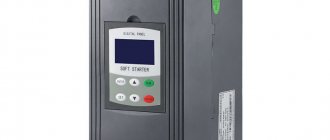
A reversing contactor, which is one of the types of electromagnetic starters. It ensures shaft rotation in both directions, maintains stable operation of motors, turns off power in a timely manner, and protects equipment in emergency situations.
From a device point of view, such contactors are an improved example of an electromagnetic starting device and are intended for direct operation with motors. Some models are equipped with additional devices that perform emergency shutdown in case of phase breaks and short circuits.
Features of reversing starters
Such connection diagrams are used in the designs of elevators, cranes, and drilling machines. If you don’t go into too much detail, it may seem that the motor switching circuit using reverse is more complicated. But in reality it turns out that there is nothing complicated - another power unit and control have been added to the design.
The cost of such devices is slightly higher due to the use of more elements. Essentially, these are two electromagnetic starters combined into one housing. The operating principle of the circuit is specific; you will need to carefully consider all the nuances.
Connecting a 220V motor to a single-phase network in reverse
In this case, it is possible to reverse the movement of the motor shaft if there is access to the terminals of its starting and operating windings. These motors have 4 outputs: two for the starting winding connected to the capacitor, two for the working one.
If there is no information about the purpose of the windings, it can be obtained by dialing. The resistance of the starting winding will always be greater than the working winding due to the smaller cross-section of the wire with which it is wound.
In a simplified version of the motor connection diagram, 220 V is supplied to the working winding, one end of the starting winding per phase or network zero (it makes no difference). The engine will begin to rotate in a certain direction. To get a reverse circuit, you need to disconnect the end of the starting winding from the contact and connect the other end of the same winding there.
To obtain a complete working circuit diagram, you need the following equipment:
- Safety circuit breaker.
- Push-button post.
- Electromagnetic contactors.
The reverse and forward circuit in this case is very similar to the connection circuit for a three-phase motor, but switching here occurs not of phases, but of the starting winding in one direction or the other.