To do this, use either a cardboard plug that comes with the shield, or a self-cut cover. Don't skimp on this product. The first step is to find out what kind of electrical system is in the house, then divide all points of electricity consumption into several categories.
After that, if there is such a need, make a niche for the shield, but if not, then simply drill holes for the fasteners and hang it on the wall. Electrical panel installation
If you have email. In a plastic or metal box, such busbars are installed in free space on insulating stands.
Electrical panel housing. The panel diagram is made for a three-wire electrical network.
De-energizes electrical wiring literally in milliseconds after detecting voltage leaks, for example, when the neutral wire is shorted to ground.
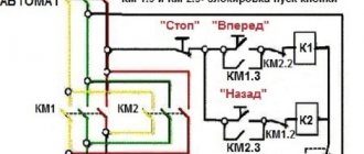
So, for your attention, a distribution board diagram for an apartment with an improved layout: With such a number of electricity consumers, there must be a three-phase network in and at the input, respectively, a three-pole circuit breaker of 63 Amperes. However, it is much more convenient when they are located one after another in the same sequence as in the diagram. The required holes are extruded along perforated lines.
How to assemble a shield for an apartment. Do-it-yourself electrical panel for an apartment. One of the options
Regulatory documents and rules
The requirements for installing an electrical panel are specified in GOST 51321.1-2007.
The panel is a switchgear operating under voltage up to 1 kW. Its features are discussed in Chap. 4.1. 7th edition of the PUE. The requirements for the ASU in a residential multi-storey building are specified in GOST 51732-2001, and for switchboards - in GOST R 51628-2000. Since the apartment electrical panel is a low-voltage switchgear and control device, you need to refer to GOST 51321.1-2007.
Basic requirements and installation rules
GOSTs and PUE indicate the correct way to connect the panel.
The standards note several points:
- the presence of a complete circuit with the rating of the circuit breaker, the type and cross-section of the cable, installed and one-time power, protection parameters of the housing shell;
- installation of modules equipped with a nameplate inside or outside is permitted;
- mandatory affixing of the “Caution Voltage” sign in the form regulated by GOST R 12.4.026;
- selection of cable cross-section for laying inside according to the rating of the circuit breakers;
- selection of wire insulation capable of withstanding an alternating current voltage of at least 660 V;
- protection of bolted connections from vibrations and short circuits with disc springs, controllers, spring washers, tips;
- assembly of neutral conductors on N and RE buses;
- connecting the REN wire to the RE panel;
- use of terminals to protect input and output wires;
- performing work using screwdrivers with slots for screw slots, tools with insulated handles;
- cable marking with colored PVC tubes - blue/light blue (working zero), yellow-green (protection zero), red/brown (phase);
- marking of N and RE bus contacts according to the serial numbers of protective circuit breakers;
- connection of one conductor per bus terminal N or RE;
- designation of outgoing cables with round (line voltage from 1000 V), square (voltage up to 1000 V), triangular (control) tags.
Buses N and RE, separated in the power cable, cannot be combined.
Which case is more reliable - metal or plastic?
Metal distribution panel in a wooden house
The apartment panel is available in metal and plastic casings. The choice of material depends on the project, design specifications and financial capabilities of the user.
The metal electrical panel has a number of features:
- reliable landing on protective zero;
- high anti-vandal characteristics;
- good fire resistance;
- installed on the street or in the entrance;
- moisture resistance class IP31 – IP54.
The disadvantage of a metal case is the need for grounding. The third wire will need to be brought out from the main power supply panel of the apartment.
Plastic electrical panel near the door in the hallway
The plastic case has the following characteristics:
- suitable for interior design;
- can be built into a special niche;
- resistance to wet environments;
- beautiful transparent or tinted door;
- excellent dust resistance.
If the insulation is poor, there is a risk that the plastic will ignite and cause a fire. In this case, it is better to purchase a box made of textolite.
Regardless of the housing material, you can choose a shield for installation in an apartment for 12-72 modules.
Principles of distribution of electricity by groups
Distribution boards, in which several machines are used for the entire apartment, are a thing of the past. The need for a large number of modular devices is explained by convenience and increased safety. If an outlet breaks down in one of the rooms, you can turn off one circuit breaker, and the rest of the network will continue to operate as normal. The basic rules for assigning groups are described below.
Reference! The rating of the machine directly depends on the cross-section of the cable, as well as the power of the consumers.
Electrical panel elements
The apartment panel consists of the following components:
- Circuit breaker. A two-row device is placed at the input and can de-energize the neutral and phase wires.
- RCD. It is a differentiated type relay. Necessary for quickly de-energizing the line when a voltage leak occurs.
- Additional auto switches that control the circuit with powerful appliances - electric stove, washing machine, water heater, air conditioner.
- Zero and ground buses. Copper strips with a dielectric base ensure the safety of the grounding contact and the working neutral.
- Frame. It contains all the nodes. It can be metal or plastic. Depending on the installation method, a distinction is made between wall-mounted and built-in models.
- DIN rail. A metal plate fixed to the body. Automatic machines are mounted to it with special fasteners.
- Connecting cables with a cross-section corresponding to the power rating of the equipment.
The outer box should not allow current to pass through, so it is better to buy models made of heat-resistant plastic or metal with a polymer coating.
What should be in the electrical panel
In a private house, the electric meter is installed on a pole.
The layout of the distribution board in an apartment or private house comes in several options. The main difference is the presence of a counter and a machine at the input. In private houses, meters are placed on a pole, and machines are placed on the wall. The meter can also be located inside the house, and then a shield is required.
In multi-apartment buildings, electrical boxes are installed on the staircase. In this case, a cabinet is required for RCDs and automatic machines. Installation inside an apartment is also allowed, but this requires a compact and roomy product.
Nuances of choosing modular equipment for an electrical panel
Electrical resistance of PUGV wires
Before installing an electrical panel in the apartment, you will need to make a diagram of it and coordinate it with the energy sales company. The drawing indicates each module and its purpose. When selecting devices, you need to consider the following points:
- Use of modules from the same manufacturer and series. Depending on the manufacturer, the width of the modules varies by several millimeters. The difference leads to inconsistency of parts.
- The cross-section of the PuGV installation wire is selected to match the cross-section of the input cable. Optimally – from 4 to 6 mm2.
- To mark zero, ground and phase, you will need a thermal tube of white, black, red (phase) and black (working zero) colors.
- Bus combs with one to three strips will provide connection of modular devices. The combs will also need end caps.
- Each group RCD will need a separate zero bus or cross-modules with good insulation.
- A DIN rail stop will prevent a number of modules from spreading to the sides.
- Plugs are used to close the formed cavities in the shield.
To secure the wires inside the shield, you should buy plastic clamps.
Assembling an electrical panel for a one-room apartment
Assembling the switchboard is not particularly difficult. Almost anyone can do this on their own if they have the desire to do it, know how to think and want to work with their hands. In continuation of a series of articles about organizing electrical wiring in a one-room apartment, I am publishing material with visual step-by-step photographs of assembling a simple switchboard. Here you will learn how to assemble a panel for an apartment with protection against overload, short-circuit currents and protection against accidental human contact with live parts. For this purpose, circuit breakers and RCDs will be used. I will tell you how to do all this without using additional special electrician tools, such as crimping pliers, etc. So, let's move on to the assembly.
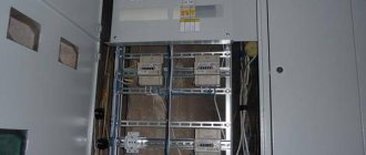
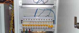
Here is the built-in cabinet itself for 18 modules of the Easy9 Box series from Schneider Electric.
In it we will install an introductory 2-pole circuit breaker, two RCDs and seven group circuit breakers.
I always do it this way. I install the introductory machine on the left, and then on the right I add other devices in turn. This is very convenient in understanding the diagram. First the input, then two group RCDs and at the end all the machines.
All modular devices are mounted on a standard DIN rail, which usually comes with the housing.
We planned to protect three lines with the first RCD, i.e. connect three circuit breakers to it. The second RCD is the remaining four lines. To do this, we take a single-phase comb busbar and cut it into the required sections. In our case, you can see the photo below. I would like to note that before sawing it is worth removing the dielectric protection (plastic casing) from the busbar.
Then we insert the combs into the machines and apply the tire body to them to determine its length. You can clearly see it in the photo below. You can cut off the tire body with a margin of 3-5 mm on both edges. Then you can do without side plugs.
It should turn out something like this.
Now we insert two small combs into the dielectric housing. If they are installed in place in the machines, then both cut tires will not contact each other. A distance between them of almost one centimeter is quite enough.
It should look like the photo below. Here one comb combines three circuit breakers, and the second connects the remaining four. Due to the solid dielectric housing, this is not visible, but everything is neatly closed.
Now we need to make jumpers from the input machine to the RCD. This is to supply “phase” and “zero” to the corresponding upper contacts of the protective devices. For these jumpers, you can buy 1 meter of VVNng 2x6 cable and cut it. The wires in it are round and rigid and therefore do not need to be crimped with tips. If you take a soft wire, for example PV3, then it will need to be crimped with pin lugs. To do this, you will have to buy special press pliers (crimpers). This is an additional expense of approximately one thousand rubles. Moreover, if you are not an electrician, you will no longer need them.
Below in the photo is an example of a phase jumper. Your curves may be different.
Let's put it in its place. This is to connect one lower contact of the input 2-pole circuit breaker with the upper phase contact of the first RCD. From the front it will look like the photo below.
Option for a simplified apartment panel diagram
A simple diagram of an apartment electrical panel.
You can independently assemble a small electrical panel and install it in the apartment. To avoid confusion, you should choose the simplest possible scheme. It must comply with the requirements of GOST 32395-2013.
It is advisable to use the diagram of an electrical apartment panel presented below for a one- or two-room apartment with a total cable length of 300-400 m. The work is carried out as follows:
- An input voltage switch with a current rating of 40 A or more is installed if the apartment has a single-phase load and has an electric stove.
- The wires are routed into groups, the brand and type of cable cross-section are indicated. For lighting, a 1.5 mm2 cable and a 10 A circuit breaker will be optimal; for sockets, a 2.5 mm2 wire and a 16 A device will be suitable.
- The bathroom can be connected to a difavtomat with a current leakage of 10 mA, combining consumers and lighting into one group.
- The hob and oven are powered as two different consumers.
- To protect against voltage fluctuations and equipment malfunctions, you can choose a voltage relay with the simplest connection system (phase + zero at the input and output).
The advantage of the scheme is the low cost of the components and the possibility of use in a small apartment. The downside of the disconnection is the lack of protection against current leakage in all groups, with the exception of the bathroom.
How to assemble an electrical distribution panel for an apartment
The process of assembling a switchboard requires special skills and knowledge. The service life of the devices and the reliability of the home’s power supply system depend on the correctness of the chosen scheme and the distribution of consumers. If in old houses with a minimum number of electrical appliances two or three automatic machines were enough, then in modern housing it is necessary to take care of the reliability of the network. Below are basic recommendations on how to assemble a switchboard for an apartment, what circuits and devices should be used, as well as recommendations for eliminating errors.
Scheme of a panel with an RCD for individual groups
Electrical panel diagram with RCD for individual groups
The RCD device is triggered at a load from 1 A to 80 mA, which prevents electric shock and death in cases of leakage. The device is suitable for residential premises where the electrical wiring has a total length of 400 m.
You can disable the apartment as follows:
- Installation of the device at the input. An RCD with a response limit of up to 30 mA is suitable for an apartment with a single-phase load of 11 kW.
- Protection against current leakage is also installed on the outlet lines and the split system group.
- One device is located on an integrated system, where each group has a circuit breaker.
- Installation of a standard circuit breaker with metal housings for lighting fixtures.
Each RCD must be placed on a separate bus.
What is an electrical panel and what is it for?
An electrical panel is a structure consisting of complex modular devices designed to control the power supply network. The main purposes include:
As a rule, they are mounted together with an electricity meter for greater convenience. In new housing stock, where metering devices are located in the corridor, shields are installed at the front door.
Important! It is necessary to provide free access to the panel in order to turn off the machines if necessary.
Assembly and connection algorithm
Regardless of which shield design is chosen, assembly activities are carried out sequentially. They are produced only in a clean and dry room.
Housing Installation
Mounting the housing in the wall
Wall-mounted models are placed on special fasteners, and built-in models are placed in a niche. Boxes can be assembled in a well-lit room near the exit. The humidity of the room should be 15%, the distance to the nearest ledge should be 15 cm, to the gas pipeline – from 1 to 1.5 m, from the floor – not lower than 1.4 m and not higher than 1.8 m.
Further instructions for assembling the built-in model include the following steps:
- Marking using the level of the area where the electrical panel will be located. A line is drawn along the edge of which the body is applied and outlined.
- Making cuts according to the drawing with a grinder. The disc should sink 1/2 into the wall.
- Using a chisel or hammer drill to make a niche along the thickness of the box.
- Checking the compliance of the body dimensions with the depth of the niche.
- Installing the standard mount on the body, marking the points for screwing in the screws.
- Drilling holes for fasteners with a hammer drill.
- Installation of DIN rail with modules.
- Filling cavities with polyurethane foam.
If the wall-mounted model does not come with fasteners, it can be nailed to the wall with dowels. To strengthen the fastening, the box sits on alabaster.
Proper cable management
An example of correct cable entry into the panel.
The cable organization is as follows:
- Removing the shield cover and making holes in it for a corrugated pipe with a diameter of 16 to 20 mm.
- Trimming the corrugated pipe before output.
- Removing the plug and connecting the input wire to the corresponding machine.
- Installing the cable on a bar with eyes, securing it with a plastic clamp. The screed is cut to the required length with wire cutters.
- Marking the wire with felt-tip pens.
- Laying the wire in a heat-shrinkable tube, designated by letters.
- Making notches on the plug for tight fixation in the holes.
- Place the plug in the installation location and secure it with screws.
Alabaster should be used to secure the input cable in the groove.
Wire cutting sequence
Removing insulation from a wire
To remove the insulation, use a special knife with a heel. Each core is marked after removing the insulating layer. Further actions:
- Splitting the wire from left to right at the top and right from the left corner at the bottom.
- Stripping the insulation from the end of the input cable.
- Wrap the wires 10 cm to the tip with masking tape.
- Cable marking.
It is necessary to leave a reserve length of the conductor 2 times larger than the segment from the box fastening to the entrance.
Ways to protect the internal filling of the shield
Insulating wires with electrical tape
Internal parts are the most expensive part of the system. To prevent dust and debris from getting into it, you can cover the ends of the wires with caps from pens, felt-tip pens or electrical tape. The moving elements are removed from the case, and the cables are located inside without sharp bends. The laying pattern is implemented in a clockwise or counterclockwise direction, from left to right. Bends are not allowed.
At the end of the work, you will need to close the box with a cardboard cover or the supplied lid and seal the gaps between the joints with paper tape.
Drawing up a diagram
Modern power supply systems involve the use of a three-wire cable, where one wire is a phase, and the rest are ground and zero. Given the growing power of devices, it is also necessary to divide them into groups, which allows to increase the service life of the wiring. Guided by these principles, we proceed to drawing up a diagram of the shield.
Advice! It is better to entrust the design of the panel and electrical wiring of the apartment to a professional so as not to miss important details. Otherwise, you will have to redo the repair.
It is mandatory to install a protection device on the input cable, which will protect the internal network from overvoltage. Then they install a voltage relay to control surges in the network, after which they proceed to the installation of groups and individual lines. It is worth noting that for powerful devices, in addition to switches, additional RCDs or differential circuit breakers are used. Such organization of the home electrical network is not only safe, but also convenient. If necessary, you can turn off the machine and turn off the washing machine. You can also turn off the RCD and de-energize all consumers included in the global group.
Connection to a three-phase network
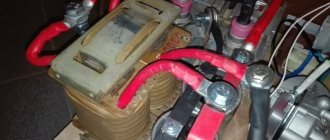
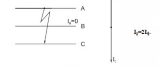
Three-phase 380V power is used in factories and small workshops. They power machine tools, various furnaces and asynchronous motors (elevators). Installing an RCD in a three-phase network is no fundamentally different from a single-phase one. The difference lies only in the number of pins on the protective device. The three-pole RCD has 8 contacts for connecting cables. Four incoming L1, L2, L3 and N and 4 outgoing with similar markings.
Three-pole RCD
When connecting, there may be confusion in the wires. To understand the color and letter markings, it is enough to know the simple relationships from the table.
| Russian designations | European designations | ||
| Phase A | Yellow | L1 | Brown |
| Phase B | Green | L2 | Black |
| Phase C | Red | L3 | Grey |
| Neutral wire | Blue (cyan) | N | Blue (cyan) |
| Ground wire | P.E. | Green-yellow | |
Introductory three-phase RCD + separate group
The device is installed after the introductory three-pole circuit breaker. Three power supply conductors pass through it. Then they go directly to the RCD. Connection is carried out taking into account the markings. Terminal L1 at the output of the machine is connected to L1 on the protective device, L2 to L2, and so on.
After the introductory three-phase RCD, the wires go to the group circuit breakers. The zero core is connected to the common N bus. Ideally it is blue. Then the phase wires from the machines are connected to single-pole group RCDs and distributed to consumers.
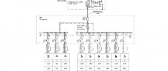
Input protective device + three-phase meter
The scheme is similar to the previous one. However, in this case a three-phase electricity meter is added. It has 8 pins designed to connect 3 phases and zero. The metering device is mounted at the output of the input machine. After the meter there is a three-phase RCD. Behind it are group single-pole circuit breakers and residual current devices.
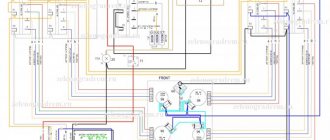
Option 5
The fifth option presents a diagram of a three-phase shield without an incoming RCD, but using single-phase automatic circuit breakers for some consumers. RCBOs are placed one per group and therefore their number can be equal to the number of groups. This way all consumer groups will be independent of each other. That is, if a current leak occurs in one device, only the circuit breaker to which it is connected will turn off. When using an RCD with 3-5 circuit breakers, when the RCD is triggered, 3-5 groups will be switched off, respectively. And this is no longer very convenient for the exploitation of consumers.
The above diagrams have a visual appearance in order to convey the very essence of connecting different protective devices into one general electrical panel diagram. Also, these examples are very basic and therefore your circuits will be much larger and more complex.
Purpose and operating principle of RCD in pictures
The residual current device is a current protection device and ranks second after the circuit breaker in terms of safety. It has already saved the health of many people and prevented electrical injuries.
The need to use RCDs has been confirmed by the requirements of the time and is dictated by electrical safety rules.
How does protective shutdown work when a leakage current occurs?
The phase comparison body controls the magnitude of the vectors of incoming and outgoing currents along the phase and zero potential conductors, constantly comparing their magnetic fluxes.
If the value of the second vector has decreased more than the permissible set value, then a conclusion is drawn that a malfunction has occurred. The power contacts are automatically disconnected from the resulting leakage current.
The RCD prevents the passage of current through the human body in case of accidental contact with exposed live parts or damage to the wiring insulation, when a dangerous potential appears on the body of an electrical device.
Additional purpose of the device: preventing a building fire due to a violation of the dielectric properties of the insulation, creating random paths of emergency currents.
The differential element operates in all building grounding systems. However, the most correct and safe situation is created in the TN-S and TN-CS , TT with an additional PE grounding line.
Buildings with the old TN-C roughen the sensitivity of the reference organ.
RCD electrical circuits: 2 options for apartments and houses
The protection is produced in ready-made modules for installation on a Din rail with the possibility of installation in single-phase or three-phase wiring.
Connection diagram for single-phase RCD
The 220 volt network includes a module with two current lines with phase and zero potentials.
A diagram of the internal design of the protection is printed directly on the case and is given in the documentation. The incoming phase wire is connected from above to terminal No. 1, and from terminal No. 2 it goes to consumers.
The zero potential is applied to the upper terminal N and removed from the lower one. These connection rules cannot be changed: otherwise the phase comparison organ will not be able to work correctly and false alarms will occur.
Connection diagram for three-phase RCD
Three input phase conductors are mounted alternately to the upper terminals No. 1, 2 and 3. From the bottom of the module from terminals No. 2, 4 and 6 they are removed and sent to the consumer. The zero potential is connected from above to the “N” terminal and removed from the bottom.
Various manufacturers constructively place the working zero line to the right or left of the phase lines. All these variations are shown in a picture diagram on the protection housing.
It is permissible to swap phase lines with each other, but they should not be confused with the zero current line. The winding of the “Test” check button is connected to it. When pressed, the protection will not work correctly.
How to calculate the number of places in an electrical panel?
All equipment for the switchboard is standardized and installed on a special DIN rail. The unit of measurement for space is considered to be a “module” with a width of 17.5 mm. All panels are sold depending on the amount of space: for 8, 12, 24, 36 modules.
Reference! To calculate the number of seats, it is necessary to take into account all devices, including RCDs, automatic machines, voltage relays, and differential automatic devices.
Circuit breakers have a standard width of 17.5 mm. The remaining devices have the following characteristics: