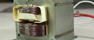
General information about voltage multipliers
The essence of the multiplier is to convert the alternating voltage received from a low-voltage source into a high direct current voltage.
There are different options for these devices, such as a Schenkel voltage multiplier and other circuits designed for specific equipment. In electronics, voltage multipliers are special circuits that convert the incoming voltage level upward. At the same time, these devices also perform a straightening function. Multipliers are used in cases where it is undesirable to use an additional step-up transformer in the overall circuit due to the complexity of its design and large size. In some cases, transformers cannot raise the voltage to the required level because a breakdown may occur between the turns of the secondary winding. These features should be taken into account when solving the problem of how to make various options for doublers with your own hands.
Multiplier circuits typically use the properties and characteristics of single-phase, half-wave rectifiers driving a capacitive load. During the operation of these devices, a voltage is created between certain points with a value exceeding the value of the input voltage. The terminals of the diode included in the rectifier circuit act as such points. When you connect another identical rectifier to them, you get an asymmetrical voltage doubler circuit.
Thus, each voltage multiplier as a boosting device can be symmetrical or asymmetrical. In addition, they are all divided into categories of the first and second kind. A symmetrical multiplier circuit consists of two asymmetrical circuits connected to each other. One of them changes the polarity of the capacitors and the conductivity of the diodes. Symmetrical multipliers have better electrical characteristics; in particular, the rectified voltage has double the ripple frequency.
Various types of such devices are widely used in electronic equipment and equipment. With the help of these devices, it became possible to carry out multiplication and obtain voltages of tens and hundreds of thousands of volts. The voltage multipliers themselves are lightweight, small in size, and easy to manufacture and further operate.
Pulse type inverting converter
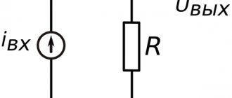
A pulse-type inverting converter contains the same combination of basic elements, but again in a different connection (Fig. 3): a series chain of switching element S1, diode VD1 and load resistance RH with filter capacitor C1 is connected to the power source.
Inductive energy storage L1 is connected between the connection point of the switching element S1 with the diode VD1 and the common bus.
Rice. 3. Pulse voltage conversion with inversion.
The converter works like this: when the key is closed, energy is stored in an inductive storage device. Diode VD1 is closed and does not pass current from the power source to the load. When the switch is turned off, the self-inductive emf of the energy storage device is applied to a rectifier containing diode VD1, load resistance Rн and filter capacitor C1.
Since the rectifier diode passes only negative voltage pulses into the load, a voltage of a negative sign is formed at the output of the device (inverse, opposite in sign to the supply voltage).
Principle of operation
In order to imagine how a voltage multiplier works, we consider the simplest circuit of a half-wave device shown in the figure. When the negative half-cycle of the voltage begins to operate, diode D1 opens and capacitor C1 is charged through it. The charge must be equal to the amplitude value of the applied voltage.
When a period with a positive wave occurs, the next capacitor C2 is charged through diode D2. In this case, the charge acquires a high double value compared to the applied voltage. Next comes a negative half-cycle, during which capacitor C3 is charged to double the value. In the same way, during a further half-cycle change, capacitor C4 is charged, again with double the value.
In order to start the device, complete voltage periods of several cycles are required, creating voltages on the diodes. The voltage value obtained at the output consists of the sum of the voltages of capacitors C2 and C4, connected in series and constantly charged. Ultimately, an output alternating voltage is generated that is 4 times higher than the input voltage. This is the principle of operation of a voltage multiplier.
The very first capacitor C1, fully charged, has a constant voltage value. That is, it performs the function of a constant component Ua used in calculations. Consequently, it is possible to further increase the potential of the multiplier by connecting additional links made according to the same principle, since the voltage on the diodes in each of these links will be equal to the sum of the input voltage and the constant component. Due to this, any multiplication coefficient with the required value is obtained. The voltage on all capacitors except the first one will be equal to 2x Ua.
We recommend reading: How to check a battery with a multimeter: for performance
If the multiplier uses an odd factor, capacitors located at the top of the circuit are used to connect the load. If it is even, on the contrary, the lower capacitors are used.
Direct connection of the diode. Direct current.
If you connect a constant voltage source to the diode electrodes: to the anode terminal “ plus
" and the cathode terminal is "
minus
", then the diode will be in
the open
state and a current will flow through it, the magnitude of which will depend on the applied voltage and the properties of the diode.
With this polarity of connection, electrons from the region n
-type electrons will move towards the holes into the
p
-type region, and holes from the
p
-type region will move towards the electrons into the
n
-type region.
At the interface between the regions, called an electron-hole or pn junction , they will meet, where their mutual absorption or recombination
.
For example. Major charge carriers in the n
-type electrons, overcoming
the p-n
junction, enter the
p
-type hole region, in which they become
minority
.
Having become minority electrons, they will be absorbed by majority
carriers in the hole region -
holes
.
In the same way, holes entering the n
-type electronic region become
minority
charge carriers in this region, and will also be absorbed by
the majority
carriers -
electrons
.
Diode pin connected to negative
The pole of a constant voltage source will
give up
n
region , replenishing the decrease in electrons in this region.
And the contact connected to the positive
pole of the voltage source is able
to accept
the same number of electrons
from the
p p
-type region is restored.
Thus, the conductivity the p-n
junction will become
large
and the current resistance will be
small
, which means that a current will flow through the diode, called
diode current Ipr
.
Where is the device used?
Multipliers have found their application in different types of devices, these are: laser pumping systems, X-ray wave radiation devices in their high voltage units, for illuminating displays of liquid crystal structure, ion pumps, traveling wave lamps, air ionizers, electrostatic systems, particle accelerators, copiers, televisions and oscilloscopes with picture tubes, as well as where high direct electricity of low current is required.
Converter with master oscillator-multivibrator
To obtain an output voltage of 30...80 V, P. Belyatsky used a converter with a master oscillator based on an asymmetrical multivibrator with an output stage loaded on an inductive energy storage device - inductor (choke) L1 (Fig. 7).
Rice. 7. Circuit of a voltage converter with a master oscillator based on an asymmetrical multivibrator.
The device is operational in the supply voltage range of 1.0. ..1.5 V and has an efficiency of up to 75%. In the circuit, you can use a standard inductor DM-0.4-125 or another with an inductance of 120...200 μH.
An embodiment of the output stage of the voltage converter is shown in Fig. 8. When a 7777-level (5 V) rectangular control signal cascade is applied to the input of the cascade, the output of the converter, when powered from a 12 V produces a voltage of 250 V at a load current 3...5 mA (load resistance is about 100 kOhm). Inductance of inductor L1 is 1 mH.
As VT1, you can use a domestic transistor, for example, KT604, KT605, KT704B, KT940A(B), KT969A, etc.
Rice. 8. Option for the output stage of the voltage converter.
Rice. 9. Diagram of the output stage of the voltage converter.
A similar circuit of the output stage (Fig. 9) made it possible, when powered from a source with a voltage of 28V and a current consumption of 60 mA to obtain an output voltage of 250 V at a load current of 5 mA . The inductance of the inductor is 600 μH. The frequency of control pulses is 1 kHz.
Depending on the quality of the inductor, the output voltage can be 150...450 V with a power of about 1 W and an efficiency of up to 75%.
Voltage multiplier on diodes and capacitors
In the manufacture of electronic devices, in particular power supplies, in some cases it becomes necessary to have a higher rectified voltage than at the terminals of the secondary winding of the transformer or in a 220 V socket.
For example, after rectifying the mains voltage of 220 V on the filter capacitor at a very light load, you can obtain a maximum amplitude value of the alternating voltage of 311 V. Consequently, the capacitor will be charged to the specified value.
However, using a voltage multiplier you can increase it to 1000 V or more.
Half-wave multiplier
Figure 1 shows the circuit of a half-wave sequential multiplier.
During the negative half-cycle of the voltage, the capacitor is charged through the diode, which is open. The capacitor is charged to the amplitude value of the applied voltage. During the positive half-cycle, the capacitor is charged through the diode to a potential difference. Then, during the negative half-cycle, the capacitor is charged through the diode to a potential difference. During the next positive half-cycle, the capacitor is charged to voltage. In this case, the multiplier is started over several periods of voltage change. The output voltage is constant and it is the sum of the voltages on the capacitors and , which are constantly charging, that is, it is a value equal to .
The reverse voltage on the diodes and the operating voltage of the capacitors in such a multiplier are equal to the full amplitude of the input voltage
When implementing a multiplier in practice, attention should be paid to the insulation of the elements in order to prevent a corona discharge, which can damage the device. If it is necessary to change the polarity of the output voltage, then change the polarity of the diodes when connecting
Series multipliers are used especially often, since they are universal and have uniform voltage distribution across diodes and capacitors. With their help, you can implement a large number of multiplication stages.
Parallel voltage multipliers are also used. They require a smaller capacitor capacity per multiplication stage. But their disadvantage is considered to be an increase in the voltage on the capacitors with an increase in the number of multiplication stages, which creates a limitation in their use to an output voltage of about 20 kV. In Fig. Figure 2 shows a diagram of a half-wave parallel voltage multiplier.
In order to calculate the multiplier, you need to know the basic parameters: input AC voltage, output voltage and power, required dimensions (or size restrictions), conditions under which the multiplier will operate. It should be taken into account that the input voltage must be less than 15 kV, frequency from 5 to 100 kHz, output voltage less than 150 kV. The temperature range is usually -55. Typically, the multiplier power is up to 50 W, but more than 200 W are also found.
For a series multiplier, if the frequency at the input to the multiplier is constant, then the output voltage is calculated using the formula:
where is the input voltage; – input voltage frequency; N – number of multiplication stages; C – stage capacitor capacity; I – load current strength.
Multiple voltage multiplier
The processes in the voltage tripling circuit occur in the following sequence: first, capacitors C1 and C3 are charged through resistance R and the corresponding diodes VD1 and VD3. In the next half-cycle, C2 is charged through VD2 to double the voltage (C1 + winding) and triple the value is obtained at the load resistance.
We recommend reading: Starter (contactor) connection diagram: how to do it yourself
Of greater interest is the following voltage multiplier. Let's consider the principle of its operation. When the potential of point 1 is positive relative to point 2, current flows along the path through VD1 and C1, charging the capacitor.
In the next half-cycle, when the current has changed its direction, the second capacitor is charged through the second diode to a value equal to the sum of the voltages on C1 and the transformer winding. In this case, C1 will be discharged. In the third half-cycle, when the first capacitor begins to charge again, C2 will discharge through the third diode onto C3, charging it to double the value relative to the winding terminals.
By the end of the third half-cycle, the total voltage of the charged capacitors C1 and C3 will be applied to the load, i.e. approximately triple the value.
By analogy with the considered circuits, circuits with a higher multiplication factor can be constructed. But it should be remembered that with an increase in the number of multiplications, due to the greater content of diodes and capacitors in the circuit, the internal resistance of the rectifier increases, which leads to an additional voltage drop.
Voltage multiplying circuits are used to power small loads, i.e. The load resistance must be high. Otherwise, you need to use high-capacity non-polar capacitors designed for high voltage. This is due to the fact that with a significant load current, the capacitors will quickly discharge, which will cause unacceptably large ripples on the load.
Pumping capacitors in a multiplier
In other words, in the device of the constant voltage multiplier there is a certain transient process of establishing the output parameter corresponding to the declared one. The easiest way to see this is with the doubling of electricity. When capacitor C1 is charged to its full value through semiconductor D1, then in the next half-wave it, together with the source of electricity, simultaneously charges the second capacitor. C1 does not have time to completely give up its charge to C2, so at first there is no double potential difference at the output.
At the third half-wave, the first capacitor is recharged and then applies potential to C2. But the voltage on the second capacitor is already in the opposite direction to the first. Therefore, the output capacitor is not fully recharged. With each new cycle, the electricity at element C1 will tend to the input voltage, and the voltage at C2 will tend to double its value.
How to calculate the multiplier
When calculating a multiplying device, it is necessary to start from the initial data, which are: the current required for the load (In), the output voltage (Uout), and the ripple factor (Kp). The minimum value of the capacitance of capacitor elements, expressed in μF, is determined by the formula: C(n)=2.85*n*In/(Kp*Uout), where:
- n is the number by how many times the input electricity increases;
- In – current flowing in the load (mA);
- Kp – pulsation coefficient (%);
- Uout is the voltage received at the device output (V).
By increasing the capacitance obtained by calculations by two or three times, the value of the capacitance of the capacitor at the input of circuit C1 is obtained. This element rating allows you to immediately receive the full voltage value at the output, rather than wait until a certain number of periods have passed. When the load operation does not depend on the rate of increase of electricity to the nominal output, the capacitance of the capacitor can be taken identical to the calculated values.
It is best for the load if the ripple factor of the voltage multiplier on the diodes does not exceed 0.1%. The presence of pulsations up to 3% is also satisfactory. All diodes of the circuit are selected so that they can easily withstand a current strength twice its value in the load. The formula for calculating the device with great accuracy looks like this: n*Uin - (In*(n3 + 9*n2/4 + n/2)/(12 *f* C))=Uout, where:
- f – voltage frequency at the device input (Hz);
- C – capacitor capacitance (F).
Lighting engineering
An example of using a voltage multiplier by four [1] is the circuit for starterless starting of a daytime running light (LDS), shown in Fig. 5, which consists of two voltage doublers connected in series for direct current and in parallel for alternating current.
Rice. 5. Circuit of a voltage multiplier by four for starterless starting of a daytime running lamp.
The lamp lights up without heating the electrodes. Breakdown of the ionized gap of the “cold” LDS occurs when the ignition voltage of the LDS is reached at the output of the UN. The ignition of the LDS occurs almost instantly.
A lit lamp shunts, with its low input resistance, the high output resistance of the UN, the capacitors of which, due to their small size, cease to function as sources of increased voltage, and the diodes begin to work as ordinary valves.
The 2-winding inductor L1 (or two 1-winding inductors) is used to smooth out the ripples of the rectified voltage. The voltage drop of the supply network is approximately evenly distributed across the ballast capacitors C1, C2 and LDS, which are connected in series with alternating current, which corresponds to the normal operating mode of the LDS.
When used in this circuit, LDS with a cylindrical part diameter of 36 mm ignite without any problems; LDS with a diameter of 26 mm ignite worse, since due to the peculiarities of their design, the ignition voltage of even new lamps without filament heating can exceed 1200 V.
Approximate calculation of the multiplier circuit
Before starting the calculation, the main characteristics of the device are set. This is especially important when you need to make a voltage multiplier yourself. First of all, these are the input and output voltage values, power and overall dimensions. Some restrictions regarding voltage parameters should also be taken into account. Its input value should be no more than 15 kV, the frequency range ranges from 5 to 100 kHz.
The recommended value of the output high voltage voltage is not higher than 150 kV. The output power of the voltage multiplier is within 50 W, although it is possible to create a device with higher parameters, in which the power reaches even 200 W.
The output voltage is directly dependent on the current loads and can be calculated using the formula: Uout = N x Uin – (I (N3 + +9N2 /4 + N/2)) / 12FC, in which N corresponds to the number of stages, I – current load, F – input voltage frequency, C – generator capacity. If you set the required parameters in advance, this formula will help you easily calculate what capacity the capacitors used in the circuit should have.
We recommend reading: Voltage rectifier: operating principle and types
Boost switching converter
The step-up pulse voltage converter (Fig. 2) is made on the same basic elements, but has a different combination: a series chain of inductive energy storage L1, diode VD1 and load resistance RH with a filter capacitor C1 connected in parallel is connected to the power source. The switching element S1 is connected between the connection point of the energy storage device L1 with the diode VD1 and the common bus.
Rice. 2. Operating principle of a boost voltage converter.
When the switch is open, current from the power source flows through the inductor, which stores energy. Diode VD1 is closed, the load circuit is disconnected from the power source, key and energy storage device.
The voltage across the load resistance is maintained thanks to the energy stored on the filter capacitor. When the switch is opened, the self-induction EMF is summed with the supply voltage, the stored energy is transferred to the load through the open diode VD1. The output voltage obtained in this way exceeds the supply voltage.
Voltage multiplier rectifier circuits
It is advisable to use circuits with voltage multiplication to obtain sufficiently high rectified voltages at low load currents. These circuits are used to power cathode ray tubes, photomultipliers, and in installations for testing electrical strength.
Voltage multiplying rectifier circuits contain several rectifiers with a capacitive filter, the output voltages of which are summed.
Single-phase single-phase voltage doubling circuit
The circuit in Fig. 5 represents two single-phase half-wave rectifiers. The first rectifier VD1, C1 is a half-wave rectifier with a diode connected in parallel. Due to its operation, capacitor C1 is charged to the amplitude voltage U2. A constant voltage UC1=U2m is formed on it. A pulsating voltage is generated on diode VD1. The maximum voltage value on it
UVD1,MAX=UC1+U2m .
This pulsating voltage is finally rectified and smoothed by a conventional rectifier with a capacitive load VD2, C2. As a result, we obtain an output voltage U0 approximately equal to twice the voltage amplitude of the secondary winding of the transformer.
The ripple frequency of the rectified voltage at the load is equal to the network frequency.
The reverse voltage on the diodes is equal to twice the voltage amplitude of the secondary winding of the transformer.
The main disadvantage of the circuit is that the main ripple frequency of the rectified voltage is equal to the network frequency.
To increase the ratio of the rectified voltage, increase the number of diodes and capacitors, including them in a similar way to the described circuit. In Fig. 6, a shows a voltage multiplication circuit, where, in order to obtain different voltage multipliers, appropriate options for connecting the load to the circuit are provided (shown in dotted lines), namely: by connecting the load to points b, c and d of the circuit, we obtain a voltage multiplication of 2, 3, respectively and 4 times. In this circuit, all capacitors with odd numbers (C1, C3) are charged in one half-cycle of voltage U2, and with even numbers (C2, C4) - in another half-cycle.
The higher the voltage multiplication factor, the greater the rectified voltage ripple will be with the same capacitance of the capacitors, since they are connected in series for the charging and discharging currents.
The disadvantages of such rectifiers are similar to those of a half-wave, single-phase rectifier with a capacitive load. In addition, they have increased internal resistance due to the series connection of diodes.
Two-phase symmetrical circuits
Two-phase symmetrical multiplication circuits are possible; obtained by connecting several asymmetrical circuits.
Capacitors with odd numbers (C1, C3, C5, C1', C3', C5') are charged by the currents of the corresponding diodes once during the period of voltage of the secondary winding, capacitors with even numbers (C2, C4, C6) - twice, so the pulsation frequency of the rectified voltage is 2 times the network frequency.
Principles of construction and operation of voltage multiplication circuits.
Recently, radio amateurs are increasingly interested in power supply circuits built on the principle of voltage multiplication. There are many reasons for this, some of the most important being the appearance on the market of small-sized high-capacity capacitors and the sharp rise in price of copper wire used in winding transformers. It is also important that voltage multiplication circuits can significantly reduce the weight and dimensions of the equipment. However, many attempts by radio amateurs to select such schemes end in failure, since several essential conditions for sufficiently reliable and high-quality operation of such seemingly simple schemes are not met. In order to understand how to choose the right circuit and multiplier elements, let's consider the operating principles of such devices.
Voltage multiplier circuits are divided into symmetrical and asymmetrical. First, let's look at the principle of operation and construction of asymmetric circuits. Single-ended multiplier circuits are divided into two types: Type I multiplier circuits and Type II multiplier circuits.
Multiplication scheme of the first kind
presented in the figure.
During the half-cycle of the voltage, when at point “A” there is a negative potential relative to point “F”, capacitor C1 will be charged along the circuit “F” -VD1 – “B” - C1 – “A” to the amplitude voltage value at the input of the circuit (at points “ A” – “F”). Simultaneously with the charge C1, capacitor C3 will also be charged along the circuit “F” – VD1 – “B” – VD2 – “C” – VD3 – “D” – C3 – “A” also to the amplitude value of the voltage at the input of the circuit. Other capacitors of the multiplication circuit will also be charged, which may be connected with one terminal to point “A”. Let us pay attention to the fact that all these capacitors are charged through a chain of series-connected diodes. Through the diode VD1 flows the charging current of the capacitors of all multiplication stages, through the diodes VD2, VD3 and further - the charging current of all other capacitors connected by one terminal to point “A”, except the first. Thus, significant capacitor charging currents initially pass through the diodes. This must be taken into account when choosing elements for the multiplication circuit. Capacitors C2 and all that may be in other stages and are connected with one terminal to point “F” are not charged during this half-cycle, since they turn out to be shunted by pairs of diodes VD1-VD2, VD3-VD4 and then VD(N)-VD(N+1) .
With the beginning of another half-cycle, the positive potential will be at point “A”. Since capacitor C1 is already charged to the same potential as the maximum Uo, it will be connected in series with the power source and will be discharged along the circuit “B” - VD2 - “C” - C2 - “F” - Source - “A”. Since capacitor C2 was discharged, it will now charge to almost double the amplitude voltage Uo. “Almost” because C1 will give up part of its charge to capacitor C2 during this short period of time.
If the capacitance of capacitor C1 is much greater than the capacitance of capacitor C2, then C2 will charge to twice the amplitude value of the voltage Uo. If the capacitances of these capacitors are equal, then all the same, after several periods the voltage on capacitor C2 will reach double Uo. Similarly, along the circuit “D” – VD(N) – “E” – C(N) – “F” – Source – “A” the capacitor C(N) will be charged to double the voltage Uo.
In the next half-cycle of voltage, capacitor C2, charged to twice the voltage Uo, will be connected in series and along the circuit “C” - VD3 - “D” - C3 - “A” - Source - “F” will charge capacitor C3 to almost triple the voltage Uo. And capacitor C1 will be recharged to voltage Uo.
In the next half-cycle, capacitor C2 will be charged in the same way as already described, to double the voltage, and capacitor C(N) will be charged along the circuit D – VD(N) – E – C(N) – F – Source – A – C3. Moreover, due to triple the voltage on capacitor C3 and the voltage at the input, capacitor C(N) will be charged to quadruple Uo. If you increase the multiplication stages further, their work will be no different from the work of the first multiplication stages. It should be noted that in one half-cycle the capacitors connected by one terminal to point “A” will be charged, and in the other - the capacitors connected by one terminal to point “F”, therefore the ripple frequency at the output of the first-kind multiplication circuit is equal to the frequency of the supply voltage.
The minimum permissible value of the capacitor at the output of the multiplication circuit C(N) can be calculated based on the given level of rectified voltage ripple. First, let's determine the load resistance:
Rn (Com) = Uout (V) / In (mA)
To power the anode circuit of the power amplifier on 3 GU-50, we set: the voltage at the output of the multiplier is 1200 Volts at a current of 400 mA.
Substituting the data into the formula, we obtain the rectifier load resistance Rн = 3 Kom.
(Further, all practical calculations will be made specifically for this type of amplifier.)
Now let's determine the capacitance of the capacitor at the output of the multiplication circuit.
С(n) = 5.7 / Kп* Rн (μF)
For power amplifiers of HF radio stations operating in telegraph mode, the ripple factor is selected in the range of 0.5 - 3.0% For transmitters operating in SSB, the ripple factor should be significantly lower. Let's choose Kp = 0.1%, then: C(n) = 19 μF (choose 20 μF)
In order to obtain the flattest possible static characteristic, it is important to maintain certain proportions in the capacitances of the capacitors, which will ensure equality of the energies accumulated by each capacitor when operating on a real load. The best results are obtained by a number of containers for which:
С(N) = M * С(n)
Where: C(N) is the capacitance of a specific capacitor, C(n) is the capacitance of the capacitor at the output of the circuit, M is the capacitance increase factor determined from the table:
| Capacitor number according to the diagram | Voltage multiplier | Specific rating for an amplifier with 3 GU-50 lamps at Uout = 1200V Iout = 0.4A | |||
| 5 | 4 | 3 | 2 | ||
| C1 | 25 | 16 | 9 | 4 | 320 X 300 V |
| C2 | 6,25 | 4 | 2,25 | 1 | 80 X 600 V |
| C3 | 2,78 | 1,78 | 1 | — | 35.6 X 900 V |
| C4 | 1,56 | 1 | — | — | 20 X 1200 V |
| C5 | 1 | — | — | — | — |
Asymmetrical multiplication scheme of the second kind.
The operating principle of this multiplier is similar to the operation of a multiplier of the first kind.
The main difference is that in this circuit all capacitors except C1 are charged only to twice the voltage Uo. Capacitor C1 is charged only to Uo. Thus, the operating voltage of capacitors and diodes in a voltage multiplier of the second kind can be significantly lower than in a multiplier of the first kind. The “starting” current through the diodes in this circuit is also less, since it is determined by the capacitance of only one capacitor C1. Diodes can be selected with current
Ipr. = 2.1 * In = 2.1 * 0.4 = 0.82 A
The required capacitance of the capacitors in this circuit is determined by the formula:
C (μF) = 2.85 * N / Kp*Rn = 2.85 * 4 / 3 * 0.1 = 38 μF
Despite the doubling of each capacitance, the total capacitance of the capacitors in such a circuit will be less, with the same ripple. It is only necessary to increase the capacitance of capacitor C1 by 4 times compared to the others. Although in most cases a two to threefold increase in the capacitance of capacitor C1 is sufficient.
About turning on the load in such a circuit: With an even number of multiplication stages (for example, 2,4,6,8, etc.), the voltage to the load is removed from the capacitors with even numbers (points “C”, “E”, etc.) If it is necessary to obtain an odd number of multiplication stages (3,5,7, etc.), the load is connected to capacitors with odd numbers (points “A”, “D”, etc.
Symmetrical voltage multiplier circuits.
A symmetrical voltage multiplication circuit is obtained by using two asymmetrical circuits, one of which requires changing the polarity of the electrolytic capacitors and changing the conductivity of the diodes.
Symmetrical circuits have the same properties, but better performance. An important advantage of symmetrical circuits is the doubled ripple frequency of the rectified voltage.
Practical voltage multiplier circuits:
The circuits are the most common, on the left is a symmetric doubler circuit, on the right is an asymmetric doubler circuit. As you can see, this doubling pattern can be attributed to both the 1st kind and the 2nd kind at the same time.
Below is a circuit for multiplying the voltage of the first kind, at the top is a circuit for multiplying the second kind. Circuits with odd multipliers cannot be completely symmetrical.
On the left (above and below) are the multiplication schemes of the first kind, on the upper right is the multiplication scheme of the second kind. Bottom right is a circuit of a symmetrical multiplier by 4.
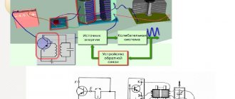
Voltage converter with inductive energy storage
A voltage converter with an inductive energy storage, which allows maintaining a stable regulated voltage at the output, is shown in Fig. 13.
Rice. 13. Voltage converter circuit with stabilization.
The circuit contains a pulse generator, a two-stage power amplifier, an inductive energy storage device, a rectifier, a filter, and an output voltage stabilization circuit. Resistor R6 sets the required output voltage in the range from 30 to 200 V.
Transistor analogues: VS237V - KT342A, KT3102; VS307V - KT3107I, BF459 - KT940A.
Voltage converter based on KR1006VI1
A voltage converter based on a pulse generator based on a DA1 KR1006VI1 microcircuit, an amplifier based on a field-effect transistor VT1 and an inductive energy storage device with a rectifier and filter is shown in Fig. 10.
At the output of the converter, with a supply voltage of 9V and a current consumption of 80...90 mA, of 400...425 V is generated . It should be noted that the value of the output voltage is not guaranteed - it significantly depends on the design of the inductor (choke) L1.
Rice. 10. Circuit of a voltage converter with a pulse generator on the KR1006VI1 microcircuit.
To obtain the desired voltage, the easiest way is to experimentally select an inductor to achieve the required voltage or use a voltage multiplier.
Pulse-resonant converter
Pulse-resonant converters designed by the so-called. N. M. Muzychenko, one of which is shown in Fig. 4.27, depending on the shape of the current in the VT1 switch, they are divided into three types, in which the switching elements close at zero current and open at zero voltage. At the switching stage, the converters operate as resonant converters, and the rest, most of the period, as pulse converters.
Rice. 27. Scheme of a pulse-resonance converter N. M. Muzychenko.
A distinctive feature of such converters is that their power part is made in the form of an inductive-capacitive bridge with a switch in one diagonal and with a switch and power supply in the other. Such schemes (Fig. 27) are highly efficient.
Source: Shustov M. A. Practical circuitry. Voltage converters.
Buck and invert voltage converters
Two options - step-down and inverting voltage converters [4.1] are shown in Fig. 14. The first of them provides an output voltage of 8.4 V at a load current of up to 300 mA , the second allows you to obtain a voltage of negative polarity ( -19.4 V ) at the same load current. The output transistor VTZ must be installed on the radiator.
Rice. 14. Circuits of stabilized voltage converters.
Transistor analogues: 2N2222 - KTZ117A 2N4903 - KT814.
Voltage converter with pulse energy storage
In the S. F. Sikolenko voltage converter with “pulse energy storage” (Fig. 26), switches K1 and K2 are made on KT630 transistors, the control system (CS) is on a K564 series microcircuit.
Rice. 26. Circuit of a voltage converter with pulse accumulation.
Storage capacitor C1 - 47 µF. A 9 V battery is used as a power source. The output voltage at a load resistance of 1 kOhm reaches 50 V. The efficiency is 80% and increases to 95% when using CMOS structures such as RFLIN20L as key elements K1 and K2.
Inverters on specialized chips
It is most convenient to assemble highly efficient modern voltage converters using microcircuits specially created for these purposes.
KR1156EU5 microcircuit (MC33063A, MC34063A from Motorola) is designed to operate in stabilized step-up, step-down, and inverting converters with a power of several watts.
In Fig. Figure 17 shows a diagram of a step-up voltage converter based on the KR1156EU5 microcircuit. The converter contains input and output filter capacitors C1, SZ, C4, storage choke L1, rectifier diode VD1, capacitor C2, which sets the operating frequency of the converter, filter choke L2 for smoothing ripples. Resistor R1 serves as a current sensor. The voltage divider R2, R3 determines the output voltage.
Rice. 17. Circuit of a step-up voltage converter on the KR1156EU5 microcircuit.
The operating frequency of the converter is close to 15 kHz at an input voltage of 12 V and rated load. The range of voltage ripples on capacitors SZ and C4 was 70 and 15 mV, respectively.
Inductor L1 with an inductance of 170 μH is wound on three glued rings K12x8x3 M4000NM with PESHO 0.5 wire. The winding consists of 59 turns. Each ring should be broken into two parts before winding.
A common spacer made of PCB with a thickness of 0.5 mm is inserted into one of the gaps and the package is glued together. You can also use ferrite rings with a magnetic permeability of over 1000.
An example of a step-down converter on the KR1156EU5 microcircuit is shown in Fig. 18. A voltage of more than 40 V cannot be supplied to the input of such a converter. The operating frequency of the converter is 30 kHz at UBX = 15 V. The voltage ripple range on capacitors SZ and C4 is 50 mV.
Rice. 18. Scheme of a step-down voltage converter on the KR1156EU5 microcircuit.
Rice. 4.19. Scheme of an inverting voltage converter based on the KR1156EU5 microcircuit.
Choke L1 with an inductance of 220 μH is wound in a similar way (see above) on three rings, but the gluing gap was set to 0.25 mm, the winding contained 55 turns of the same wire.
The following figure (Fig. 4.19) shows a typical circuit of an inverting voltage converter based on the KR1156EU5 microcircuit. The DA1 microcircuit is powered by the sum of the input and output voltages, which should not exceed 40 V.
Converter operating frequency - 30 kHz at UBX=5 S; the range of voltage ripples on capacitors SZ and C4 is 100 and 40 mV.
For inductor L1 of the inverting converter with an inductance of 88 μH, two K12x8x3 M4000NM rings with a gap of 0.25 mm were used. The winding consists of 35 turns of PEV-2 0.7 wire. Inductor L2 in all converters is standard - DM-2.4 with an inductance of 3 μGh. Diode VD1 in all circuits (Fig. 17 - 19) must be a Schottky diode.
To obtain bipolar voltage from unipolar voltage, MAXIM has developed specialized microcircuits. In Fig. Figure 20 shows the possibility of converting a low level voltage (4.5...5 6) into a bipolar output voltage 12 (or 15 6) with a load current of up to 130 (or 100 mA).
Rice. 20. Voltage converter circuit based on the MAX743 chip.
In terms of its internal structure, the microcircuit does not differ from the typical design of similar converters made on discrete elements, however, the integrated design makes it possible to create highly efficient voltage converters with a minimum number of external elements.
Thus, for the MAX743 (Fig. 20), the conversion frequency can reach 200 kHz (which is much higher than the conversion frequency of the vast majority of converters made on discrete elements). With a supply voltage of 5 V, the efficiency is 80...82% with output voltage instability of no more than 3%.
The microcircuit is equipped with protection against emergency situations: when the supply voltage drops 10% below normal, as well as when the case overheats (above 195°C).
To reduce ripple at the output of the converter with a conversion frequency (200 kHz), U-shaped LC filters are installed at the device outputs. Jumper J1 on pins 11 and 13 of the microcircuit is designed to change the value of the output voltages.
To convert low level voltage (2.0...4.5 6) into stabilized 3.3 or 5.0 V, a special microcircuit developed by MAXIM is used - MAX765 . Domestic analogues are KR1446PN1A and KR1446PN1B. A microcircuit for a similar purpose - MAX757 - allows you to obtain a continuously adjustable output voltage within the range of 2.7...5.5 V.
Rice. 21. Circuit of a low-voltage step-up voltage converter to a level of 3.3 or 5.0 V.
The converter circuit shown in Fig. 21, contains a small number of external (hinged) parts.
This device works according to the traditional principle described earlier. The operating frequency of the generator depends on the input voltage and load current and varies over a wide range - from tens of Hz to 100 kHz.
The magnitude of the output voltage is determined by where pin 2 of the DA1 microcircuit is connected: if it is connected to a common bus (see Fig. 21), the output voltage of the KR1446PN1A is 5.0 ± 0.25 V, but if this pin is connected to pin 6, then the output voltage will drop to 3.3±0.15 V. For the KR1446PN1B , the values will be 5.2±0.45 V and 3.44±0.29 V, respectively. The maximum output current of the converter is 100 mA . MAX765 chip provides an output current of 200 mA of 5-6 and 300 mA at a voltage of 3.3 V. Converter efficiency is up to 80%.
The purpose of pin 1 (SHDN) is to temporarily disable the converter by connecting this pin to common. The output voltage in this case will drop to a value slightly less than the input voltage.
The HL1 LED is designed to indicate an emergency reduction in the supply voltage (below 2 V), although the converter itself is capable of operating at lower input voltage values (up to 1.25 6 and below).
The L1 inductor is made on a K10x6x4.5 ring made of M2000NM1 ferrite. It contains 28 turns of 0.5 mm PESHO wire and has an inductance of 22 µH. Before winding, the ferrite ring is broken in half, after being filed with a diamond file. Then the ring is glued with epoxy glue, installing a 0.5 mm thick textolite gasket in one of the resulting gaps.
The inductance of the inductor obtained in this way depends to a greater extent on the thickness of the gap and to a lesser extent on the magnetic permeability of the core and the number of turns of the coil. If you accept the increase in the level of electromagnetic interference, then you can use a DM-2.4 type inductor with an inductance of 20 μGh.
Capacitors C2 and C5 are type K53 (K53-18), C1 and C4 are ceramic (to reduce the level of high-frequency interference), VD1 is a Schottky diode (1 N5818, 1 N5819, SR106, SR160, etc.).