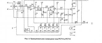
Relay parameters are divided into basic and non-basic. You need to focus on the basic parameters of the relay, because it is they that characterize their operational capabilities and scope of application and ultimately affect the normal operation of the relay.
In turn, the main parameters are divided into:
- Electrical: sensitivity, operating voltage (current), actuation voltage (current), release voltage (current), contact resistance, winding resistance, switching capacity, electrical insulation.
- Temporary: response time, release time, contact bounce time.
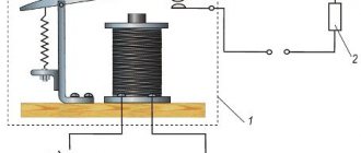
Operating principle
Essentially, a relay is an electromagnet. When control voltage is applied to the coil, the rod attracts the armature, thus switching the circuit.
There are three types of relays:
- with normally closed contacts;
- with normally open;
- throwing over.
When a control signal is applied to a device with normally closed connectors, they open; if there is no signal, they close. For relays with open connectors, the opposite is true. There is voltage on the winding, the terminals close, but when there is no voltage, it opens. In flip-over models there are two sets of connectors, one normally closed and the other normally open. They have a common terminal. When current is applied to the winding, the contacts switch from one position to another.
How to avoid 3 mistakes when selecting and installing a transistor
When selecting a bipolar transistor, you should pay attention to parameter h21. H21 is the gain of the collector current relative to the base current. If the value of this parameter for the transistor is 30, then the analogue should be selected such that the value of h21 is no less than 30.
To determine which npn or pnp transistor structure to use in the circuit, use this simple rule: if the control signal arriving at the base is negative. then type pnp is put, if positive - npn. Please note that the base signal must be of the same polarity as the supply voltage!
The relay has a high self-inductive emf value of several tens of volts when the circuit breaks. Therefore, the collector junction should be protected with a parallel diode. The diode is placed opposite the polarity of the power source: cathode to positive, anode to negative.
DANGEROUS! If this is neglected, the transistor will fail at the first switching.
Video of 12V time delay relay
Functionality check
On the body of each relay there is a diagram with contact numbers and control voltage rating. A rectangle with pins 85 and 86 means a coil. Therefore, when measuring winding parameters, you need to connect to them. Other pins numbered 30, 87 and 87a (88) are the switching key for the external circuit.
It is convenient to use a digital multimeter as a tester for regulator relays and any other electromagnetic relay. This is because it can measure current, voltage and resistance.
Since the performance of the device depends primarily on the health of the winding, the test begins with measuring the coil resistance. Its values range from several tens of ohms to several hundred ohms.
To do this, switch the multimeter to resistance measurement mode. We connect measuring probes to pins 85, 86 and take readings. If the resistance is within normal limits, then you need to check the condition of the controlled outputs. In a relay with normally closed contacts 30 and 87, when measuring the resistance between them, the multimeter should show 0 Ohm. With normally open pins 30 and 87 the resistance between them should be infinity. When the control voltage is applied to the coil terminals 85 and 86, everything should change exactly the opposite.
Sometimes only the actuation current is known, then the coil resistance is measured. After this, the multimeter readings are multiplied by the operating current, and the control action of the winding is obtained. Then, by applying the calculated voltage, you can check the contact group, as described above.
Only AC voltage can be applied to the AC relay coil.
After checking the relay, if there is a need and the ability to adjust the contacts, do so. Otherwise, replace the entire device. Its installation and removal must be carried out with the device's power turned off.
Delay turning off and turning on the relay using a capacitor and 12V resistor
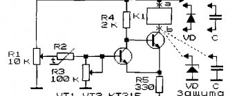
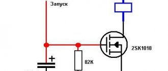
It is not necessary to resort to using integral timers like the NE555 if you only need a delay before start/stop. Using a capacitor paired with a resistor and transistor will solve the problem without complex ICs. Use the diagram below
This is a classic circuit using a capacitor, resistor, diode and bipolar transistor. The circuit uses an NPN type transistor. It works like this: after applying voltage to resistor N resistance, capacitor N capacitor begins to charge. When the bias voltage is reached, the diodes open, and then the control emitter pn junction of the transistor opens, which “opens” the transistor and the current begins to flow in the collector-emitter direction.
Our semiconductor operates in active mode. Until the current controlling the base leaves this mode, the gain will not take on a descending form. This continues until the current value completely crosses the cutoff threshold - the collector-emitter junction closes. When turned on, the opposite happens.
For assembly, it is recommended to use a KT827 transistor with an npn junction. The diode is suitable KD105B or similar in parameters. The capacitor and resistor are selected individually in each case, more on this below.
Application in car
Most often motorists have to deal with switching devices. We are talking about the generator (starter) regulator relay. They remember it when the engine stops starting and it turns out that the battery is discharged. One of the reasons for this is a malfunction of the regulator.
On older cars, to maintain a constant voltage, a regulator was used, consisting of three devices - a voltage stabilizer, a current limiter and a reverse current relay. The regulator prevents the battery from overcharging, which prolongs its service life. It can be built into the starter brush block or performed as a separate module. Its failure may or may not overcharge the battery. In the first case, streaks will be visible on the case, the electrolyte will begin to boil away, which will lead to a voltage drop below 12 volts. In the second, the values will initially be lower than acceptable. As a result, the engine will not start.
Checking the starter regulator
To check the starter regulator relay without removing it from the car, you can use a multimeter and test all the wires that go to it. To do this, they are first disconnected from the regulator. The multimeter is switched to resistance measurement mode, the disconnected wires are checked.
If everything is normal, then the conductors are returned to their place. The voltage at the battery terminals is measured with the engine off. The multimeter is switched to DC voltage measurement mode in the range from 0 to 20 Volts. The probes attach to the battery terminals. The device should show 12.2-12.7 V. If 12 volts or lower, then it needs to be recharged.
Then the engine must be started and checked again with the same measurements. If the voltage is in the range of 13.2-14 V, then this is normal. We add engine speed to 2000 per minute and measure again. Normally, the multimeter should show between 13.6-14.2 V. We also add revolutions to 3500 per minute.
Checking the solenoid relay
When the battery is charged, but the engine does not start, you need to check the starter.
If the generator spins but the engine does not, then in such cases it is necessary to check the solenoid relay of the electric motor and the bendix. To do this, you need to remove the starter. After this, all contacts are cleaned, and the resistance of the relay winding is measured with a multimeter. If the value is infinity, then the winding has burned out. In this case, it is necessary to rewind the coil or replace it. The device shows several tens of ohms, which means the winding is intact.
Then its performance is checked. The positive terminal of the battery is connected to the corresponding relay terminal using the cigarette lighter. And the minus is connected to the starter housing. A click should be heard, then the device is working properly, otherwise it needs to be disassembled and the mechanical part checked.
Purpose of the electrical mechanism. Operating principle
- The engine control system has two power relays: the main relay and the electric fuel pump relay.
- The main relay is designed to supply onboard voltage to all actuating electric mechanisms and sensors of the system, which have a rated supply voltage of 12V.
- The electric fuel pump relay is designed to supply power to the electric fuel pump.
- Both relays are unified in design and are designed to control power circuits up to 30A. Electromagnetic type relay with normally open contacts. The relay is turned on by a signal from the control unit close to ground.
- The power circuit of the main relay coming from the battery is protected from short circuits to ground by a 20 A fuse, and the power circuit from the ignition switch is protected by a 10 A fuse (for UAZ vehicles).
Electric mechanism design
Electrical mechanism parameters
- Power supply range: 8.16V.
- Rated voltage: 12V.
- Control current: no more than 0.2A.
- Operation voltage: not less than 8.0V.
- Release voltage: 1.5. 5.0V.
- Maximum current in the power circuit: 30A.
- Active winding resistance: 80±10 Ohm.
Installation and assembly of the electrical mechanism on the car
- The main relay and the electric fuel pump relay are installed on the front panel above the engine.
- The relay is connected to the wiring harness using four-pin sockets.
- For UAZ vehicles, relay blocks are additionally equipped with blade fuses:
- 20A—on the main relay block;
- 10A—on the electric fuel pump relay block.
- The relays have no visible external differences. The main guideline can be two factors:
- larger cross-section wires are suitable for the main relay block;
- after turning on the ignition, the electric fuel pump relay turns off after about five seconds (if the starter is not turned on), and if you put your hand on the relay body, you will feel a short click when it turns off.
Analogues of electromechanism
- Automotive relay type 90.3747-10 (in a plastic case without mounting flange, 12V-30A) has analogues:
- 90.3747—in a plastic case with a mounting flange;
- 113.3747—in a metal case with a mounting flange;
- 113.3747-10—in a metal case without mounting flange;
- 111.3747—in a metal case with a mounting flange;
- 111.3747-10—in a metal case without mounting flange.
External manifestations of malfunctions in electrical mechanism circuits
Relay connection diagram for a GAZ car.
Scheme for connecting the main relay on a UAZ car.
Electric fuel pump relay connection diagram.
- The malfunction lamp does not light up after turning on the ignition. The electric fuel pump does not turn on. Self-diagnosis records fault codes 177. 179.
- Check the serviceability of the main relay circuits 58, 18, 18a, 18b, 18c, 46.
- The malfunction lamp lights up after turning on the ignition. The electric fuel pump does not turn on. Self-diagnosis records fault codes 167. 169. Check the serviceability of the circuits:
- electric fuel pump relay—18g, 37v, 3;
- electric fuel pump—57, 56.
| In this article I will give several examples of relays used in cars, their differences and some use cases. |
Do-it-yourself 12V turn-on delay relay (RD) on the ne555 and k561ie10 microcircuit
Ne555 - IC, a device for generating pulses at certain intervals, in simple terms - a timer, in technical terms. In the literature, the monovibrator k561ie10 is an analogue of the ne555, but only a dual multivibrator in one housing.
12V turn-on delay relay (RD) on ne555 and k561ie10 microcircuit
Above is a delay circuit for turning on a 12V relay without transistors using the ne555 universal timer. Capacitor C1 and resistor R1 are responsible for the delay time. Use the formula shown in the picture above to calculate the delay time. Note that the constant variable 1.1 is used here and its use is mandatory.
The device works approximately like this: after power is applied, the timer starts, then after the time has elapsed, pin 3 of the OUT chip generates a pulse that closes the relay. Diode VD2 is installed to ensure reliable operation of the relay. VD1 protects the timer from random pulses from the power supply side of the IC.
Automotive timing relay 12 volts with DRL activation delay on 555 timer
We have already considered an example with a turn-off delay using a time-setting RC circuit and a transistor. Now let's do the same thing only using the ne555 timer for DRLs. We will need a ne555 monoborator, 3 25V conductors for 10.22.0.1 µF, one diode of any kind. The pictures below show the upgrade of relay 23.3787. We do everything by analogy. C1 and R1 set the delay. A capacitance of 10 μF and 1.3 MΩ is enough for about 10-13 seconds, so if this is not enough or a lot, we use the formula T = 1.1 * RC for calculation.
Automotive timing relay 12 volts with DRL activation delay on 555 timer
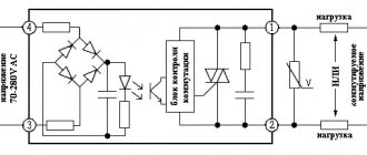
Delay relay circuit on ne555 turn off 24V with your own hands without a transformer
Do not forget that the current PUE regulates the grounding requirements for all devices operating from a 380V network. And devices operating from 42-380V AC must be grounded in places and rooms with increased fire hazard. IEC 364-4-41 requires the grounding of all devices operating at a voltage of 50V and above, and the grounding of devices from 25V in particularly hazardous areas.
Delay relay circuit on ne555 switch off 24V without transformer
According to the principle of operation, the previous circuit differs only in the addition of a voltage multiplier assembled on diodes VD1, VD2 and capacitors C3, C4. The multiplier can only operate in an AC circuit due to the fact that in the first half-cycle, one section of the diode + conductor is charged, and in the second half-cycle, the second assembly is charged. Periodic changes in the direction and magnitude of the current are not typical for constant voltage. Our connectors are connected in series, so the sum of their voltages doubles, and the output becomes 24V.