Relay circuits are used in automatic control systems: to maintain a given temperature, light, humidity, etc. Such circuits are usually similar and contain a sensor, a threshold circuit and an actuator or indicator device as mandatory components (see the list of references).
Relay circuits react to the excess of the controlled parameter above a given (set) level and turn on the actuator (relay, electric motor, one or another device).
It is also possible to notify with a sound or light signal that the controlled parameter has gone beyond the permissible level.
Transistor thermal relay
The thermal relay (Fig. 1) is based on a Schmitt trigger. A thermistor (a resistor whose resistance depends on temperature) is used as a temperature sensor.
Potentiometer R1 sets the initial bias on thermistor R2 and potentiometer R3. By adjusting it, the actuator (relay K1) is activated when the resistance of the thermistor changes.
Rice. 1. Scheme of a simple thermal relay using transistors.
Not only a relay, but also a low-current incandescent lamp can be used as a load in this and other circuits in this chapter.
You can turn on an LED with a series current-limiting resistor of 330...620 Ohms, a sound generator, an electronic siren, etc.
When using a relay, the contacts of the latter can include any load electrically isolated from the sensor circuit: a heating element or, conversely, a fan.
To protect the output transistor from voltage pulses that occur when switching the relay winding (inductive load), it is necessary to connect a semiconductor diode in parallel with the relay winding.
So, in Fig. 1 anode of the diode must be connected to the bottom terminal of the relay winding according to the diagram, the cathode - to the power bus. Instead of a diode, a zener diode or capacitor can be connected with the same result.
● Project 12: Controlling a relay through a transistor
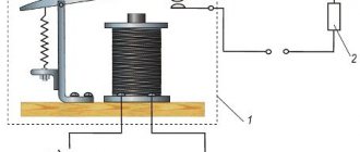
In this experiment, we will get acquainted with a relay with which you can control a powerful load of not only direct current, but also alternating current, with Arduino. Required components: • Arduino UNO R3 controller; • prototyping board; • bipolar transistor S945; • diode 1N4004; • relay; • male-male wires. • male-female wires. A relay is an electrically controlled, mechanical switch that has two separate circuits: a control circuit, represented by contacts (A1, A2), and a controlled circuit, contacts 1, 2, 3 (see Fig. 12.1).
The chains are not connected to each other in any way. A metal core is installed between contacts A1 and A2, and when current flows through it, a movable armature (2) is attracted to it. Contacts 1 and 3 are fixed. It is worth noting that the armature is spring-loaded, and until we pass current through the core, the armature will be pressed against contact 3. When current is applied, as already mentioned, the core turns into an electromagnet and is attracted to contact 1. When de-energized, the spring returns the armature to contact 3 again .When connecting the relay to the Arduino, the microcontroller pin cannot provide the power required for the coil to operate normally. Therefore, you should increase the current - install a transistor. For amplification, it is more convenient to use an NPN transistor connected according to the OE circuit (see Fig. 12.2). With this method, you can connect a load with a higher supply voltage than the power supply to the microcontroller. The resistor on the base is limiting. Can vary within wide limits (1–10 kOhm), in any case, the transistor will operate in saturation mode. The transistor can be any NPN transistor. The gain is practically irrelevant. The transistor is selected based on the collector current (the current we need) and the collector-emitter voltage (the voltage that powers the load).
To turn on a relay connected according to the circuit with an OE, you need to apply 1 to the Arduino pin, and to turn it off - 0. Let's connect the relay to the Arduino board according to the diagram in Fig. 12.3 and write a relay control sketch. Every 5 seconds the relay will switch (turn on/off). When the relay switches, a characteristic click is heard. The contents of the sketch are shown in Listing 12.1.
int relayPin = 10; // connect to Arduino pin D10 void setup() { pinMode(relayPin, OUTPUT); // configure the pin as an output (OUTPUT) } // the function is executed cyclically an infinite number of times void loop() { digitalWrite(relayPin, HIGH); // turn on the relay delay(5000); digitalWrite(relayPin, LOW); // turn off the relay delay(5000); }
Connection order: 1. Connect the elements to the Arduino board according to the diagram in Fig. 12.3. 2. Load the sketch from Listing 12.1 onto the Arduino board. 3. Every 5 seconds, a relay switching click occurs. If you connect the relay contacts, for example, into the gap of a socket with an incandescent lamp connected to a 220 V network, you will see the process of turning on/off the incandescent lamp once every 5 seconds (Fig. 12.3).
Rice. 12.3
Program listings
Simple temperature indicator
The thermal relay (Fig. 3), or, more precisely, the thermal indicator, is made according to a bridge circuit [VRL 83-24]. When the bridge is balanced, none of the LEDs light up. As soon as the temperature rises, one of the LEDs will turn on.
Rice. 3. Schematic diagram of a simple thermal indicator using one transistor and LEDs.
If the temperature, on the contrary, decreases, another LED will light up. To distinguish in which direction the temperature is changing, you can use a red LED to indicate an increase in temperature, and a yellow (or green) LED to indicate a decrease. To balance the circuit, it is better to include a potentiometer instead of resistor R2.
Photo relay with two-stage amplifier
Photo relay circuit shown in Fig. 5 contains a two-stage DC amplifier made of transistors of different conductivity types.
Rice. 5. Schematic diagram of a photo relay with a two-stage amplifier.
When the electrical resistance of the photodiode and, accordingly, the bias at the base of the transistor VT1 changes, the collector current of the output transistor of the amplifier VT2 will increase, and the voltage across the resistor R2 will increase.
As soon as this voltage exceeds the breakdown voltage of the threshold element - the semiconductor zener diode VD2, the final stage on the transistor VT3 is turned on, controlling the operation of the actuator (relay).
The use of a threshold element (semiconductor zener diode) in the circuit increases the clarity of the photo relay operation.
Pnp transistor in switch mode
Transistor operation in switch mode is basic in all electronics, especially digital electronics.
Where it all began
Previously, when there were no super-powerful computers and super-fast Internet, messages were transmitted using Morse code. Morse code used three characters: a dot, a dash and... a pause. To transmit messages over long distances, the so-called telegraph KEY was used.
They pressed the big black little button and the current began to flow; when they pressed it down, the circuit broke and the current stopped flowing. ALL! That is, by changing the speed and duration of pressing the button, we can encode any message. Press the button - there is a signal, press the button - there is no signal.
Transistor switch
A key assembled on a transistor is called a transistor switch . The transistor switch performs only two operations: ON and OFF ; we will consider the intermediate mode between “on” and “off” in the following chapters. An electromagnetic relay performs the same function, but its switching speed is very slow from the point of view of modern electronics, and the switching contacts wear out quickly.
What is a transistor switch? Let's take a closer look:
This is a familiar pattern, isn't it? Everything is elementary and simple here