Load control 220 volts WITHOUT relays! 58
Using optothyristors
Optosimistors MOS301x, MOS302x, MOS303x, MOS304x, MOS306x, MOS308x Optosimistors belong to the class of optocouplers and provide very good galvanic isolation (about 7500 V) between the control circuit and the load. These radioelements consist of an infrared LED connected via an optical channel to a bidirectional silicon triac. The latter can be supplemented with an unlocking circuit that is triggered when the supply voltage passes through zero. These radioelements are especially indispensable when controlling more powerful triacs, for example, when implementing high voltage or high power relays. Such optocouplers were conceived to communicate between logic circuits with low voltage levels and a load powered by a mains voltage of 220 V. The optosimistor can be placed in a small-sized DIP package with six pins; its pinout and internal structure are shown in Fig. 1.
The table shows the classification of optosimistors according to the magnitude of the forward current through the IFT LED, which opens the device, and the maximum forward repeating voltage that the triac can withstand at the output (VDRM). The table also notes the property of the triac to open when the supply voltage passes through zero. To reduce interference, it is preferable to use triacs that open when the supply voltage passes through zero.
As for elements with zero supply voltage detection, their output stage is triggered when the supply voltage exceeds a certain threshold, usually 5 V (maximum 20 V). The MOS301x and MOS302x series are more often used with resistive loads or in cases where the load supply voltage must be turned off. When a triac is in a conducting state, the maximum voltage drop across its terminals is usually 1.8V (maximum 3V) at a current of up to 100mA. The holding current (IH), which maintains the conductivity of the output stage of the optosimistor, is equal to 100 μA, whatever it is (negative or positive) during the half-cycle of the supply voltage. The off-state leakage current of the output stage (ID) varies depending on the optosimistor model. For optosimistors with zero detection, the leakage current can reach 0.5mA if the LED is energized (current flowing IF). The infrared LED has a reverse leakage current of 0.05 µA (maximum 100 µA), and a maximum forward voltage drop of 1.5 V for all optosimistor models. The maximum permissible LED reverse voltage is 3 volts for models MOS301x, MOS302x and MOS303x and 6 volts for models MOS304x. MOSZO6x and MOSZO8x. Maximum permissible characteristics The maximum permissible current through the LED in continuous mode is no more than 60mA. The maximum pulse current in the conducting state of the output stage switch is no more than 1 A. The total power dissipation of the optosimistor should not exceed 250 mW (maximum 120 mW for the LED and 150 mW for the output stage at T - 25˚C).
Application of optosimistors
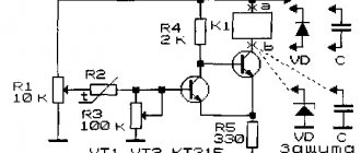
Figure 2 a-e shows various diagrams of typical applications of optosimistors, differing from each other in the nature of the load and the methods of connecting the load and power. Resistance Rd The calculation of the resistance of this resistor depends on the minimum forward current of the infrared LED, which guarantees the triggering of the triac. Therefore, Rd = (+V - 1.5) / IF. For example, for a transistor control circuit for an optosimistor with a supply voltage of +5 V (Fig. 3) and an open transistor voltage (Uke us) equal to 0.3 V, +V will be 4.7 V, and IF should be in the range between 15 and 50 ma for MOS3041. You should take IF - 20 mA, taking into account the decrease in LED efficiency over the service life (5 mA reserve), fully ensuring the operation of the optocoupler with a gradual weakening of the current. Thus, we have: Rв = (4.7 - 1.5) / 0.02 = 160 Ohm. You should select a standard resistance value, that is, 150 Ohms for MOS3041 and a resistance of 100 Ohms for MOS3020. Resistance R Resistor R does not need to be included when the load is purely resistive. However, if the triac is protected by an RP - CP circuit, most often called a spark-extinguishing circuit, resistor R makes it possible to limit the current through the control electrode of the optosimistor. Indeed, in the case of an inductive load, the current passing through the triac and the voltage applied to the circuit are in antiphase. Since the triac ceases to be a conductor when the current passes through zero, the CP protection circuit capacitor can discharge through the optosimistor. Then resistor R limits this discharge current. The minimum value of its resistance depends on the maximum voltage of the capacitor and the maximum permissible current for the optosimistor, therefore for a supply voltage of 220 V: Rmin = 220 V x 1.41 / 1A - 311 Ohm. On the other hand, too large an R value can lead to malfunction. Therefore, they take R - 330 or 390 Ohms. Resistance RG Resistor RG is needed only when the input resistance of the control electrode is very high, that is, in the case of a sensitive triac. The value of resistor RG can be in the range from 100 to 500 ohms. Resistors RG and R introduce a delay in unlocking the triac, which will be more significant the higher the resistance of these resistors. Chain Ra - Ca To limit the rate of change of voltage dV/dt at the output of the optosimistor, a snubber chain is needed (Fig. 2 d). The choice of the value of the resistor Ra depends on the sensitivity of the triac and the voltage Va, starting from which the triac should operate. Thus, we have: R + Ra = Va / IG. For a triac with control current IG = 25mA and trigger voltage Va = 20V, we obtain: R + Ra = 20 / 0.025 - 800 Ohm or: Ra = 800 - 330 = 470 Ohm. In order for the triac to switch quickly, the following condition must be met: dV / dt = 311 / Ra x Ca. For MOS3020, the maximum dV / dt value is 10 V/µs. Thus: Ca = 311 / (470 x 107) = 66 nF. We choose: Ca = 68 nF. Comment. As for the snubber chain, experimental values are generally preferable to theoretical calculations. Protection It is strongly recommended to protect the triac and optosimistor when operating on an inductive load or when interference frequently affects the network. For a triac, a spark-extinguishing RC circuit is simply necessary. For an optosimistor with zero detection, such as the MOS3041, this is desirable. The resistance of resistor R should be increased from 27 Ohms to 330 Ohms (except for the case when the controlled triac is insensitive). If a model without zero detection is used, then the snubber chain Ra - Ca is required.
Electronics for everyone
| Triac BT139 |
| Connection diagram from datasheet on MOC3041 |
If you look at it on your fingers, then a thyristor is similar to a diode , even the designation is similar. It allows current to flow in one direction and does not allow it to flow in the other. But it has one feature that fundamentally distinguishes it from a diode - control input . If opening current , then the thyristor will not pass current even in the forward direction. But as soon as you give even a brief impulse, it immediately opens and remains open as long as there is direct voltage. If the voltage is removed or the polarity is changed, the thyristor will close .
The polarity of the control voltage should preferably match the polarity of the anode voltage. If you connect two thyristors back-to-back in parallel , you get a triac - an excellent thing for switching loads on alternating current.
On the positive half-wave of the sinusoid one passes, on the negative half-wave the other. Moreover, they pass only if there is a control signal. If the control signal is removed, then in the next period both thyristors will shut down and the circuit will break. Beauty and nothing more. So it should be used to control household loads.
But there is one subtlety here - we are switching a high-voltage power circuit, 220 volts. And our controller is low-voltage , it operates at five volts. Therefore, in order to avoid excesses, it is necessary to make a potential decoupling . That is, make sure that there is no direct electrical connection between the high-voltage and low-voltage parts. For example, make optical separation . There is a special assembly for this - triac optodriver MOC3041 . Wonderful thing! Look at the connection diagram - just a few additional parts and you have the power and control parts separated from each other. The main thing is that the voltage for which the capacitor is designed is one and a half to two times higher than the voltage in the outlet. You don’t have to worry about power interference when you turn the triac on and off. In the optodriver itself, the signal is supplied by an LED, which means you can safely light it from the microcontroller pin without any additional tricks.
In general, it is possible without decoupling and it will also work, but it is considered good form to always make a potential decoupling between the power and control parts. This includes the reliability and safety of the entire system. Industrial solutions are simply filled with optocouplers or all sorts of isolating amplifiers.
BT139 as a triac - with a good radiator, this thing can easily carry a current of 16A through itself
Controlling a 220V light bulb on Arduino
November 04, 2017
Everyone knows that Arduino pins are capable of supplying a voltage of 3.3V or 5V to the modules or sensors connected to them. For example, we can connect temperature and humidity sensors and a display to our microcontroller - we get a miniature weather station with data displayed on the screen; or we can measure the distance to various objects using an ultrasound sensor. However, what about lighting control? After all, the power from Arduino is enough for ordinary LEDs, but not for light bulbs (whether incandescent, energy-saving or LED). Let's solve this problem using a relay!
Let's start with the fact that the light bulbs we are talking about in this article are most often powered from a 220V network. Moreover, it’s hard to imagine connecting a light bulb directly to the board, because it will be too unusual compared to connecting diodes.
The same problem usually occurs with connecting other devices that receive power from the network. A device called a relay comes to the rescue.
Relay modules are inexpensive and can have from one to several channels. The photo below shows a single-channel relay module, which is ready to be connected to Arduino.
This module can be freely connected to Arduino, since it requires an operating voltage of 5 volts, but the relay can switch several different values. Most often they are written on the case: most often this is free switching up to 10A 30V DC and 10A 250V AC.
The relay is a controlled switch that, based on a signal from the Arduino, switches the middle contact between the two extreme ones, thus opening or closing the circuit.
To connect to the Arduino, 3 pins are used: two power pins (5V and Gnd) and a control pin, which connects to a digital pin on the board (for example, pin number 3). On the other side of the relay itself there are three more contacts, but for connecting a load (for example, a light bulb) - the light bulb control contacts are connected to two of them, and the other remains free (inside the relay itself it is connected to ground). Therefore, when the relay is turned on, the COM (common) and NC (normally closed) contacts are closed and the light comes on, and when the relay is turned off, other contacts are closed - COM (common) and NO (normally open). Do not forget that the contacts of the light bulb must also be connected to a 220V network
The connection diagram is shown in the picture below:
After we have assembled the circuit, we connect the board to the computer and download the following program code (it is very simple):
const int relPin = 3; void setup() { pinMode(relPin, OUTPUT); } void loop() { digitalWrite(relPin, HIGH); delay(1000); digitalWrite(relPin, LOW); delay(3000); }
First, we set the relPin variable, the relay module is connected to pin 3. Next, the signal from the relay is set as output. And in the program cycle, we turn on the relay, after a second it turns off and after 3 seconds it turns on again
And you can control other devices in the same way. Now you know how to connect a light bulb to Arduino via a relay and can program various devices on this basis. For example, turn on the light automatically using a motion sensor (when there is movement, the light turns on) or using a light sensor (when it becomes dark, the light turns on), etc.
The disadvantages of this type of relay include high current consumption, low survivability under heavy loads and possible sticking of contacts if a large load was connected (for example, a boiler or something similar)
A solid-state relay will not have such disadvantages: instead of a coil there is a semiconductor.
This concludes this article. Thank you all for your attention and successful compilation!
You can buy the components used in the article on our website: Amperkot.ru
This article is the property of Amperkot.ru. When reprinting this material, an active link to the original source, not closed for indexing by search engines, is required.