People use electric energy in almost all areas of their activities. Nowadays it is difficult to imagine life without electricity, which is converted from mechanical energy with the help of special equipment. Let's take a closer look at how this process occurs and how modern generators are designed.
Design and design of an alternating current generator
A standard electric generator has the following components:
- The frame to which the stator with electromagnetic poles is attached. It is made of metal and must perform the protective function of all elements of the mechanism.
- The stator to which the winding is attached. It is made of ferromagnetic steel.
- A rotor is a moving element on the core of which there is a winding that generates electric current.
- A switching unit that removes electricity from the rotor. It is a system of movable conductive rings.
Depending on the purpose, the generator has certain design features, but there are two components that any device that converts mechanical energy into electricity has:
- The rotor is a movable one-piece piece made of iron;
- The stator is a stationary element that is made of iron sheets. Inside it there are grooves, inside of which there is a wire winding.
To obtain greater magnetic induction, there should be a small distance between these elements. By design, generators are:
- With a moving armature and a static magnetic field.
- With a fixed armature and a rotating magnetic field.
Operating principle of the generator
The principle of operation of the generator is based on the law of electromagnetic induction, according to which when a conductor moves in a magnetic field, when the conductor crosses magnetic lines of force in the conductor, an EMF is induced, proportional to the magnitude of electromagnetic induction, the speed of movement of the conductor, and the length of the conductor in the magnetic field:
E=BlV × sinά, where ά is the angle between the direction of movement of the conductor and the direction of the magnetic lines of force. Thus, the maximum value of the emf is obtained when the angle ά
= 90°, that is, the movement occurs at a right angle.
At ά
= 0° the conductor slides along the magnetic lines of force and no emf is induced.
The direction of the current in a conductor in a closed circuit can be determined by the rule of the right hand: If the right hand is placed between the poles of a magnet so that the lines of force enter the palm, and the thumb moved to the side coincides with the direction of movement of the conductor, then the remaining fingers will show the direction of the current.
Let's consider the processes occurring in a conductor in the form of a frame that is forced to rotate in the field of a permanent magnet (Fig. 3.1. and 3.2.).
If the frame is initially located in a horizontal plane, the angle between the power lines and the direction of movement of the frame conductors ά
= 0°, respectively, and EMF = 0. As the frame rotates, a component of the conductor motion vector appears, perpendicular to the magnetic lines of force.
Fig.3.1. Rotation of the frame in the field of a permanent magnet.
An EMF also appears, which, as the frame rotates, increases according to the law of a sine wave, since according to the law of a sine, the component of the motion of the conductors, perpendicular to the magnetic lines of force, increases. When the frame is rotated at an angle of 90°, the angle between the direction of movement and the magnetic lines of force is 90°. In this case, the EMF reaches its maximum value. With further rotation of the frame, the component of the vector of movement of the conductors, perpendicular
Rice. 3.2. Changing the direction of movement of the frame branches when it rotates
polar with respect to the magnetic field lines begins to decrease again, the value of sinά , which leads to a decrease in the emf. At ά
=180°
sinά
= 0
.
Thus, when the frame is rotated through an angle from 0° to 180°, the EMF first increases, reaching a maximum at an angle of 90°, and then decreases to zero. Then the process is repeated. But due to the fact that the component of the motion vector, perpendicular to the magnetic lines of force, is directed in the opposite direction, the speed now has a “-” (minus) sign. The graph of changes in EMF depending on the angle of rotation of the frame is a sinusoid (Fig. 3.3).
Thus, an alternating current is obtained at the output of the device, the frequency of which is directly proportional to the rotation speed of the frame.
To obtain direct current, it is necessary to use a device that switches the frame conductors when the EMF reaches zero.
Rice. 3.3. Dependency E
from the angle of rotation of the frame.
Such a device in generators and DC electric motors is called a collector. For a frame, the simplest commutator is two half-rings 3 , which are connected to the ends of the frame conductors (Fig. 3.4). Brushes 4 , which with a certain force are pressed against the surface of the half-rings (commutator surface), forming a sliding contact. The brushes, in turn, are connected to an external electrical circuit.
Rice. 3.4. The principle of constructing a DC generator
As discussed earlier, when the frame is in a horizontal plane, the emf is zero. When the frame rotates, the EMF begins to increase and reaches a maximum when turning through an angle of 90°, after which it begins to decrease and when turning through an angle of 180° it becomes equal to zero.
In this case, the frame occupies the same position as at the initial moment of time. The only difference is that the branches of the frame have swapped places. Therefore, as the frame continues to rotate, the EMF will begin to increase again, which ensures commutation using a collector. In this case, the graph of the dependence of the EMF on the angle of rotation will consist only of positive half-waves. Thus, a pulsating current is obtained from alternating current.
Rice. 3.5. Dependence E
from the angle of rotation of the frame when using two half rings
If we take two frames located at an angle of 90° to each other, and imagine the collector as a ring cut into four parts, then the graph of the EMF depending on the angle of rotation of the frame will look like an envelope for two identical graphs constructed for the same frame (Fig. 3.5), with a shift of 90°. Thus, the dependence of the EMF on the angle of rotation will look like a relatively small pulsation relative to the average level.
Rice. 3.6. Dependence E
from the rotation angle when using two frames located at an angle of 90° to each other
By increasing the number of frames (the number of turns of the generator's armature winding) and the number of contact elements of the collector, it is possible to obtain an almost constant EMF value.
A real generator consists of three functional units:
— stator;
- rotor (armature);
— collector-brush unit.
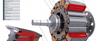
The stator (Fig. 3.7.) is a stationary part of the generator with field winding coils, poles and a brush holder made in it. At the end of the stator there is a bearing shield. A pipe connected to a special air intake on the engine nacelle is attached to one of the end parts for supplying cooling air. On the opposite side, heated air exits through the blinds.
Fig.3.7. DC generator device
1 – collector; 2 – brushes; 3 armature core; 4 – main pole; 5 – field winding coil; 6 – body; 7 – bearing shield; 8 fan; 9 – armature winding.
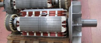
The armature (rotor) is located inside the stator. Its shaft rotates on ball bearings. At the armature there is a working winding of the generator, in the turns of which an EMF is induced similar to that considered. To remove electricity, a collector (1) is installed on the armature shaft, which is made in the form of a cylinder with plates of hard-drawn copper located on it. At the opposite end of the shaft there is a fan impeller (8), which ensures forced cooling of the generator on the ground when the aircraft is stationary.
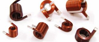
The commutator-brush assembly includes a commutator and a brush holder with brushes located in it (2). Brushes (Fig. 3.8) are made of materials containing carbon, providing low electrical resistance and high wear resistance. The brushes move freely inside the brush holders and, using calibrated springs, are pressed against the commutator surface with a given force. The commutator-brush assembly is the weak point of the DC generator. During operation, it is necessary to control the height of the brushes and the condition of the commutator in order to determine the degree of their wear. With increased
Fig.3.8. Low (a) and high (b) power brushes.
The degree of wear of the brushes may cause them to freeze, which can lead to generator failure in flight.
The presence of a commutator-brush assembly is the main disadvantage of DC generators. When transmitting high power through a sliding contact, intense sparking and burnout of both the brushes and the commutator occur. In world practice, a power limit of 18 kW is accepted for aircraft DC generators.
The principle of operation of the generator is based on the law of electromagnetic induction, according to which when a conductor moves in a magnetic field, when the conductor crosses magnetic lines of force in the conductor, an EMF is induced, proportional to the magnitude of electromagnetic induction, the speed of movement of the conductor, and the length of the conductor in the magnetic field:
E=BlV × sinά, where ά is the angle between the direction of movement of the conductor and the direction of the magnetic lines of force. Thus, the maximum value of the emf is obtained when the angle ά
= 90°, that is, the movement occurs at a right angle.
At ά
= 0° the conductor slides along the magnetic lines of force and no emf is induced.
The direction of the current in a conductor in a closed circuit can be determined by the rule of the right hand: If the right hand is placed between the poles of a magnet so that the lines of force enter the palm, and the thumb moved to the side coincides with the direction of movement of the conductor, then the remaining fingers will show the direction of the current.
Let's consider the processes occurring in a conductor in the form of a frame that is forced to rotate in the field of a permanent magnet (Fig. 3.1. and 3.2.).
If the frame is initially located in a horizontal plane, the angle between the power lines and the direction of movement of the frame conductors ά
= 0°, respectively, and EMF = 0. As the frame rotates, a component of the conductor motion vector appears, perpendicular to the magnetic lines of force.
Fig.3.1. Rotation of the frame in the field of a permanent magnet.
An EMF also appears, which, as the frame rotates, increases according to the law of a sine wave, since according to the law of a sine, the component of the motion of the conductors, perpendicular to the magnetic lines of force, increases. When the frame is rotated at an angle of 90°, the angle between the direction of movement and the magnetic lines of force is 90°. In this case, the EMF reaches its maximum value. With further rotation of the frame, the component of the vector of movement of the conductors, perpendicular
Rice. 3.2. Changing the direction of movement of the frame branches when it rotates
polar with respect to the magnetic field lines begins to decrease again, the value of sinά , which leads to a decrease in the emf. At ά
=180°
sinά
= 0
.
Thus, when the frame is rotated through an angle from 0° to 180°, the EMF first increases, reaching a maximum at an angle of 90°, and then decreases to zero. Then the process is repeated. But due to the fact that the component of the motion vector, perpendicular to the magnetic lines of force, is directed in the opposite direction, the speed now has a “-” (minus) sign. The graph of changes in EMF depending on the angle of rotation of the frame is a sinusoid (Fig. 3.3).
Thus, an alternating current is obtained at the output of the device, the frequency of which is directly proportional to the rotation speed of the frame.
To obtain direct current, it is necessary to use a device that switches the frame conductors when the EMF reaches zero.
Rice. 3.3. Dependency E
from the angle of rotation of the frame.
Such a device in generators and DC electric motors is called a collector. For a frame, the simplest commutator is two half-rings 3 , which are connected to the ends of the frame conductors (Fig. 3.4). Brushes 4 , which with a certain force are pressed against the surface of the half-rings (commutator surface), forming a sliding contact. The brushes, in turn, are connected to an external electrical circuit.
Rice. 3.4. The principle of constructing a DC generator
As discussed earlier, when the frame is in a horizontal plane, the emf is zero. When the frame rotates, the EMF begins to increase and reaches a maximum when turning through an angle of 90°, after which it begins to decrease and when turning through an angle of 180° it becomes equal to zero.
In this case, the frame occupies the same position as at the initial moment of time. The only difference is that the branches of the frame have swapped places. Therefore, as the frame continues to rotate, the EMF will begin to increase again, which ensures commutation using a collector. In this case, the graph of the dependence of the EMF on the angle of rotation will consist only of positive half-waves. Thus, a pulsating current is obtained from alternating current.
Rice. 3.5. Dependence E
from the angle of rotation of the frame when using two half rings
If we take two frames located at an angle of 90° to each other, and imagine the collector as a ring cut into four parts, then the graph of the EMF depending on the angle of rotation of the frame will look like an envelope for two identical graphs constructed for the same frame (Fig. 3.5), with a shift of 90°. Thus, the dependence of the EMF on the angle of rotation will look like a relatively small pulsation relative to the average level.
Rice. 3.6. Dependence E
from the rotation angle when using two frames located at an angle of 90° to each other
By increasing the number of frames (the number of turns of the generator's armature winding) and the number of contact elements of the collector, it is possible to obtain an almost constant EMF value.
A real generator consists of three functional units:
— stator;
- rotor (armature);
— collector-brush unit.
The stator (Fig. 3.7.) is a stationary part of the generator with field winding coils, poles and a brush holder made in it. At the end of the stator there is a bearing shield. A pipe connected to a special air intake on the engine nacelle is attached to one of the end parts for supplying cooling air. On the opposite side, heated air exits through the blinds.
Fig.3.7. DC generator device
1 – collector; 2 – brushes; 3 armature core; 4 – main pole; 5 – field winding coil; 6 – body; 7 – bearing shield; 8 fan; 9 – armature winding.
The armature (rotor) is located inside the stator. Its shaft rotates on ball bearings. At the armature there is a working winding of the generator, in the turns of which an EMF is induced similar to that considered. To remove electricity, a collector (1) is installed on the armature shaft, which is made in the form of a cylinder with plates of hard-drawn copper located on it. At the opposite end of the shaft there is a fan impeller (8), which ensures forced cooling of the generator on the ground when the aircraft is stationary.
The commutator-brush assembly includes a commutator and a brush holder with brushes located in it (2). Brushes (Fig. 3.8) are made of materials containing carbon, providing low electrical resistance and high wear resistance. The brushes move freely inside the brush holders and, using calibrated springs, are pressed against the commutator surface with a given force. The commutator-brush assembly is the weak point of the DC generator. During operation, it is necessary to control the height of the brushes and the condition of the commutator in order to determine the degree of their wear. With increased
Fig.3.8. Low (a) and high (b) power brushes.
The degree of wear of the brushes may cause them to freeze, which can lead to generator failure in flight.
The presence of a commutator-brush assembly is the main disadvantage of DC generators. When transmitting high power through a sliding contact, intense sparking and burnout of both the brushes and the commutator occur. In world practice, a power limit of 18 kW is accepted for aircraft DC generators.
Classification and types of generators
All electric generators can be classified according to operating criteria and the type of fuel from which electricity is generated. All generators are divided into single-phase (voltage output 220 Volts, frequency 50 Hz) and three-phase (380 Volts with a frequency of 50 Hz), as well as according to the operating principle and type of fuel that is converted into electricity. Generators can also be used in various fields, which determines their technical characteristics.
According to the operating principle
There are asynchronous and synchronous alternating current generators.
Asynchronous
Asynchronous electric generators do not have an exact dependence of the EMF on the rotor speed, but a term such as “slip S” works here. It makes that difference. The amount of slip is calculated, so there is still some influence of the generator elements in the electromechanical process of the asynchronous motor.
Synchronous
Such a generator has a physical dependence on the rotational movement of the rotor to the generated frequency of electricity. In such a device, the rotor is an electromagnet consisting of cores, windings and poles. The stator are coils that are connected according to the star principle and have a common point - zero. It is in them that electric current is generated. The rotor is driven by an extraneous force of moving elements (turbines), which move synchronously. The excitation of such an alternating current generator can be either contact or non-contact.
By engine fuel type
With the advent of generators, distance from the power grid no longer becomes an obstacle to using electrical appliances.
Application area
Alternating current is widely used. Today, almost all household appliances and industry operate on alternating current. This is due to the fact that alternating current is transmitted over long distances, with much less losses than direct current. Also, alternating current is easily converted to direct current using diode rectifiers. Direct current cannot be converted to alternating current.
Alternating current generators are used in all power plants.
Industrial alternating current electric generators are used to provide emergency autonomous power supply to hospitals, schools, kindergartens, commercial and industrial facilities. Also, industrial generator sets are used in the construction of new facilities, this allows the use of electrical equipment in areas where there are no other sources of electricity.
In household diesel and gasoline installations for various purposes. This includes providing autonomous power in the event of a power outage, and obtaining it in places where there is no power line.
How does an electric generator work?
The operation of an electric generator consists of the interaction of the stator, rotor and slip rings. The stator remains motionless when the generator is turned on. The distance between the stator and the rotor is only a few millimeters, so a very strong magnetic field arises between them, and a high-power electric current appears in the rotor winding. When voltage is applied from an external source, the stator winding turns into an electromagnet.
The rotor is connected to the shaft of a mechanical device (internal combustion engine, wind or water engine, etc.) and rotates while the generator is running. The rotor winding, as it moves, constantly crosses the magnetic field created by the stator windings, and an electric current is generated in it.
This design made it possible to get rid of large and heavy permanent magnets. Slip rings are designed to remove electrical energy from the rotor windings. They are a drum with many copper plates to which the rotor windings are connected. Graphite brushes are in contact with them on the outside, to which an electrical energy consumer is connected via wires.
Generator device