Electrical device design
Transformation of three-phase current does not necessarily imply the use of one transformer having a common magnetic circuit. Although such installations are widely used in the national economy.
There is the possibility of such a transformation using three separate single-phase transformers that are not magnetically connected to each other, that is, each individual phase will have its own separate magnetic circuit.
A transformer made according to this scheme is called a group transformer. The primary and secondary windings of the device are interfaced with each other according to one of the schemes adopted for transforming three-phase current.
Structurally, a three-phase transformer is a three-rod magnetic circuit with windings located on each of the rods, made in the same way as for single-phase devices.
Interesting material on the topic: how a toroidal transformer works.
Let's imagine three single-phase transformers placed next to each other so that their three rods form one common central rod. On each of the other three rods there are primary and secondary windings.
The currents in the transformer coils will create time-varying magnetic fluxes, which will each be closed in its own magnetic circuit. In the central composite rod, the magnetic fluxes will add up and give a total of zero, because these fluxes are created by symmetrical three-phase currents, regarding which we know that the sum of their instantaneous values is equal to zero at any moment of time.
Let us assume that the primary coils of all transformer bars are exactly the same and wound in the same direction. We connect all the upper ends of the coils to neutral O, and connect the lower ends of the coils to the three terminals of the three-phase network. The magnetic cores are made of sheet electrical steel. To weaken eddy currents and reduce magnetization reversal losses, steel sheets are insulated with varnish before assembly.
Detailed design of a three-phase transformer.
General structure and principle of operation
Each transformer is equipped with two or more windings inductively coupled to each other. They can be wire or tape, covered with an insulating layer. The windings are wound on a core, also known as a magnetic circuit, made of soft ferromagnetic materials. If there is one winding, such a device is called an autotransformer.
The operating principle of the transformer is quite simple and understandable. An alternating voltage is applied to the primary winding of the device, which leads to the flow of alternating current in it. This alternating current, in turn, causes the creation of an alternating magnetic flux in the magnetic circuit. Under its influence, an alternating electromotive force (EMF) is induced in the primary and secondary windings. When the secondary winding closes to the load, alternating current also begins to flow through it. This current in the secondary system differs in its own parameters. It has individual current and voltage indicators, number of phases, frequency and voltage waveform.
Energy systems that transmit and distribute electricity use power transformers. With the help of these devices, the values of alternating current and voltage are changed. However, the frequency, number of phases, current or voltage curve remain unchanged.
The design of the simplest power transformer includes a magnetic core made of ferromagnetic materials, mainly electrical steel sheets. The primary and secondary windings are located on the magnetic core rods. The primary winding is connected to the AC source, and the secondary winding is connected to the consumer.
In power transformers, when flowing through the turns of the winding, an alternating magnetic flux is also created, which arises in the magnetic core. Under its influence, an EMF is induced in both windings. The output voltage may be higher or lower than the original voltage, depending on whether a step-up or step-down transformer is used. The EMF value in each winding varies according to the number of turns. Thus, if you create a certain ratio of turns in the windings, you can create a transformer with the required ratio of input and output voltages.
Magnetic Circuit Location
Three-phase core transformers are divided into transformers with a symmetrical magnetic circuit and transformers with an asymmetrical magnetic circuit. The arrangement of the rods in the same plane leads to the fact that the magnetic resistance for the middle phase flow is less than for the outer phase flows.
Indeed, the magnetic fluxes of the extreme phases travel along slightly longer paths than the flux of the middle phase. In addition, the flow of extreme phases, having left their rods, passes completely in one half of the yoke, and only in the other half (after branching into the middle rod) does half of it pass. The flow of the middle phase, upon exiting the vertical rod, immediately branches into two halves, and therefore only half of the flow of the middle phase passes through both parts of the yoke.
Thus, the flows of the extreme phases saturate the yoke to a greater extent than the flow of the middle phase, and therefore the magnetic resistance for the flows of the extreme phases is greater than for the flow of the middle phase.
A consequence of the inequality of magnetic resistances for the flows of different phases of a three-phase transformer is the inequality of no-load currents in individual phases at the same phase voltage. However, with low saturation of the iron of the yoke and good assembly of the iron of the rods, this inequality of currents is insignificant.
Since the design of transformers with an asymmetrical magnetic circuit is much simpler than that of a transformer with a symmetrical magnetic circuit, the first transformers found their primary application. Transformers with a symmetrical magnetic circuit are rare.
It will be interesting➡ The design of a toroidal transformer and its advantages
Main types of device
The main group of three-phase transformers are armored transformers. An armored three-phase transformer can be considered as consisting of three single-phase armored transformers, placed one next to the other with their yokes. It can be divided into three single-phase armored transformers, the magnetic fluxes of which can each be closed along its own magnetic circuit.
In core transformers, the windings are almost entirely open and therefore more accessible for inspection and repair, as well as for the cooling medium. There are a number of advantages and disadvantages based on which type of transformer is chosen.
Pros and cons of armored transformers over rod transformers.
The devices are switched according to various winding connection schemes. Group three-phase transformers are used in the presence of very high powers, from 630 kVA per phase.
Using a group transformer under such conditions is advisable because the dimensions and weight of the product are significantly smaller than a similar unit operating at the total power of the group.
Moreover, when using a single transformer, in order to have reserve power, you have to install another similar device, and in a group transformer, one of three single-phase ones can be used as a backup.
This determines the choice of group transformers for the stated purposes, despite the fact that they have lower efficiency, larger dimensions and are somewhat more expensive compared to single analogues.
You can read more about the design of transformers in the material on current transformers.
Types of winding
- The screw winding runs in a spiral with oil cooling channels. In power three-phase transformers they are used for low voltages. A spacer is placed between the layers.
- Continuous winding gets its name from its method: many windings are wound with one piece of copper wire. Often the outer coil is placed first, followed by relaying.
- The intertwined winding, due to the interlacing of adjacent turns, is characterized by high mechanical strength.
- The cylindrical layer winding resembles a screw winding; the turns are placed end-to-end without intermediate channels for cooling.
- The disk coil winding is similar to the continuous one, the difference is limited by the additional insulation applied separately for each coil. It has great mechanical strength.
Rod type magnetic core
To power radio-electronic devices, three-phase transformers with a common magnetic system through a yoke I for three phases with three rods C, or three-rod transformers are usually used. Each of the transformer windings, both primary and secondary, can be connected: a) by a star; b) a triangle.
When connected by a star, the ends of the windings form a common point 0. When connected by a triangle, the beginning of the first phase winding is connected to the end of the third, the beginning of the second - to the end of the first, and the beginning of the third - to the end of the second. In the first case, everything starts, and in the second, the common points of the windings are connected to the network.
It should be noted that the concepts of the beginning and end of the windings are conventional, but they are necessary for the correct connection of the phase windings. In three-phase transformers, the positive direction of the current from the beginning to the end of the winding must correspond to a certain direction of the magnetic flux in the rods; in core transformers this direction must be the same.
Winding connection: a - star; b - triangle.
The beginnings of high voltage (HV) phase windings are usually designated by capital (capital) letters A, B and C, and their ends by letters X, Y and Z, and for phase windings the letters AX, VU and CZ are used. The beginnings and ends of low voltage (LV) windings are designated, respectively, by lowercase (small) letters - a, b, c and x, y, g.
The most common winding connections are “star” (Y) and “delta” (D), and the primary and secondary windings can have either the same or different circuits. If, when connecting the windings with a star, the zero point is output, then such a connection is called “star with zero” (Yo).
Star connection of windings
The simplest and cheapest of them is to connect both windings of the transformer with a star (Y/Y), in which each of the windings and its insulation (with solid grounding of the neutral point) should be designed only for phase voltage and line current.
Star connection of transformer windings.
Since the number of turns of a transformer winding is directly proportional to the voltage, therefore, a star connection of the windings requires a smaller number of turns in each winding, but a larger cross-section of conductors with insulation designed only for phase voltage.
A three-phase transformer has windings connected in a star (Y/Y). This connection is widely used for small and medium power transformers (up to approximately 1800 kVA). The star connection is most desirable for high voltage, since in it the insulation of the windings is calculated only for the phase voltage. The higher the voltage and lower the current, the relatively more expensive it is to connect the windings with a delta.
Where is triangle winding used?
Connecting the windings with a triangle is structurally more convenient at high currents. For this reason, the Y/D connection is widely used for high power transformers where a neutral wire is not required on the low voltage side.
With three-phase transformation, only the ratio of phase voltages U1ph/U2ph is always approximately equal to the ratio of the numbers of turns of the primary and secondary windings w1/w2; As for linear voltages, their ratio depends on the method of connecting the transformer windings.
Connection of transformer windings with a triangle.
With the same connection method (Y/Y or D/D), the ratio of line voltages is also equal to the transformation ratio. However, with different connection methods (Y/D or D/Y), the line-to-line voltage ratio is √3 times less or more than this ratio. This makes it possible to regulate the secondary line voltage of the transformer by correspondingly changing the method of connecting its windings.
The operating characteristics of transformers are influenced by energy losses during heating of the windings in combination with other external and internal factors that significantly complicate the relationship of the secondary voltage shape with similar parameters of the primary circuit.
Single-phase and three-phase transformers
Single-phase transformer. It is an electromagnetic device designed to convert alternating current of one voltage into alternating current of another voltage of the same frequency. The transformer can be single-phase or three-phase.
The simplest single-phase transformer consists of a closed steel core 1 (Fig. 162) and two magnetically coupled windings 2 and 3.
Winding 2, connected to a source of electricity, is called primary. All quantities related to this winding are called primary and are designated by the corresponding letters with index 1. Winding 3, connected to the energy consumer Z, is secondary. All quantities related to this winding are designated with the index 2. Under the action of an alternating voltage t/j, a current 1j arises in the primary winding with the number of turns wx. The magnetizing force of the primary current excites an alternating magnetic flux Ф - Фт sin И in the transformer core. This flow induces e. in the primary winding. d.s. self-induction Ex 4.44/w1Ft, and in the secondary winding - e. d.s. mutual induction E2 ¦— 4.44 fw2Ф,p. Therefore, an alternating voltage U2 appears at the terminals of the secondary winding, and the energy receiver receives a current of 12 ¦ = ¦ UJZ2. Thus, on the side of the secondary winding, the transformer is a source of electrical energy, and on the side of the primary winding, it is a consumer of this energy. The ratio of the effective values of e. d.s., equal to the ratio of the numbers of turns of the windings, is called the transformation ratio: K: ExiE2 4.44/o^Fsh '(4.44De>aFt) w^w2.
In voltage-stepping transformers, w2 < wlt and transformation ratio K > 1.
The transformer winding designed for higher voltage is called the high voltage winding (HV). The winding at the terminals of which a lower voltage is applied is called the low voltage (LV) winding.
Electrical energy in the transformer is converted with insignificant losses, and the total power supplied to the transformer Si = UJx is almost equal to the output power S2 = t/2/2. Therefore, as the voltage U2 increases, the current 12 decreases accordingly. Thus, the lower voltage winding should have a smaller number of turns with a larger cross-section corresponding to the larger current passing through it, and the higher voltage winding should have a larger number of turns with a smaller cross-section. In a row
Rice. 162. Schematic diagram of a single-phase transformer
In some cases, the transformer windings have several branches (Fig. 163). This allows the transformer to be connected to a network with different voltages u2 and at the receiver to receive different voltages u2 depending on the number of turns included in the operation. Such transformers are used, for example, in electrical centralization to power traffic light lamps, route signs, and panel boards in various modes (day and night).
The transformer consists of a core through which the magnetic flux is closed, high and low voltage windings, an oil tank (if the transformer is oil cooled), and terminal insulators.
To reduce heating from eddy currents, the transformer core is made of stamped electrical steel plates 0.35 or 0.5 mm thick, coated with a film of varnish or oxide. The use of electrical steel with high magnetic conductivity helps to increase the magnetic flux and strengthen the electromagnetic coupling between the windings.
Based on the core design, transformers are divided into rod, armored, toroidal and split strip.
The core of a single-phase rod transformer (Fig. 164, a) has two rods 5 on which the windings are placed, and two yokes 1 that close the magnetic circuit. Such cores are assembled from L-shaped plates. The windings of a core transformer are placed on two magnetic cores. Both halves of the same winding are connected so that their magnetizing forces add up.
Insulating sleeves are placed on the core rods. The low voltage winding 2 is placed closer to the steel rod, since it is easier to insulate it from the rod 5. The high voltage winding 4 is separated from the low voltage winding by insulation 3. Electrical cardboard, special paper or fabric impregnated with varnish are used as insulation.
Rice. 164. Cores and windings of rod (a) and armored (b) transformers
Rice. 165. Toroidal transformer (a) and transformer with a strip core (b)
The cores of armored transformers (Fig. 164, 6) are assembled from stamped W-shaped plates, and they have three rods. The windings of the lowest 2 and highest 4 voltages are placed on rod 5. Between the windings there is insulation 3. The windings of the transformer are placed on the middle rod 5. The magnetic flux from the middle rod branches out to the outer rods through yoke 1. Compared to rod transformers, armored transformers have a higher electromagnetic coupling coefficient between the windings, there is less magnetic flux dissipation into the environment. Thanks to this, armored transformers have better electrical characteristics and have less inductive influence on electrical circuits located nearby. Toroidal cores are used in low-power transformers (Fig. 165, a), most often designed to operate at high frequencies. They are made of special grades of steel in the form of plates or strips with a thickness of 0.2 to 0.08 mm. In Fig. 165, b shows the design of the W-shaped strip core and the location of the windings on it.
The transformer windings are usually cylindrical in shape and made of copper wire of the appropriate cross-section, which reduces active resistance.
To reduce dissipation losses and better heat removal, the windings of powerful transformers are made in the form of disk coils, with ventilation ducts left between them. In this case, the higher voltage coils and the lower voltage coils alternate with each other. Low power transformers, called dry transformers, are naturally air cooled.
Transformers of significant power are usually oil cooled. For these transformers, the core with windings is placed in a steel tank with transformer oil, which has high insulating properties and good thermal conductivity. Layers of oil from the core and windings move to the walls of the tank and transfer heat to them, which is dissipated into the air. To increase the cooling surface in powerful transformers, tubular tanks are used.
Three-phase transformer. A three-phase power transformer with oil cooling (Fig. 166) has a core 10 with windings 9, which are placed in a tubular tank 8 filled with mineral oil. On the top cover of the tank there are terminals of the windings of the highest 2 and lowest 3 voltages, isolated from the tank lid by means of bushings. The tank is filled with mineral oil through tap 1. If necessary, the oil is drained through tap 7. During operation of the transformer, the volume of oil in the tank changes. As the load increases, the temperature of the windings and core of the transformer, and therefore the transformer oil, increases. The oil expands and its volume increases. As the load decreases, the temperature and volume of the oil decrease. As a result, in some transformers the tank is not completely filled with oil, i.e., sufficient air space is left for the oil to expand.
However, in such transformers the oil is poorly protected from the environment. Layers of hygroscopic oil are oxidized by atmospheric oxygen and saturated with moisture, as a result of which the electrical strength of the oil sharply decreases and its service life is shortened.
To protect the oil from contact with air, powerful transformers are equipped with an expander 5, which is a cylindrical reservoir. It is connected to the transformer tank by a pipeline. Oil fills the entire tank and part of the conservator. In the expander, the oil has a lower temperature than in the tank and comes into contact with the air over a smaller surface area. Therefore, it oxidizes less and retains its insulating properties longer. The expander is equipped with an oil level indicator, dirt sediment
Rns. 166. Three-phase power transformer
203 with a tap for removing moisture and sediment and a tube for suction and displacement of air.
When the transformer operates, gases may form inside the tank. To prevent tank deformation from escaping gases, high-power transformers have an exhaust pipe 4 with a membrane and a gas relay 6. If there is a large accumulation of gases, they squeeze out the membrane and come out. In the event of a large release of gases, the gas relay automatically disconnects the transformer from the source of electricity.
On the three-rod core of the transformer (Fig. 167) there are windings of higher HV and lower LV voltages. The beginning of the higher voltage windings is designated by the letters A, B, C, and the ends by X, Y, Z. The beginning of the lower voltage windings is designated by the letters a, b, c, and the ends by x, y, z.
Each core rod has high and low voltage windings belonging to the same phase. Windings of a phase of the same voltage are connected in a star or triangle. In accordance with this, the following standard groups of connection of the windings of three-phase transformers have been adopted: star-star with an output zero point 7X0 - 0, star-delta U D - 11; star with the zero point displayed, triangle U0,D - 11; triangle/star with displayed zero point D/'U„ - 11.
In the first standard group (Fig. 168), the windings of the first phase A X and a - x are wound in the same direction. Therefore, the voltages of these windings 17a and Ua are in phase. For the same reason, voltages Ув and Ув, as well as voltages Ус and Ус, are in phase. With the specified connection of the windings, the corresponding line voltages will also be in phase: 1УАв and Улъ. (7Vg. and UvS, Usa and Uga.
Figure 167. Winding diagram of a three-phase transformer
Rice. 168. Winding connection diagram according to the U/U-0 scheme (a) and vector diagrams of phase and line voltages (b)
Rice. 169. Connection of windings according to scheme U/D-11 (a) and vector voltage diagram (b)
Since there is no angular displacement between the same linear voltages of the high and low voltage windings, this group is called zero
The name of the group depends on the phase shift angle between the indicated linear voltages and is determined using a clock dial. To do this, the minute hand of the clock is conventionally taken as the vector of the highest linear voltage and is set to the number 12. The hour hand is combined with the vector of the linear low voltage. On the watch dial, this hand will be set against the number, which will determine the transformer group. In the connection method under consideration, the linear high voltage is in phase with the linear low voltage, so the hour hand, like the minute hand, will be set against the number 12. This group of winding connections is called zero (zero hours).
In the second standard circuit U D - 11, the primary windings are connected by a star, and the secondary windings by a triangle (Fig. 169, a). The phase voltages of the higher voltage windings are in phase with the corresponding phase voltages of the lower voltage windings (Fig. 169, b). However, the linear voltages of these windings will be out of phase.
The vector of the lowest linear voltage 1/av forms an angle of 330° with the vector of the highest linear voltage (UAv). If the minute hand of the clock is combined with the voltage vector 6/dv and set to the number 12, then the hour hand combined with the voltage vector (/av. will be set to number 11. Consequently, a transformer with such a connection of windings belongs to the 11th group.
From the above it follows that the transformer group expresses the angular displacement between the linear highest and lowest voltages in conventional units equal to 30′. In the zero group this displacement is 0e, in the 11th group it is 330°. The ratio of linear voltages IL1ShL2 in three-phase transformers depends not only on the number of turns and)! and sh2 windings, but also on their connection diagram.
On the panel of a three-phase transformer indicate: the diagram and group of winding connections; rated high and low voltages (V or kV); rated apparent power (V • A or kV - A); line currents at rated power (A or kA); frequency and method of cooling.
If two transformers have the same ratings and the same group for increasing current, then they can be switched on in parallel. The secondary voltages of such transformers will be shifted relative to the primary voltage by the same angle. As a result of this, secondary e. d.s. one transformer at any time will be equal to the secondary e. d.s. another. If the transformers have different groups, their secondary voltages will not be in phase. So, if one transformer has group 0 and the other has group 11, their secondary voltages will be shifted by an angle of 30e. When connected in parallel, equalizing currents will arise between such transformers, which will destroy their windings.
Three-phase transformers are used at transformer substations, in powerful rectifier devices that power various automation and telemechanics equipment.
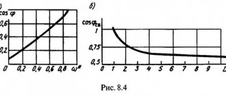
Transformer losses. The power P2 supplied by the transformer is less than that supplied by Ri since part of it is lost in the transformer during its operation. Losses in a transformer consist of losses in steel Rst and losses in copper Rm. Efficiency (Fig. 170) of the transformer
(] - = [Р 2 !(Р-г ' Р('т ¦ Рм)1 JUN %•
To reduce losses in steel due to eddy currents and hysteresis, transformer cores are made from sheet transformer steel containing up to 5% silicon.
The power loss in the copper windings depends on the load of the transformer: Ri - 1\GX 1\g.g. To reduce these losses, reduce the active resistance of the windings ru and r2 to a certain value,
increasing the cross-sectional area of the copper winding wire.
Losses in steel can be determined from the experience of no-load operation of a transformer at the rated primary voltage (D (Fig. 171, a). In this case, the useful power P2 = 0, and losses in the copper of the primary winding due to the low current can be ignored. Consequently, the power Rx » Rst,
Copper losses are determined from a short circuit experiment (Fig. 171, b), when the secondary winding terminals are closed to each other
Rice. 170. Dependence of transformer efficiency on load
Rice. 171. Schemes for determining losses in steel (a) and copper (b)
rotko, and such a low voltage (5-8% of the rated value) is supplied to the primary winding that the rated currents are established in the windings. Due to the low voltage, the magnetic induction and losses in the steel will be insignificant and the power
Rk * La-
The efficiency of the transformer depends on its load and reaches 98-99%.
⇐DC electric motors and their characteristics | Power supply devices and linear structures of automation, telemechanics and communications of railway transport | Autotransformers and saturation chokes⇒
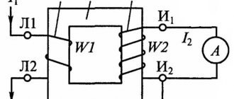
Determination of device currents
When determining the primary winding current, losses should be taken into account, as well as the magnetizing current of the transformer, the relative magnitude of which in low-power power transformers is very significant. The current values can be determined using the following formula:
It will be interesting➡ How does a power transformer work and where is it used?
where U1 and U2 are the voltages of the windings as specified;
P2 – power of the secondary winding as specified;
cos φ2 – load power factor according to the specification;
η – coefficient of performance (efficiency) of the transformer.
The choice of induction in the core rod and current density in the wires of the transformer windings - the permissible value of induction in the rod and yoke of the transformer core is determined by the selected value of the magnetizing current, power, frequency, type of transformer, number of joints in the core and the material of the latter.
You can read the article in more detail about the design of power transformers.
General structure and principle of operation
Let's consider the design of a simple transformer with two coils mounted on a closed magnetic circuit (see Fig. 2). The coil that receives current will be called the primary coil, and the output coil will be called the secondary coil.
Figure 2. Transformer design
Virtually all types of transformers use electromagnetic induction to convert the voltage entering the primary winding circuit. In this case, the output voltage is removed from the secondary windings. They differ only in shape, magnetic core materials and methods of winding the coils.
Ferromagnetic cores are used in low-frequency models. The following materials are used for such cores:
- steel;
- permalloy;
- ferrite.
In some high-frequency models, magnetic cores may be absent, and in some products materials made from high-frequency ferrite or alsifer are used.
Due to the fact that the characteristics of ferromagnets are characterized by nonlinear magnetization, the cores are assembled from sheet materials onto which windings are placed. Nonlinear inductance leads to hysteresis, to reduce which the method of lamination of magnetic circuits is used.
The core shape can be W-shaped or toroidal.
Figure 3. Transformer appearance
Basic principles of operation
When a sinusoidal current is supplied to the terminals of the primary windings, it creates an alternating magnetic field in the second coil that penetrates the magnetic circuit. In turn, a change in the magnetic flux provokes the induction of an emf in the coils. In this case, the magnitude of the EMF voltage in the windings is proportional to the number of turns and the frequency of the current. The ratio of the number of turns in the primary winding circuit to the number of turns of the secondary coil is called the transformation ratio: k = W1 / W2, where the symbols W1 and W2 indicate the number of turns in the coils.
If k > 1, then the transformer is step-up, and if 0 < k < 1, then the transformer is step-down. For example, when the number of turns that make up the primary winding is three times less than the number of secondary turns, then k = 1/3, then U2 = 1/3 U1.
Operating modes
The power transformer can operate in three modes:
- in idle state;
- in load mode;
- in short-circuited mode.
Since there is no current in the open circuit of the secondary winding, in this state no-load current circulates through the primary winding. The parameters of this current are used in efficiency calculations, the transformation ratio is determined, and losses in the core are found.
The main operating mode of the transformer is the state when the rated load is connected to its second winding. The primary current can be expressed through the resultant no-load current and the calculated load resistance current.
In short circuit mode of the secondary winding, all power is concentrated in the winding circuits. In this state, it is possible to determine the losses spent on heating the wires in the windings.
Transformer power circuits
The permissible current density in the wires of the transformer windings largely determines the weight and cost of the latter. The higher the current density in the windings, the lower their copper weight and, accordingly, the cost of the transformer. On the other hand, with increasing current density, losses in the copper of the windings and heating of the transformer increase.
Power supply diagram for a traction network of a 2×25 kV system using a three-phase transformer with step-up autotransformers.
The simplest is the power supply circuit for the traction network of a 2×25 kV system using a three-phase transformer and step-up autotransformers. A special feature of the circuit is that to increase the voltage to 55 kV, a conventional linear autotransformer AT is used, which is connected to the contact network and the supply wire, and transformer T is connected between the contact network and the rails.
Autotransformers are installed on the terminals of a 27.5 kV transformer or on the feeders of the contact network. The latter option is preferable, since it allows you to have only contact network buses at the substation, and autotransformers can be installed outside the territory of the traction substation.
In the scheme, a significantly larger part of the electricity is supplied to electric locomotives directly along the contact network - rails circuit, bypassing the step-up autotransformer.
This circumstance makes it possible to install step-up autotransformers at a substation of the same power as in the feeder zone, and not reserve them at the substation. When the autotransformer at the substation is disconnected, the autotransformer closest to the substation in the feeder zone takes on the role of step-up.
The principle of operation of a transformer.
The operating principle of the transformer is based on the phenomenon of electromagnetic induction
.
If alternating voltage U1
, then an alternating current
Io
an alternating magnetic field
around the winding and in the magnetic circuit .
The magnetic field forms a magnetic flux Фo
, which, passing through the magnetic circuit, crosses the turns of the primary and secondary windings and induces (induces) alternating emf in them -
e1
and
e2
.
And if a voltmeter is connected to the terminals of the secondary winding, it will show the presence of output voltage U2
, which will be approximately equal to the induced emf
e2
.
When a load, for example an incandescent lamp, is connected to the secondary winding, a current I1
F1
in the magnetic circuit , changing with the same frequency as the current
I1
.
Under the influence of an alternating magnetic flux, a current I2
, which in turn creates a counteracting magnetic flux
F2
, tending to demagnetize the magnetic flux generating it.
As a result of the demagnetizing effect of the F2
In the magnetic circuit, a magnetic flux
Фo
equal to the difference between the fluxes
Ф1
and
Ф2
and being part of the flux
Ф1
, i.e.
Resulting magnetic flux Фo
ensures the transfer of magnetic energy from the primary winding to the secondary and induces an electromotive force
e2
, under the influence of which current
I2
.
It is due to the presence of magnetic flux Фо
I2
exists , which will be greater the greater
Фо
.
But at the same time, the greater the current I2
, the greater the counteracting flow
F2
and, therefore, the less
Fo
.
From the above it follows that at certain values of magnetic flux F1
and the resistance
of the secondary winding
and
load
e2
, current
I2
and flux
Ф2
are set , ensuring the balance of magnetic fluxes in the magnetic circuit, expressed by the formula given above.
Thus, the flux difference Ф1
and
Ф2
cannot be equal to zero, since in this case there would be no main flow
Фo
Ф2
and current
I2
could not exist .
Consequently, the magnetic flux Ф1
, created by the primary current
I1
, is always greater than the magnetic flux
Ф2
, created by the secondary current
I2
.
The magnitude of the magnetic flux depends on the current creating it and on the number of turns of the winding through which it passes.
The voltage of the secondary winding depends on the ratio of the number of turns in the windings
.
With the same number of turns, the voltage on the secondary winding will be approximately equal to the voltage supplied to the primary winding, and such a transformer is called an isolation
.
If the secondary winding contains more turns than the primary, then the voltage developed in it will be greater than the voltage supplied to the primary winding, and such a transformer is called a step-up
.
If the secondary winding contains fewer turns than the primary, then its voltage will be less than the voltage supplied to the primary winding, and such a transformer is called a step-down
.
Hence. By selecting the number of turns of the windings, at a given input voltage U1
obtain the desired output voltage
U2
. To do this, they use special methods for calculating the parameters of transformers, with the help of which the windings are calculated, the cross-section of the wires is selected, the number of turns is determined, as well as the thickness and type of the magnetic core.
The transformer can only operate in alternating current circuits. If its primary winding is connected to a direct current source, then a magnetic flux is formed in the magnetic circuit, constant in time, in magnitude and direction. In this case, an alternating voltage will not be induced in the primary and secondary windings, and therefore, electrical energy will not be transferred from the primary circuit to the secondary. However, if a pulsating current flows in the primary winding of the transformer, then an alternating voltage will be induced in the secondary winding, the frequency of which will be equal to the ripple frequency of the current in the primary winding.
How to increase energy transfer
It is possible to increase the transmission of electricity along the supply wire-rail circuit by installing special step-up autotransformers at substations, the power of which corresponds to the load of the substation power arm, or by specially connecting two standard three-phase transformers at the substation.
The U/D-1 connection group of the second transformer is obtained by the same double relabeling of the terminals of the two phases of the primary and traction windings of the standard transformer. The designation of the secondary winding terminals according to the factory markings is shown in the figure with the index “T”.
The same terminal of the traction winding of both transformers is connected to the rails, as in the 25 kV system (terminal st according to the factory marking). The connection with the st output rails determines that the windings on the middle rod will be the least loaded for both transformers.
By analogy with three-phase transformers in a 25 kV system, if a wire is connected to terminal at, we have a positive voltage of this wire relative to the rails, and to terminal bm, we have a negative voltage of the wire relative to the rails.
Power supply diagram for the traction network of a 2×25 kV system with a series connection of two phases of three-phase transformers (a), vector diagrams of the voltages of the primary and secondary windings (b).
The first transformer is connected by its terminal am to the contact network of the first feeder zone, and by its terminal bm to the contact network of the second feeder zone.
The second transformer has a reverse connection: with its terminal yat it is connected to the supply wire of the second feeder zone, and with its terminal bm - to the supply wire of the first feeder zone.
The sequential connection of two secondary windings of transformers with winding connection groups U/D-11 and U/D-1 makes it possible to obtain double the voltage of the two phases supplying the traction network on opposite sides of the substation.
It will be interesting➡ Oil transformers - what they are, device and principle of operation
As above, at the contact network and the supply wire, and the voltages of the supply line are indicated, with which the voltage of the contact network and the supply wire coincide in phase. The latter are shifted by 180°. Therefore, the figure shows the position of only the contact line-rail voltages. It does not differ from the position of these vectors in a 25 kV system, if in a 2x25 kV system the transformer connected to the contact network is connected to the same phases of the supply line as in the 25 kV system.
Types of magnetic cores
Based on the design of the magnetic circuit, transformers are divided into rod and armored.
| Figure 1. Design of single-phase rod (a) and armored (b) transformers |
A single-phase transformer of an armored design (Figure 1, b) has one rod with windings and a developed yoke, which partially covers the windings like “armor”.
To convert, or transform, three-phase current, you can use three single-phase transformers (Figure 2), the windings of which are connected in a star or delta circuit and connected to a three-phase network. Such a device is called a three-phase transformer group or group transformer. More often, however, three-phase transformers with a common magnetic core for all phases are used, since such transformers are more compact and cheaper.
| Figure 2. Three-phase transformer group | Figure 3. The idea of forming a three-phase three-leg transformer |
The idea of forming a three-phase rod-type transformer is shown in Figure 3. If the condition is met for three-phase sinusoidal currents
ia + ib + ic = 0,
then for the sinusoidal flows of three transformers (Figure 3, a) the condition is also met
Фa + Фb + Фc = 0
Therefore, if you combine three rods 1, 2 and 3 (Figure 3, a) into a common rod, then the flow in this rod will be zero and this rod can be removed. Then we get a three-phase three-rod transformer, shown in Figure 3, b. The design of this transformer can be simplified by placing all three rods in the same plane (Figure 3, c). This last design was proposed by M. O. Dolivo-Dobrovolsky in 1889 and became widespread. Such a magnetic circuit is not completely symmetrical, since the length of the magnetic lines of the middle phase is somewhat shorter than for the outer ones, but the influence of this asymmetry is very insignificant.
A three-phase armor transformer (Figure 4) can be considered as three single-phase armor transformers placed next to or on top of each other. In this case, the middle phase has a reverse inclusion relative to the outer ones, so that in the contacting parts of the magnetic system the phase fluxes are added and not subtracted. Because
| Figure 4. Design of a three-phase armored transformer |
In armored transformers, the coefficient of electromagnetic coupling between the windings is somewhat higher than in rod transformers, and therefore armored transformers are somewhat more advanced in electromagnetic terms. However, this advantage is not significant. Since armored transformers are more complex in design, armored power transformers are not built in Russia.
As the power of transformers increases, their size and difficulty of transportation by rail increase. Therefore, in transformers with a power Sn > 80 - 100 MV×A per phase and a voltage of 220 - 500 kV, an armored rod or multi-rod design is used. Such designs are obtained if, for transformers of the type shown in Figures 1, a and 3, one side yoke is added to the left and right (Figure 5). In this case, the magnetic flux in the upper and lower yokes branches out and in the case shown in Figure 5, a, decreases by half, and in the case in Figure 5, b - by a factor of 1, a and 3, c. The cross-section of the yoke can be reduced by the same amount, as a result of which the height of the magnetic cores decreases.
Figure 5. Design of armored rod transformers
Three-phase transformers with a common magnetic system are predominantly used. Three-phase groups of single-phase transformers are used, firstly, at very high powers (Sн > 300 MV×A), when transport of a three-phase transformer becomes very difficult or impossible, and, secondly, sometimes at Sn > 30 MV×A, when the use single-phase transformers allows you to reduce reserve power in case of an accident or repair.
| Figure 6. Schemes of butt magnetic cores |
| Figure 7. Laying steel sheets in layers of laminated magnetic cores of single-phase (a) and three-phase (b) transformers |
Scheme of operation when one of the transformers is disconnected
In the event that a transformer connected to the supply wire buses is disconnected at the substation, we will have the circuit practically considered in the figure with step-up autotransformers, the role of which is played by the autotransformers closest to the substation in the feeder zones.
At the same time, in the sections from the substation to the autotransformers closest to it we have a 25 kV system, and in most of both feeder zones the 2x25 kV system remains. Since the resistance of sections with a 25 kV system is greater than their resistance with a 2x25 kV system, neighboring substations take on a greater load.
If a transformer connected to the contact network buses is disconnected at a substation, the autotransformers closest to the substation will operate in transformer mode and, with significant traffic volumes or heavy trains, may be overloaded.
Scheme of operation when one of the transformers is turned off.
This can be avoided either by switching to one-way power supply to feeder zones from neighboring substations during the shutdown of the specified transformer, or by bringing the connection group of an operational transformer into correspondence with the group of the disconnected transformer and connecting it to the contact network buses.
To do this, it should be possible to quickly switch two phases on the primary side of the transformer connected in normal mode to the supply wire buses.
If it is necessary to have a greater degree of redundancy of transformers, it is possible, as in the case of single-phase transformers, to use a third three-phase transformer as a backup with the ability to connect it to the 110 (220) kV buses and to the buses of the contact network or supply wire instead of any transformer taken out of operation.
The considered schemes of substations with three-phase transformers are promising on the roads of the CIS countries at the junction of 25 and 2×25 kV systems and at traction substations, if necessary, to power a large regional load from them, as well as when strengthening the power supply system of previously electrified lines.
Detailed working principle of 3 phase transformer
Three-phase current can be transformed by three completely separate single-phase transformers. In this case, the windings of all three phases are not magnetically connected to each other: each phase has its own magnetic circuit. But the same three-phase current can be transformed by one three-phase transformer, in which the windings of all three phases are magnetically connected to each other, since they have a common magnetic circuit.
To understand the principle of operation and structure of a three-phase transformer, let’s imagine three single-phase transformers placed one next to the other so that their three rods form one common central rod (Fig. 1). On each of the other three rods, primary and secondary windings are superimposed (the secondary windings are not shown in Fig. 1).
Let us assume that the primary coils of all transformer bars are exactly the same and wound in the same direction (in Fig. 1 the primary coils are wound clockwise when viewed from above). We connect all the upper ends of the coils to neutral O, and connect the lower ends of the coils to the three terminals of the three-phase network.
The currents in the transformer coils will create time-varying magnetic fluxes, which will each be closed in its own magnetic circuit. In the central composite rod, the magnetic fluxes will add up and give a total of zero, because these fluxes are created by symmetrical three-phase currents, regarding which we know that the sum of their instantaneous values is equal to zero at any moment of time.
For example, if the current I in the AX coil was greatest and passed in the direction indicated in Fig. 1 direction, then the magnetic flux would be equal to its greatest value Ф and would be directed in the central composite rod from top to bottom. In the other two coils BY and CZ, the currents I2 and I3 at the same moment in time are equal to half the highest current and have the opposite direction with respect to the current in the AX coil (this is the property of three-phase currents). For this reason, in the rods of the BY and CZ coils, the magnetic currents will be equal to half the highest flux and in the central composite rod will have the opposite direction with respect to the flux of the AX coil. The sum of the flows at the moment under consideration is zero. The same is true for any other moment.
The absence of flow in the central rod does not mean the absence of flows in the remaining rods. If we destroyed the central rod, and the upper and lower yokes were connected into common yokes (see Fig. 2), then the flux of the AX coil would find its way through the cores of the BY and CZ coils, and the magnetomotive forces of these coils would add up to the magnetomotive force of the coil OH. In this case, we would get a three-phase transformer with a common magnetic circuit of all three phases.
Since the currents in the coils are shifted in phase by 1/3 of a period, the magnetic fluxes they create are also shifted in time by 1/3 of a period, i.e., the highest values of magnetic fluxes in the coil rods follow each other after 1/3 of a period .
A consequence of the phase shift of the magnetic fluxes in the cores by 1/3 of the period is the same phase shift of the electromotive forces induced in both the primary and secondary coils superimposed on the rods. The electromotive forces of the primary coils almost balance the applied three-phase voltage. The electromotive forces of the secondary coils, when the ends of the coils are correctly connected, produce a three-phase secondary voltage, which is supplied to the secondary circuit.
How are the beginnings of the primary winding of a three-phase transformer designated?
All the beginnings of the primary windings of a three-phase transformer are designated in capital letters: A, B, C; the beginning of the secondary windings - in small letters: a, b, c. The ends of the windings are designated respectively: X, Y, Z and x, y, z. The terminal of the output zero point when connected by a star is designated by the letter O.
A, B, C - indicate the beginning of the higher voltage windings, and the letters X, Y and Z indicate the end of these windings.
Transformers with a “zero point” have a lead-out terminal marked with a large letter O.
The ends of the low voltage windings are designated in the same way, but lowercase letters x, y, z are used for this - this is the end of the phase windings, and a, b, c are their beginning.
Star and delta are the main ways to connect the windings of a 3-phase transformer.
By connecting the free terminals of the three windings to each other, their beginnings or ends form a neutral point. The remaining free terminals are connected to the three-phase load or the input voltage going to the transformer from the power line.
Star connection of transformer windings
The connection of windings in a triangle occurs according to the principle of serial connection, when the end of one winding is connected to the beginning of another, and the end of the second winding is connected to the beginning of the third winding.
triangle connection
Winding connection points connect external devices. Designation of the terminals of a three-phase transformer and their connection diagram.
∆ - connection of the transformer windings with a triangle.
Y – star connection of the transformer windings.
designation of three-phase transformers
The connection of windings below the line indicates windings of low voltage, and above the line of higher voltage.
The number indicates the angle between the EMF vectors with 30° degrees of angular units.
The decoding of the designation indicates that the windings of the higher voltage in the first case are connected by a star, and the windings of the lower voltage are also connected by a star. In this case, the low voltage windings have a connected “0” point.
How many rods should a three-phase transformer have?
Three-phase transformers are used to power three-phase or two-phase networks having either a common three-phase magnetic core or two or three separate core-type magnetic cores.
According to the assembly method in modern designs for both single-phase and three-phase magnetic cores, laminated types have become predominant, as they are more reliable in operation, convenient to manufacture, and require less complex equipment and devices for assembly.
Application area
These devices are designed to convert the operational parameters of three-phase electrical networks and are used in the following types of power systems:
- electricity transportation and distribution systems;
- converting devices;
- electrical technological installations (welding equipment, electric furnaces, etc.);
- communication and telemechanics devices;
- automation systems;
- household electrical equipment;
- electrical measuring devices.
A suitable connection diagram is determined in accordance with the operating conditions of the device, which include network power, voltage level, and load asymmetry. The choice of connection scheme is also influenced by economic considerations.
Checking the device
The belonging of a transformer to one or another connection group can be determined using a polarometer-voltmeter of the magnetoelectric system with zero in the middle of the scale and the polarity of its terminals marked.
Each group of connections corresponds to a specific table of polarometer needle deviations for the transformer under test and, after comparing it with the existing ones, a group of winding connections is established.
When the HV windings are switched on to a constant voltage of a certain polarity, an instantaneous EMF is induced in the other windings of the transformer at the moment of switching on, the magnitude and direction of which depend on the group of connections of the windings and are recorded using a polarometer.
The video below discusses in detail the operating principle of a three-phase transformer and its structure.
Definitions
Medium power three-phase power transformer - no more than 33.3 MVA with a short-circuit impedance not higher than 25 - 0.3N/W%. N is the rated power of the transformer (MVA), W is the number of core bars.
Large three-phase power transformer - power up to 100 MVA, with an impedance higher than that determined by the formula specified for the previous class of products.
Distribution three-phase transformer - step-down, power up to 2.5 MVA, with separate windings and ON type cooling.