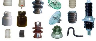
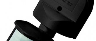
What are electrical insulators?
Electrical insulators are a dielectric element of an electrical installation, structurally made of insulating material and reinforcing parts. The dielectric is intended for electrical separation, and metal structures make it possible to fix both the insulator itself and the conductors on it. Glass, polymer or ceramics are used as dielectric materials.
Purpose
Electrical insulators are designed for fastening busbars, wires, trawls and other current-carrying elements to the body of an electrical installation, support consoles and other structures. In addition, they insulate conductors when passing through walls, allow you to separate electrical installations from each other and other load-bearing functions.
Depending on the installation location, they are divided into internal and external. Also of no small importance is the voltage class for which a particular insulator is designed. Because of this, its design and certain technical characteristics will differ, determining the possibility of their use in certain electrical installations [ ].
Main technical characteristics
In accordance with the requirements of regulatory documents, the following characteristics are regulated for electrical insulators:
- Dry-discharge voltage is the value at which an electrical discharge will occur under dry surface conditions.
Insulator overlap - Wet discharge voltage – determines the same value as the previous parameter, but subject to rain falling on the surface. In this case, an option is considered when the direction of the jets is located at an angle of 45°.
Rice.
2. Insulator in the rain With such a flow of jets at an angle of 45°, which are indicated in Figure 2 by the letter A, maximum flow around surface B is ensured, and, as a result, minimum resistance to electric current is provided - from 9.5 to 10.5 kOhm*cm . This parameter is always below the dry discharge.
- Breakdown voltage is the value at which a breakdown occurs between two poles. Depending on the design, the poles can be represented by a rod and a cap or a busbar and a flange.
- Mechanical strength - checked by the load on bending, tearing or shearing of the head. In this case, the structure is rigidly fixed and a force is applied to it, gradually increasing to such a level of the highest stress in the material that leads to destruction.
- Thermal stability - tested by alternating heating and sudden cooling. Consists of two or three cycles, depending on the material and design. After which an electrical potential is applied, creating multiple discharges.
Checking technical specifications.
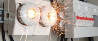
It should be noted that test procedures are not mandatory for all insulators produced at the plant. Only 0.5% of the batch is exposed to electrical, thermal and mechanical stress. It is mandatory for all insulators to test the flashover voltage for three minutes, at which spark discharges occur on the insulator.
The mechanical characteristics of suspended insulators must be checked. To do this, a mechanical load is applied to it within a minute, which is regulated by factory or state standards.
Such tests ensure normal operation of electrical insulators at rated currents and rated voltages in the network. And also, a sufficient level of reliability. In addition, some models are subject to periodic inspection during operation. Based on the results of periodic inspections and tests, they can be cleaned, rejected and replaced.
4.2. Reliability requirements
4.2.1. The reliability of an insulator is determined by the average annual failure rate, the probability of failure-free operation and the gamma-percentage service life.
A failure in normal operating mode is considered to be the destruction of an insulator or a decrease in its electrical parameters, leading to flashover at operating voltage.
The average annual failure rate is selected from the following range: 0.000005, 0.00001, 0.00005, 0.0001.
The normalized value of the average annual failure rate must be indicated in the technical specifications for a specific type of insulator.
The probability of failure-free operation P is calculated using the formula
P
(
t
) = l —
At
, (1)
where t is the time since the start of operation, year;
A is the average annual failure rate, 1/year.
4.2.2 The gamma-percentage service life of insulators with a probability of 0.999 must be at least 30 years.
Typical design
First, let's look at an example of a typical design using a sketch of a pin insulator.
Rice. 3. Sectional view of insulator
As you can see in Figure 3, the design includes ribs A and B. Which allow you to increase the electrical strength by lengthening the path for leakage current along the surface. Due to the different slope angles of the ribs, protection from precipitation is possible. So ribs A have a smaller slope, so they are most relevant for solid precipitation - snow, mud, etc. Because moisture can sneak underneath and significantly reduce the discharge voltage.
Unlike them, skirts B allow you to completely eliminate the possibility of moisture ingress in rainy weather. This provides a constant supply of resistance, which guarantees the breakdown voltage. In addition, skirts B are not afraid of ice freezing and can ensure normal operation of high-voltage lines in the event of a difficult meteorological situation.
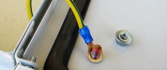
To fasten the head of the rod, a B thread is provided, which allows you to secure the structure to the console or reinforcing hooks. In the upper part there is a groove G for fixing the wire. Additionally, the wire is tied with wire for more reliable fastening of overhead power lines.
Rice. 4. Bushing design
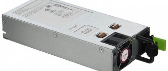
The bushing insulator has a slightly different design, since its task is not only to isolate the current-carrying busbar from the wall, but also to ensure the normal flow of current inside the insulator itself. Look, the tire is crimped on both sides with an aluminum cap to secure it securely on the outside. Inside, mechanical fastening is carried out using a sealant, which in addition prevents the entry of pollutants and aggressive substances. Also, for the convenience of attaching wires or busbars, an additional petal can be installed on the cover itself, as shown in Figure 4.
A protective shell made of silicone rubber prevents electrical breakdown along the surface from the tire to the flange. Insulation against breakdown of internal elements is carried out using a fiberglass pipe, which is placed inside a ribbed jacket. More detailed information about the parameters can be obtained from the model designation.
6.2. Acceptance tests
6.2.1. Acceptance tests are carried out according to the indicators, in the sequence and volume specified in tables 4 and 5.
Table 4
| Indicator name | Item number | Sample size | |
| Technical requirements | Test methods | ||
| 1 Surface quality of the insulating part | 4.3.1 | 7.2 | 100% |
| 2 No internal defects in the insulating part | |||
| 3 Availability of reinforcing ligament seam coating | 4.1.9 | ||
| 4 Mechanical tensile force for 1 min | 4.1.3 | 7.3 | |
| 5 Deviations from nominal dimensions | 3.5 | 7.2 | According to table 5 |
| 6 Heat resistance | 4.1.4 | 7.7 | |
| 7 Breaking mechanical tensile force | 4.1.2 | 7.6 | |
| 8 No open porosity | 4.3.1 | 7.11 | 3 pieces from ceramic part |
| 9 Quality of zinc coating | 4.3.3 | 7.9 | According to table 5 |
Table 5
In pieces
| Lot size N | Sample size |
| Up to 100 incl. | 3 |
| From 101 to 500 incl. | 5 |
| Over 500 | |
| Note - If the calculation does not yield an integer, then select the next integer. | |
6.2.2. Tests according to points 1-4 of Table 4 are carried out according to a continuous control plan.
Insulators that do not meet one of the indicators are rejected.
6.2.3. Tests according to points 5-9 of Table 4 are carried out according to a sampling plan. During random control, the sample is completed using the random selection method in accordance with GOST 18321.
Upon receipt of satisfactory test results on all insulators of the first sample, the batch is accepted.
If unsatisfactory test results are obtained on two or more insulators of the first sample, the batch is rejected.
If unsatisfactory test results are obtained on one insulator of the first sample, repeated tests are carried out on a double sample of insulators selected from the same batch. Upon receipt of satisfactory test results on all insulators of the second sample, the batch is accepted.
If unsatisfactory test results are obtained on at least one insulator of the second sample, the batch is rejected.
Designations of insulators
The labeling of each product contains information about its type, material and other characteristics. Look at an example of marking for insulator NSPKr 120 - 3/0.6 - B.
- The first letter N indicates the purpose of the model, in this case N - tension. It can also be K - console, F - fixed, P - suspended.
- C - indicates that this is a rod insulator.
- P is an insulating material, in this case P is a polymer.
- K – outer coating, in this case silicone rubber.
- p – index indicating that the protective shell is ribbed and solid.
- 120 is an indicator of the normalized breaking force in kN.
- 3 – voltage class of overhead line wires for which it is used.
- 0.6 – indicates the length of the leakage current path, measured in meters.
- B - indicates the type of engagement.
4.5. Marking
4.5.1. Marking of insulators is in accordance with GOST 18620 with the following data:
symbol of the insulator type (without indicating the technical specifications number);
— month and year of manufacture;
— trademark of the manufacturer.
The location and method of marking must be indicated in the design documentation for the specific type of insulator.
4.5.2. Transport marking - in accordance with GOST 14192 with the application of the handling mark “Fragile. Carefully".
Classification
To ensure reliable power supply and maintain the maximum level of safety in each specific case, insulators of the appropriate type and design must be used in electrical installations. Depending on the criterion, several parameters of their classification are distinguished.
By purpose
Depending on the purpose, the following types of insulators are distinguished:
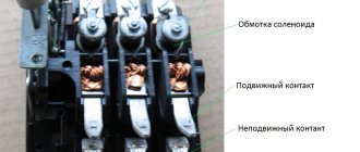
- Stationary – used for mechanical fastening of current-carrying rods or busbars in switchgears. Depending on their purpose, stationary insulators are further divided into support and bushings. Thus, support insulators act as a base on which busbars are attached in cells or supporting structures. Bushings allow you to pass a current-carrying element through a wall or ceiling of a room.
- Hardware - have a similar purpose to stationary ones, but in relation to any devices. For example, hardware insulators are widely used in rectifier installations, power devices, complete substations, installations of high-voltage devices and other units. Look at Figure 5 for an example of its use, where it is designated AI.
Rice. 5. Example of hardware isolators - Linear – used for external installation under high-voltage lines or busbars of open switchgears. A distinctive feature of linear insulators is the presence of wide ribs or skirts designed to increase the path of surface breakdown in the event of precipitation.
According to the material of execution
Depending on the dielectric used, the following types of insulators are distinguished:
- With a porcelain body - they have high mechanical compressive strength, but are afraid of dynamic influences. To prevent the appearance of conductive channels due to the deposition of dust and dirt on the surface, the ceramic material is coated with glaze.
- Polymer insulators are divided into models that have elastic deformation and monolithic ones. They have a much higher resistivity of the material than porcelain. But the soft surface is more susceptible to contamination than glazed porcelain. In addition, due to exposure to ultraviolet radiation, the polymer deteriorates and loses its properties, so they are used for indoor installation.
- Glass electrical insulators are not as durable and are susceptible to chipping under dynamic influences. But unlike other materials, they are not exposed to aggressive reagents. They are lighter in weight and easier to maintain than porcelain.
According to the method of mounting on the support
Depending on the method of fastening there are:
Classification by mounting method
- Pin type (a) – they are attached using metal reinforcement and act as a support for overhead power lines, which is where the name post-pin insulators comes from.
- Suspended (b) - made with disc insulators, which are assembled into garlands, depending on the voltage class of the electrical devices connected to them.
- Rod (c) - have the form of a solid rod, which is installed as a support or suspended from reinforcement elements as a tension rod. Post-rod insulators are installed in switchgears for busbar insulation. Current-carrying parts are attached to their edges using cast-iron wings.
6.3. Periodic testing
6.3.1. Periodic tests are carried out at least once every five years according to the indicators, sequence and scope specified in Table 6.
For the first time, periodic tests are carried out no later than two years after the start of production of insulators.
6.3.2. Tests are carried out according to a sampling plan. The sample is completed by random selection in accordance with GOST 18321 from a batch that has passed acceptance tests.
6.3.3. Insulators are considered to have passed the tests if satisfactory test results are obtained for all indicators.
If one defective insulator is detected according to one of the indicators, repeat control is carried out on twice the number of insulators according to the indicator for which an unsatisfactory result was obtained.
If unsatisfactory results of repeated tests are obtained on at least one insulator, the acceptance and shipment of insulators is suspended until the causes are identified and eliminated and satisfactory test results are obtained.
Table 6
| Indicator name | Item number | Type of test | Sample size, pcs. | Test sequence | ||
| Technical requirements | Test methods | Periodic | Typical | |||
| 1. Surface quality of the insulating part | 4.3.1 | 7.2 | X | X | 16 | Passed acceptance tests |
| 2. Deviations from nominal dimensions | 3.5 | 7.2 | X | X | 16 | Tested according to point 1 |
| 3. Creepage distance | 3.6 | 7.4 | X | X | 16 | Tested according to point 2 |
| 4. Impact of single blows | 7.12 | X | X | 4 | Tested according to point 3 | |
| 5. Destructive mechanical tensile force | 4.1.2 | 7.6 | X | X | 12 | Tested according to points 3, 4, 14 |
| 6. Heat resistance | 4.1.4 | 7.7 | X | X | 4 | Tested according to point 3 |
| 7. Breaking bending moment* | 4.1.2 | 7.6 | X | X | 4 | Tested according to point 6 |
| 8. No open porosity | 4.3.1 | 7.11 | X | X | Pieces of ceramic part | |
| 9. Short-term (one minute) power frequency voltage in dry condition | 4.1.6 | 7.1 | — | X | 4 | Tested according to point 3 |
| 10. Short-term (one minute) power frequency voltage in the rain | 4.1.6 | 7.1 | — | X | 4 | Tested according to point 9 |
| 11. Lightning impulse withstand voltage | 4.1.6 | 7.1 | — | X | 4 | Tested according to point 10 |
| 12 Power frequency withstand voltage in dirty and wet conditions | 4.1.6 | 7.10 | — | X | 4 | Tested according to point 11 |
| 13 Radio interference level | 4.1.7 | 7.5 | — | X | 4 | Tested according to point 12 |
| 14 Thermomechanical strength | 4.1.5 | 7.8 | X | X | 4 | Tested according to point 13 |
| 15 Durability during transportation | 8.1 | 7.2 | — | X | After packing | |
| * Insulators with a spherical hinge joint after testing for heat resistance are tested according to point 5. Note - The sign “x” means that the tests are carried out, the sign “-” means that they are not carried out. | ||||||