The concept of ideal capacity
The ideal capacitance in electrical circuits is a capacitor. The capacitor and inductor do not consume power, they have \(P=0.\) That is, in these elements there is no irreversible transformation of energy into its other types, the available energy circulates in them. In other words, electricity is stored in the magnetic field of the coil and the electric field of the capacitor. This process takes about a quarter of a period, after which it is sent back into the circuit.
Definition 3
Due to the processes occurring in the coil and capacitor, they are called reactive elements. Accordingly, their resistances are called reactive. But the resistor has active resistance.
When exchanging energy, the intensity characterizes the maximum value of the rate of energy flow into the magnetic field of the coil and the maximum value of the rate of energy flow into the electric field of the capacitor. This intensity is reactive power and is calculated as follows:
\(Q=UIsinφ\)
When the load is on the inductance \(φ≥0\), the reactive power takes only positive values. In the case of leading load current, the capacitances are negative.
The reactive power of an ideal coil corresponds to the highest value of the energy reserve in the coil and the frequency.
Definition 4
Power factor is the ratio of apparent and active power. Its value is defined as the cosine of the displacement angle between current and voltage
Along with total and active power, there is the concept of complex power. Reactive power is a characteristic of the circulation of energy between a source and a receiver. The reactive current does not produce any work and this entails losses in power plants, and accordingly an increase in power. Therefore, today there is a tendency to increase the power of electrical networks.
Some power receivers, such as motors, use active-inductive loads. If a capacitor is connected to this load, the total receiver current will reach the value of the voltage phase. That is, it will increase, but its overall value will fall at constant active power. All this entails losses in the total current of the circuit. Capacitors are used to increase power.
Is it difficult to figure it out on your own?
Try asking your teachers for help
Solving problems Tests Essays
Instantaneous power
To instantly determine the power in an electrical circuit, enter a formula in the form:
Are you an expert in this subject area? We invite you to become the author of the Directory Working Conditions
$p = ui$
Instantaneous power has two types of elements:
- constant component;
- harmonic component.
Instantaneous power has an angular frequency that is twice the angular frequency of voltage and current. At negative values of instantaneous power, energy will be returned to the power source. This suggests that the directions of voltage and current have opposite values in a two-terminal network.
Such a return of energy to the source occurs due to the fact that there is an energy reserve in electric and magnetic fields at the level of capacitive and inductive elements. They are part of a two-terminal network.
Definition 2
Active power is the average value of instantaneous power over a certain period of time.
$P = UI cos \phi$
Active power when consumed by a passive two-terminal network does not have negative values. At the input of a passive two-terminal network, $cos \phi \geq 0$ will be fixed. The situation in which $P=0$ is possible in theory, but only for a two-terminal network without active resistances. It should contain:
Finished works on a similar topic
Course work Capacity and power of an electrical circuit 490 ₽ Abstract Capacity and power of an electrical circuit 260 ₽ Test work Capacity and power of an electrical circuit 240 ₽
Receive completed work or specialist advice on your educational project Find out the cost
- capacitive elements;
- ideal inductive elements.
Fig.1.48
[/td]
where is the current amplitude,
- initial phase.
The phase shift between voltage and current in a circuit with a capacitance is equal to i.e. the current in a circuit with a capacitor is 90° ahead of the applied voltage in phase (Fig. 1.49).
Complex resistance of a circuit with capacitance
§53. Capacitance in AC circuit
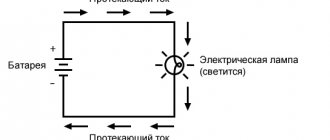
Current and voltage. In a direct current circuit, a capacitance (an ideal capacitor) has an infinitely large resistance, since after the charging process is completed, such a capacitor does not pass electric current. However, when the capacitance is connected to an alternating current source (Fig. 191,a), a continuous process of charging and discharging occurs, while alternating current passes through the capacitance.
The current i when a capacitance is connected to an alternating current circuit is determined by the amount of electricity q passing through this circuit per unit time. Hence,
i = ?q / ?t
where ?q is the change in the amount of electricity (charge q) over time ?t.
The amount of electricity q accumulated in the capacitor when the voltage changes and also changes continuously. Therefore, taking into account formula (69), we will have:
i = C ?u / ?t
where ?u is the change in voltage and over time ?t.
From Fig. 191b it is clear that the rate of change of voltage ?u/?t will be greatest at times when the angle ?t is equal to 0; 180 and 360°. Consequently, at these instants of time the current i has a maximum value. At moments of time when the angle ?t is equal to 90° and 270°, the rate of change of voltage ?u/?t = 0 and therefore i = 0.
During the first quarter of the period, the capacitance is charged and a charge current flows in the circuit, which we consider positive. In this case, as the capacitance is charged and the potential difference across the electrodes increases, the current i decreases. At ?t = 90° the capacitance is fully charged, the potential difference at the electrodes becomes equal to the source voltage and the current i = 0.
In the second quarter of the period, the capacitance begins to discharge and the current i changes its direction (becomes negative). At
Rice. 191. Scheme of connecting a capacitance to an alternating current circuit (a), curves of current i voltage u (b) and vector diagram (c)
?t =180°, when u = 0, the i-discharge current reaches its maximum value. At this moment, the polarity of the voltage and source changes and the process of recharging the capacitance begins with the opposite (negative) direction of current i. At co/ = 270°, the charge stops, the current i becomes zero and the discharge begins with the initial (positive) direction of the current.
Thus, the capacitance is charged twice and discharged twice during one period of voltage change. Consequently, alternating current i continuously flows in the circuit (see Fig. 191, a). From Fig. 191, b it is clear that when a capacitance is connected to an alternating current circuit, current i leads the voltage in phase by an angle of 90°, or that the voltage lags in phase from current i by an angle of 90° (Fig. 191, c).
Capacitance. The resistance that capacitance provides to alternating current is called capacitive. It is designated Xc and measured in ohms. Physically, capacitance is due to the action of e. d.s. es arising in capacitor C. This e. d.s. is directed against the applied voltage u, since a charged capacitor can be considered as a source with some e. d.s. es acting between its plates. Therefore e. d.s. ec prevents the current from changing under the influence of voltage u, i.e., it provides a certain resistance to the passage of alternating current.
From formula (70) it follows that the greater the capacitance C and the rate of change of voltage ?u/?t, i.e. the frequency of its change f (value ?), the greater the current i in the circuit with the capacitance and the lower the capacitance:
Xс = 1 /(?C)
Ohm's law for a circuit with capacitance:
I = U / Xс = U / ( 1 /(?C) )
Electric power. Let's consider how electrical power changes in an alternating current circuit with a capacitance. It can be obtained graphically by multiplying the ordinates of the current and voltage curves at different angles ?t. The instantaneous power curve (see Fig. 179,b) is a sinusoid that changes at double frequency 2? compared to the frequency of changes in current i and voltage u. Consequently, in this circuit there is also a continuous oscillatory process of energy exchange between the source and the capacitance. In the first and third quarters of the period, the power is positive, that is, the capacitor receives energy W from the source and accumulates it in its electric field. In the second and fourth quarter of the period, the capacitor releases the accumulated energy to the source (power is negative); in this case, the flow of current through the circuit is maintained by e. d.s. es. In general, no electrical energy enters the capacitive reactance during the period (the average power value over the period is zero). Therefore, capacitive reactance, as well as inductive reactance, belongs to the group of reactances.
To characterize the process of energy exchange between the source and the tank, the concept of reactive power of the tank is introduced:
Qс = UсI
where Uc is the voltage applied to the capacitor (rms value).
This power can also be expressed in the form
Qс = U2с/ Xс or Qс = I2Xс
It should be noted that in real capacitors there are power losses, as a result of which they consume some electrical energy from the source. Power losses are caused by the fact that in the dielectric separating the plates of the capacitor, under the influence of an alternating electric field, bias currents arise, heating the dielectric. The greater the voltage and the frequency of its change, the greater the power loss in the capacitors from bias currents. However, these losses are significant only in capacitors used in high-frequency installations. At a standard frequency of 50 Hz, capacitor losses are so small that they are usually ignored.
INFOFIZ
Let us consider separately the cases of connecting an external alternating current source to a resistor with resistance R
, capacitor capacitance
C
and inductor
L. In all three cases, the voltages across the resistor, capacitor and coil are equal to the voltage of the AC source.
1. Resistor in AC circuit
Resistance R is called active because a circuit with such resistance absorbs energy.
Active resistance is a device in which the energy of electric current is irreversibly converted into other types of energy (internal, mechanical)
Let the voltage in the circuit change according to the law: u = Umcos ωt,
then the current strength changes according to the law: i = u/R = IRcosωt
u – instantaneous voltage value;
i – instantaneous current value;
IR
is the amplitude of the current flowing through the resistor.
The relationship between the amplitudes of current and voltage across a resistor is expressed by the relation RIR
=
UR
Current fluctuations are in phase with voltage fluctuations. (i.e. the phase shift between the current and voltage across the resistor is zero).
2. Capacitor in AC circuit
When a capacitor is connected to a DC voltage circuit, the current is zero, and when a capacitor is connected to an AC voltage circuit, the current is not zero. Therefore, a capacitor in an AC voltage circuit creates less resistance than in a DC circuit.
Relation between current amplitudes IC
and voltage
U.C.
:
The current is ahead of the voltage in phase by an angle of π/2.
3. Coil in AC circuit
In a coil connected to an alternating voltage circuit, the current strength is less than the current strength in a constant voltage circuit for the same coil. Consequently, the coil in an alternating voltage circuit creates more resistance than in a direct voltage circuit.
Relation between current amplitudes IL
and voltage
UL
:
ω LIL
=
UL
The current is out of phase with the voltage by an angle of π/2.
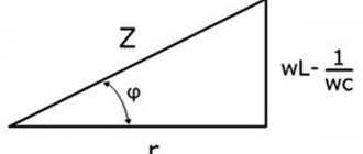
Now we can construct a vector diagram for a series RLC circuit in which forced oscillations occur at frequency ω. Since the current flowing through series-connected sections of the circuit is the same, it is convenient to construct a vector diagram relative to the vector representing current oscillations in the circuit. We denote the current amplitude by I
0. The current phase is assumed to be zero. This is quite acceptable, since it is not the absolute phase values that are of physical interest, but the relative phase shifts.
The vector diagram in the figure is constructed for the case when or In this case, the voltage of the external source is ahead in phase of the current flowing in the circuit by a certain angle φ.
Vector diagram for a serial RLC circuit
From the figure it is clear that
whence follows
From the expression for I
0 it is clear that the current amplitude takes a maximum value under the condition
or
The phenomenon of an increase in the amplitude of current oscillations when the frequency ω of an external source coincides with the natural frequency ω0 of an electrical circuit is called electrical resonance
. At resonance
The phase shift φ between the applied voltage and current in the circuit becomes zero at resonance. Resonance in a series RLC circuit is called voltage resonance
.
In a similar way, using a vector diagram, you can study the phenomenon of resonance when connecting elements R
,
L
and
C
(the so-called
current resonance
).
At sequential resonance (ω = ω0), the amplitudes UC
and
UL
voltages on the capacitor and coil increase sharply:
The figure illustrates the phenomenon of resonance in a series electrical circuit. The figure graphically shows the dependence of the amplitude ratio UC
voltage on the capacitor to the amplitude 0 of the source voltage from its frequency ω.
The curves in the figure are called resonance curves
.