A transformer, as an element of radio engineering and electrical engineering, operates on the basis of electromagnetic induction. When talking about the inductance of a transformer, we mean the inductance of the windings and the mutual inductance between them.
Each of the windings represents a number of turns of wire wound around a ferromagnetic core, that is, an ordinary inductor.
The difficulty in determining the coil parameters is that they vary depending on several parameters and their combination:
- currents in windings;
- magnetization level of the magnetic circuit;
- magnetic characteristics of the core;
- interaction between adjacent windings;
- presence of a constant current component.
Design and principle of operation of a power transformer
The design of any transformer is based on the following elements:
- Core made of ferromagnetic material.
- Primary and secondary windings. In the case of an autotransformer, one winding performs both functions.
In AC networks of industrial frequency (50 or 60Hz), steel processed using special technology is used as a ferromagnetic material. At high frequencies, transformers are often made without a core, since the interconnection between the coils is sufficient for normal operation.
Principle of operation:
- an alternating electric field is created in the primary winding connected to the power circuit;
- under the influence of the field of the primary coil, an alternating magnetic field is created in the core;
- Due to electromagnetic induction, an induced emf is observed in all windings.
The induced emf in the primary winding is directed opposite to the applied voltage, so they cancel each other. As a result, when there is no load, a relatively small no-load current flows through the primary winding.
The presence of a secondary circuit current similarly causes an additional magnetic flux, and this is the self-induction emf in the primary coil. As a result, the primary voltage compensation decreases and the current in the primary circuit increases.
Calculation of a pulse transformer for a push-pull converter and matching devices
In a properly designed push-pull converter, there is no direct current through the winding and no core bias. This allows you to use a full magnetization reversal cycle and get maximum power. Since the transformer has many interdependent parameters, the calculation is carried out step by step, clarifying the initial data if necessary.
How to determine the number of turns and power?
The overall power obtained from the condition of not overheating the winding is equal to [1]:
Pgab = So ⋅ Sc ⋅ f ⋅ Bm / 150 (1)
Where: Pgab - power, W; Sc is the cross-sectional area of the magnetic circuit, cm2; So is the area of the core window, cm2; f—oscillation frequency, Hz; Bm = 0.25 T - permissible induction value for domestic nickel-manganese ferrites at frequencies up to 100 kHz.
We select the maximum power of the transformer as 80% of the overall power:
Pmax = 0.8 ⋅ Pgab (2)
The minimum number of turns of the primary winding n1 is determined by the maximum voltage on the winding Um and the permissible core induction Bm:
n1 = (0.25 ⋅ 104 ⋅ Um) / (f ⋅ Bm ⋅ Sc) (3)
The dimensions of the units here are the same as in formula (1).
The current density in winding j for transformers with a power of up to 300 W is taken to be 3..5 A/mm2 (higher power corresponds to a lower value). The wire diameter in mm is calculated using the formula:
d = 1.13 ⋅ ( I / j )1/2 (4)
Where I is the effective winding current in A.
Example 1:
An ultrasonic installation requires a step-up transformer with a power of 30..40 W. The voltage on the primary winding is sinusoidal, with an effective value of Ueff = 100 V and a frequency of 30 kHz.
Let's choose a ferrite ring K28x16x9.
Its cross-sectional area: Sc = (D - d) ⋅ h / 2 = (2.8 - 1.6) ⋅ 0.9 / 2 = 0.54 cm2 Window area: So = π ⋅ (d / 2)2 = π ⋅ ( 1.6 / 2 )2 = 2 cm2 Overall power: Pgab = 0.54 ⋅ 2 ⋅ 30 ⋅ 103 ⋅ 0.25 / 150 = 54 W Maximum power: Pmax = 0.8 ⋅ 54 = 43.2 W Maximum voltage at winding: Um = 1.41 ⋅ 100 = 141 V Number of turns: n1 = 0.25 ⋅ 104 ⋅ 141 / ( 30 ⋅ 103 ⋅ 0.25 ⋅ 0.54 ) = 87 Number of turns per volt: n0 = 87 / 100 = 0 .87Effective value of the primary winding current: I = P / U = 40 / 100 = 0.4 ACurrent density we choose 5 A/mm2. Then the copper wire diameter: d = 1.13 ⋅ ( 0.4 / 5 )1/2 = 0.31 mm
How can I determine the current density?
If we are making a low-power transformer, we can play with the current density and choose thinner wires without fear of overheating. In Eranosyan’s book [2, Page 109] the following tablet is given:
| Pn, Tue | 1 .. 7 | 8 .. 15 | 16 .. 40 | 41 .. 100 | 101 .. 200 |
| j, A/mm2 | 7 .. 12 | 6 .. 8 | 5 .. 6 | 4 .. 5 | 4 .. 4,5 |
Why does current density depend on the power of the transformer?
The amount of heat released is equal to the product of the specific losses and the volume of the wire. The dissipated amount of heat is proportional to the area of the winding and the temperature difference between it and the environment. As the size of the transformer increases, the volume grows faster than the area, and for the same overheating, the specific losses and current density must be reduced. For transformers with a power of 4..5 kVA, the current density does not exceed 1..2 A/mm2 [3].
3. How to clarify the number of turns of the primary winding?
Knowing the number of turns of the primary winding n, we calculate its inductance. For a toroid it is determined by the formula:
L = μ0 ⋅ μ ⋅ Sс ⋅ n2 / la (5)
Where: Area Sc is given in m2; average length of the magnetic line la in m; inductance in H; μ0 = 4π ⋅ 10-7 H/m - magnetic constant.
In engineering form, this formula looks like this:
L = AL n2 (5A), n = ( L / AL )1/2 (5B)
The AL coefficient and the power parameter So ⋅ Sc for some types of rings are given in Table 2 [4,5,6]:
| Ring | K7x4x2 | K10x6x3 | K10x6x4.5 | K16x10x4.5 | K20x12x6 | К32х20х6 | K38x24x7 | K40x25x11 |
| AL, nH/vit2 ± 25% | 224 | 310 | 460 | 430 | 620 | 570 | 650 | 1050 |
| So ⋅ Sc, cm4 | 0,004 | 0,017 | 0,025 | 0,106 | 0,271 | 1,131 | 2,217 | 4,050 |
For the transformer to operate as a matching device, the following condition must be met:
L > ( 4 .. 10 ) ⋅ R / ( 2 ⋅ π ⋅ fmin ) (6)
Where L is the inductance in H; R = U2eff / Pn load resistance reduced to the primary winding Ohm; fmin — minimum frequency, Hz.
In key converters, two currents flow in the primary winding of the transformer: rectangular load current Ipr = Um / R and triangular magnetization current of the winding IT:
For normal operation of the converter, the value of the triangular component should not exceed 10% of the rectangular component, that is, the inductance of the winding must satisfy the inequality:
L>5 R/f (7)
If necessary, the number of turns is increased or ferrite with a higher μ is used. It is not advisable to overestimate the number of turns in the winding. Due to the increase in interturn capacitance, resonant oscillations may occur at the operating frequency.
The selected ferrite must have sufficient maximum induction and low losses in the operating frequency band. As a rule, at low frequencies (up to 1 MHz) ferrite with μ = 1000 .. 6000 is used, and at radio frequencies it is necessary to use materials with μ = 50 .. 400.
Example 2:
The transformer from Example 1 is wound on a K28x16x9 ring made of nickel-manganese ferrite 2000NM with magnetic permeability μ = 2000. Load power P = 40 W, effective voltage of the primary winding Ueff = 100 V, frequency f = 30 kHz. Let's clarify the number of its turns.
Reduced load resistance: R = 1002 / 40 = 250 Ohm Cross-sectional area of the magnetic circuit: Sc = 0.54 cm2 = 0.54 ⋅ 10 -4 m2 Average length of the magnetic line: la = π ( D + d ) / 2 = π ( 2, 8 + 1.6 ) ⋅ 10 -2 / 2 = 6.9 ⋅ 10 -2 m Inductance coefficient: AL = 4π ⋅ 10-7 ⋅ 2000 ⋅ 0.54 ⋅ 10 -4 / 6.9⋅10-2 = 1966 nH/vit2
Minimum inductance of the primary winding according to formula (6): L = 10 ⋅ 250 / (2π ⋅ 3 ⋅ 104) = 13.3 mH Number of turns: n = (13.3 ⋅ 10 -3 / 1.963 ⋅ 10 -6) 1/2 = 82
It is even less than that calculated earlier in Example 1 nmin = 87. Thus, the condition of sufficient inductance is met and the number of turns of the primary winding is n = 87.
What ferrites can be used and why?
As is known, the core in a transformer acts as a concentrator of electromagnetic energy. The higher the permissible induction B and the magnetic permeability μ, the greater the density of the transmitted energy and the more compact the transformer. The so-called ones have the greatest magnetic permeability. ferromagnets - various compounds of iron, nickel and some other metals.
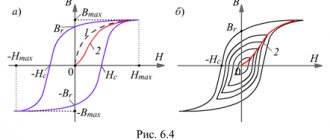
The magnetic field is described by two quantities: intensity H (proportional to the winding current) and magnetic induction B (characterizes the force action of the field in the material). The relationship between B and H is called the magnetization curve of a substance. In ferromagnets, it has an interesting feature - hysteresis (Greek: lagging) - when the instantaneous response to an influence depends on its background.
After leaving the zero point (this section is called the main magnetization curve), the fields begin to run along a certain closed curve (called a hysteresis loop). Characteristic points are marked on the curve - saturation induction Bs, residual induction Br and coercive force Hc.
Fig.1. Magnetic properties of ferrites. On the left is the shape of the hysteresis loop and its parameters. On the right is the main magnetization curve of 1500NM3 ferrite at various temperatures and frequencies: 1 - 20 kHz, 2 - 50 kHz, 3 - 100 kHz.
Based on the values of these quantities, ferromagnets are conventionally divided into hard and soft. The former have a wide, almost rectangular hysteresis loop and are good for permanent magnets. And materials with a narrow loop are used in transformers. The fact is that there are two types of losses in the transformer core - electrical and magnetic. Electrical (for excitation of Foucault eddy currents) are proportional to the conductivity of the material and frequency, but magnetic ones are smaller, the smaller the area of the hysteresis loop.
Ferrites are pressed powders of iron oxides or other ferromagnetic materials sintered with a ceramic binder. This mixture combines two opposing properties - the high magnetic permeability of iron and the poor conductivity of oxides. This minimizes both electrical and magnetic losses and allows transformers to be made that operate at high frequencies. The frequency properties of ferrites are characterized by the critical frequency fc, at which the loss tangent reaches 0.1. Thermal - Curie temperature Tc, at which μ abruptly decreases to 1.
Domestic ferrites are marked with numbers indicating the initial magnetic permeability and letters indicating the frequency range and type of material.
The most common is low-frequency nickel-zinc ferrite, designated by the letters NN. It has low conductivity and a relatively high frequency fc. But it has large magnetic losses and a low Curie temperature.
Nickel-manganese ferrite is designated NM. Its conductivity is greater, so fc is low. But magnetic losses are small, the Curie temperature is higher, and it is less afraid of mechanical shocks.
Sometimes ferrites are labeled with an additional number 1, 2 or 3. Usually, the higher it is, the more temperature stable the ferrite is.
What brands of ferrites are we most interested in?
Thermally stable ferrite 1500NM3 with fc=1.5 MHz, Bs=0.35..0.4 T and Tc=200 ℃ is good for converter technology.
For special applications, ferrite 2000NM3 is produced with standardized desacammodation (temporary stability of magnetic permeability). It has fc=0.5 MHz, Bs=0.35..0.4 T and Tc=200 ℃.
Ferrites of the NMC series have been developed for powerful and compact transformers. For example, 2500NMS1 with Bs=0.45 T and 2500NMS2 with Bs=0.47 T. Their critical frequency is fc=0.4 MHz, and their Curie temperature is Tc>200 ℃.
As for the permissible induction Bm, this parameter is adjustable and is not standardized in the literature. Approximately we can consider Bm = 0.75 Vsmin. For nickel-manganese ferrites this gives approximately 0.25 T. Taking into account the drop in Bs at elevated temperatures and due to aging, in critical cases it is better to play it safe and reduce Bm to 0.2 T.
The main parameters of common ferrites are summarized in Table 3:
| Brand | 100NN | 400NN | 600NN | 1000 NN | 2000 NN | 2000 Nm | 1000 NM3 | 1500 NM1 | 1500 Nm3 |
| μstart | 80..120 | 350.. 500 | 500.. 800 | 800.. 1200 | 1800.. 2400 | 1700.. 2500 | 800.. 1200 | 1200.. 1800 | 1200.. 1800 |
| fc, MHz | 7 | 3,5 | 1,5 | 0,4 | 0,1 | 0,5 | 1,8 | 0,7 | 1,5 |
| Tc, ℃ | 120 | 110 | 110 | 110 | 70 | 200 | 200 | 200 | 200 |
| Bs, T | 0,44 | 0,25 | 0,31 | 0,27 | 0,25 | 0,38.. 0,4 | 0,33 | 0,35.. 0,4 | 0,35.. 0,4 |
How hot will the core get?
Losses in magnets.
At a frequency less than critical fс, energy losses in the magnet consist mainly of losses due to magnetization reversal, and eddy current losses can be neglected.
Experience and theory show that energy losses per unit volume (or mass) during one magnetization reversal cycle are directly proportional to the area of the hysteresis loop. Therefore, the power of magnetic losses:
PH = P0 ⋅ V ⋅ f (8)
Where: P0 – specific losses per unit volume (measured at frequency f0 with induction B0); V – sample volume.
Table 4. Specific volumetric losses in ferrites 2500NMS at f0 = 16 kHz; B0=0.2 T:
| T, oC | P0, μW/(cm 3⋅Hz) | |
| 2500NMS1 | 2500NMS2 | |
| 25 | 10,5 | 8,5 |
| 100 | 8,7 | 6 |
However, with increasing frequency, the saturation induction decreases, the hysteresis loop is deformed, and losses increase. To take these factors into account, Steinmetz (CP Steinmetz, 1890-1892) proposed an empirical formula:
PH = P1 ⋅ m ⋅ ( f / f1 ) α ( B / B1) β (9)
It was agreed [7, Page 54] that f1 = 1 kHz, B1 = 1 T. The values of P1, α, β and core mass m are indicated in the reference book.
Table 5. Specific losses in some ferrites
| Brand | 1500NM3 | 2000NM1-A,B | 2000NM3 | 2000NM-17 | 3000 NM-A | 6000NM-1 | |||
| f | — | 0.4..100 kHz | 0.1..1 MHz | — | 0.4..100 kHz | 0.1..1 MHz | 0.4..200 kHz | 20..50 kHz | 50..100 kHz |
| P1, W/kg | 23,2 | 32±7 | 13±3 | 44,6 | 63±10 | 25±4 | 48±8 | 11±2 | 38±0,8 |
| α | 1,2 | 1,2 | 1,4 | 1,3 | 1,2 | 1,4 | 1,2 | 1,35 | 1,6 |
| β | 2,2 | 2,4 | 2,7 | 2,85 | 2,76 | 2,69 | 2,6 | ||
Copper losses.
Ohmic losses in the primary winding at room temperature and without taking into account the skin effect:
PM1 = I2 eff ( ρ / Sm ) ( ( D - d ) + 2h ) ⋅ n1 (10)
Where: Ieff - effective current, D - external, d - internal diameter of the ring, h - its height in meters; n1—number of turns; Sm - cross-section of the wire, in mm2; ρ = 0.018 Ohm ⋅ mm2 / m - resistivity of copper.
Total losses in all windings at elevated ambient temperatures:
PM = ( PM1 + PM2 + .. )⋅ ( 1 + 0.004⋅ ( T — 25oC ) ) (11)
Total losses in a transformer.
Magnetic and copper losses:
PΣ = PH + PM (12)
Estimated overheating temperature during natural convection:
ΔT = PΣ / ( αm Sool ) (13)
Where αm = (10..15) -4 W/(cm2oС), Sool = π /2 ( D2 - d2 ) + π h ( D + d )
Example 3:
Let's find the losses in the transformer from Examples 1 and 2. For simplicity, we assume that the secondary and primary windings are the same.
Effective current of the primary winding Ieff = 0.4 A.
Copper losses of the primary winding: PM1 = 0.42 ⋅ (0.018 / 0.08) ⋅ (28 - 16 + 18) ⋅ 10 -3 ⋅ 87 ≈ 0.1 W.
Copper losses of both windings: PM = 0.2 W.
According to reference data for ferrite 2000NM P1 = 32 W / kg; α = 1.2; β = 2.4; the mass of the K28x16x9 core is 20 grams.
Ferrite losses: PH = 32 ⋅ (30 / 1) ⋅ 1.2 ⋅ (0.25 / 1) ⋅ 2.4 ⋅ 20 ⋅ 10 -3 = 1.36 W
Total losses in the transformer: PΣ = 1.56 W.
Approximate efficiency = (40 - 1.56) / 40 ⋅ 100% ≈ 96%
How to take into account the inertial properties of a transformer?
In Fig.2. shows the T-equivalent circuit of the transformer. It includes the source resistance ri, the reduced load resistance R = n2 Rн or R = Pн / U2eff, where n = U1 / U2 is the transformation ratio, Ueff is the effective voltage of the primary winding.
Fig.2. Transformer equivalent circuit.
The inertial properties of the transformer are determined by the small leakage inductance Ls, the magnetizing inductance Lμ (almost equal to the inductance of the primary winding L1), the parallel winding capacitance Cp (the so-called dynamic capacitance) and the series capacitance between the windings Sp.
How to evaluate inductance and capacitance?
L1 is calculated using formula (5) or measured experimentally. According to [8], the leakage inductance in order of magnitude is equal to Ls ~ L1 / μ. The capacitance Cp is approximately 1 pF per turn.
The transformer works like a bandpass filter. At low frequencies it is a high-pass filter with a cutoff frequency ωн = R / Lμ. At high frequencies, elements Ls and Cp form a low-pass filter with a cutoff frequency ωв ≈ (Ls Cp)-1/2. The series capacitance Cn is small and has practically no effect on operation.
The model has two characteristic resonances:
Low-frequency (magnetization resonance) in a parallel circuit Lμ Average. Its frequency is fμ ≈ ( 1/ 2 π ) ⋅ ( Lμ Cp )-1/2 , and its quality factor Qμ ≈ ( ri || R ) ⋅ ( Lμ / Cp )-1/ 2 (14)
High-frequency (scattering resonance) in the circuit formed by Ls and Cр. Its frequency fs ≈ ( 1/ 2 π ) ⋅ (Ls Cp )-1/2, and its quality factor Qs ≈ ( Ls / Cp)1/2 / ri (15)
How do winding resonances affect?
The amplitude-frequency response of the transformer is similar to the frequency response of a bandpass filter, but at its upper edge the resonance fs gives a characteristic peak.
The response to voltage pulses depends on the method of switching on the source and the resistance values of the circuit.
With a low internal resistance of the source ri, only resonance fs appears in the form of a characteristic “ringing” at the pulse fronts. If the source is connected through a switch, then when it is opened, intense oscillations with a frequency fμ may occur.
Fig.3. An example of frequency response and transient process in a transformer. Its equivalent circuit is given below in Figure 4.
Experimental measurement of pulse transformer parameters.
For the sample, a ring of 3000NM ferrite of size K10x6x2 was taken. The primary winding was 21 turns; secondary 14; transformation ratio n = 1.5; load resistance was 4.7 kOhm; The source was a rectangular pulse generator on TTL microcircuits with a level of 6V, a frequency of 1 MHz and an internal resistance of ri ≈ 200 Ohms.
Let's calculate the theoretical parameters:
Sc = 4 ⋅ 10 -6 m2, la = 25.13 ⋅ 10 -3 m, ALtheor = 600 nH/vit2, L1theor = 0.6 ⋅ 212 = 265 µH, Ls theor ≈ 265/3000 = 0.09 µH, Cp theor ≈ 21+14 = 35 pF. Reduced load resistance R = n2 Rн = 2.25 ⋅ 4.7 ~ 10 kOhm.
Results of inductance measurements using the AKIP-6107 device:
L1 = 269 µH, L2 = 118 µH, short-circuiting the secondary winding we get 2Ls = 6.8 µH, which is two orders of magnitude higher than its theoretical estimate.
The dynamic capacitance Cp can be estimated using formula (15) by applying rectangular pulses to the transformer and using an oscilloscope to measure the period of “ringing” oscillations at the pulse fronts at the output of the secondary winding. The “ringing” frequency fs turned out to be 18.5 MHz, which gives Cp ≈ 21 pF and is in good agreement with the theoretical estimate.
For comparison with experiment, an equivalent circuit with measured parameters was simulated in the LT Spice program.
Fig.4. Transformer model. Vout is the reduced voltage, the actual one will be n times less.
Fig.5. Experiment results. The vertical scale is 1 volt per division.
So, the model built on the basis of measured Lμ, Ls and Cp is in complete agreement with experiment.
The theoretical estimate [8] of a capacitance of 1 pF per turn for small rings is acceptable, but the estimate of the leakage inductance differs by two orders of magnitude from the actual one. It is easier to determine it experimentally.
Appendix 1. Derivation of the formula for the number of turns.
When voltage U is applied to the winding, an induced emf E will appear in it: U = -E = n Sc dB / dt
For a sinusoidal voltage with amplitude Um: Um = n Sc ω Bm Where does the number of turns come from: n = Um / ( Sc ω Bm )
Expressing the circular frequency in terms of the usual frequency, and the area in cm2, we obtain the engineering formula:
n = 0.16 ⋅ 104 / ( f ⋅ Bm⋅ Sc )
For a rectangular voltage of magnitude Um, the induction increment is: dB = dt Um / ( n Sc) Integrating it over time from 0 to T/2 and taking into account that in half a period the field will change from -Bm to +Bm we obtain: 2Bm = ( T / 2 ) Um / ( n Sc )
Expressing the period in terms of frequency and the area in cm2, we obtain the engineering formula:
n = 0.25 ⋅104 / ( f ⋅ Bm ⋅ Sc )
It is suitable for both cases.
Appendix 2. Derivation of the formula for the overall power of the transformer.
According to Faraday's law of electromagnetic induction, the relationship between the voltage on the coil and the change in magnetic induction in it:
U dt = n Sc dB
During the time from 0 to T/2, the induction will change from -Bm to +Bm. Integrating within these limits we obtain the average voltage:
Uav = 4n ⋅ Sc ⋅ Bm ⋅ f
Where:
But the devices do not measure the average, but the effective voltage, which is equivalent to constant energy. The relationship between the average and effective voltage gives the form factor kf = Ueff / Uav. For a meander it is equal to 1, for a sine it is 1.11.
Hence the effective voltage on the coil: Ueff = 4 ⋅ kf ⋅ n ⋅ Sc ⋅ Bm ⋅ f
We will estimate the overall power from the following considerations. The frequency f is not high, the losses due to eddy currents and magnetization reversal are small, and the power is limited only by overheating of the winding. It is determined by the maximum current density j, which is the same for both windings.
Let us define the overall power as half the sum of the powers of the primary and secondary windings.
Pgab = ( P1+P2 ) / 2 = ( Ueff1⋅ I1 + Ueff2 ⋅ I2 ) / 2 = j ( S1 n1 + S2 n2 ) 4 kf Sc Bm f / 2
Where S1 and S2 are the turning areas of the primary and secondary windings.
This relationship can be written in terms of copper area Sm:
Pgab = 2⋅ kf ⋅ f ⋅ Sc ⋅ Sm ⋅ Bm ⋅ j
The copper area is associated with the window fill factor σ = Sm / So.
Sigma is a certain empirical coefficient, equal to a minimum of 0.15 for a single-layer winding and a maximum of 0.4 for a multilayer winding (it won’t fit anymore).
As a result, our formula looks like:
Pgab = 2 ⋅ kf ⋅ σ⋅ f ⋅ Sc⋅ So ⋅ Bm ⋅ j
All quantities here are in SI.
Let us assume that the voltage has the shape of a meander, kf = 1. Choosing the current density j = 2.2 A / mm2; fill factor σ = 0.15; expressing the area in cm2; Bm to T; frequency in Hz we obtain the calculation formula:
Pgab = Sc ⋅ So ⋅ f ⋅ Bm / 150
As you can see, this formula was derived with a large margin; in fact, you can get more power from a transformer.
Literature.
- Kosenko S. “Calculation of a pulse transformer of a push-pull converter” // Radio, No. 4, 2005, p. 35 - 37, 44.
- Eranosyan S. A. Network power supplies with high-frequency converters. — L.: Energoatomizdat. Leningr. department, 1991, - 176 p.: ill.
- S. V. Kotenev, A. N. Evseev. Calculation and optimization of toroidal transformers and chokes. - M.: Hotline-Telecom, 2013. - 359 p.: ill.
- A. Petrov “Inductances, chokes, transformers” // Radio Amateur, No. 12, 1995, pp. 10-11.
- Mikhailova M.M., Filippov V.V., Muslakov V.P. Soft magnetic ferrites for electronic equipment. Directory. - M.: Radio and Communications, 1983. - 200 p., ill.
- Calculated geometric parameters of ring cores.
- B.Yu. Semenov. Power electronics for amateurs and professionals. M.: Solon-R, 2001. - 327 p. : silt
- Course of lectures “Pulse technology” for 4th year students of the Department of Radiophysics. Chapter 3.
Physical concept of winding inductance
Inductance is the coefficient of proportionality between the current produced by a closed electrical circuit and the magnetic flux produced by that circuit.
A more understandable formulation would be the one that talks about the magnitude of the self-inductive emf in a closed loop, which occurs when the current strength changes per unit time. That is, the concept of inductance is valid for a changing current.
With direct current, talking about inductance is meaningless.
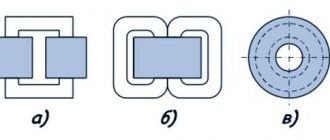
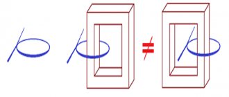
In an ideal transformer, the entire electromagnetic field created by the windings is confined to the magnetic core. In real designs, there is a stray field, the magnitude of which depends on the method of making the coil and the design features of the core. The greater the thickness of the winding, the larger part of the electromagnetic field is closed outside the magnetic circuit.
This is also facilitated by the build quality of the magnetic circuit. The gaps between the plates contribute to a sharp increase in dissipation. In this regard, O-shaped cores have the best properties.
What does the EMF in the windings of a transformer depend on?
In the previous article, I indicated that the instantaneous value of the EMF in the transformer winding is determined by the number of turns ω of the wire in it and the rate of change of the magnetic flux dΦ/dt
where ω is the number of turns of the transformer winding,
dFV/dt – rate of change of magnetic flux.
However, in most cases, we are not interested in the instantaneous value of the emf, but in the effective one. Therefore, we derive an expression that determines the effective value of the EMF in the windings of the transformer. This can be done analytically by integrating the function of change in magnetic flux dΦ/dt, or by finding the average value of the emf Ecp and the shape factor of the emf kf. I will output the expression using the second method.
The magnetic flux flowing in the transformer core changes in accordance with a certain periodic function and has two amplitude values: maximum +Фm and minimum –Фm, then the total change in magnetic flux over half-cycle T/2 will be
Then the average value of the EMF Еср in the transformer winding will have the form
where ω is the number of turns of the transformer winding,
T/2 – half-period of change in the magnetic flux function,
f – frequency of magnetic flux change,
Фm is the amplitude of the magnetic flux.
The effective value of the EMF and its average value are related by the shape coefficient of the EMF curve kf, then the effective value of the EMF in the transformer winding will be determined by the following expression
where kf is the EMF shape coefficient,
f – frequency of EMF change,
ω – number of turns of the transformer winding,
B – magnetic induction in the core,
Sc is the cross-sectional area of the transformer core.
Let us give examples of the effective value of the EMF for sinusoidal, rectangular (meander) and triangular changes
From the above it follows that, provided that the electromagnetic induction B is constant, the EMF is proportional to the design parameters of the transformer, the cross-section of the magnetic circuit Sc and the number of turns ω. The correct choice of the value of electromagnetic induction B is one of the key tasks when designing a transformer. In addition, with increasing frequency f, the EMF increases, therefore, to realize the same EMF with increasing frequency, smaller dimensions and weight of the transformer are required. This factor is the main advantage of high-frequency transformers, which are most often used nowadays.
Formulas and measurement
The formulas for calculating the inductance of coils are quite complex and have different forms for different types of windings:
- linear conductor;
- single turn coil;
- flat coil;
- solenoid winding;
- toroidal shape.
The greatest difficulties arise when calculating multi-turn multilayer coils, that is, those that make up the windings of transformers.
In the vast majority of cases, an accurate calculation is impossible, so you have to use approximate data and clarify them after measurements.
Formulas for calculating transformer inductance are based on solenoid calculations:
L=µ0µN2S/l, where
µ0 – magnetic constant;
µ – magnetic permeability of the core;
N – number of turns;
S – area of one turn;
l – winding length.
To measure inductance, there are several methods and instruments created on their basis. In most cases, the measurement is made by calculating the inductive reactance of the coil when applying a reference voltage of a given frequency and the measured value of the current through the winding.
In specialized instruments, calculations are performed automatically, and the user only reads the instrument scale, expressed in inductance units - H, mH or μH.
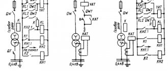
Symbol of transformers in the diagrams:
Figure 1 - UGO transformers.
- – transformer with ferrite core;
- – a transformer with a magnetodielectric core, i.e. dielectric magnetic material;
- – transformer with a ferrite core with 2 secondary windings;
- – a transformer with a ferrite core with taps from the secondary winding.
Next to the symbol, the type of element (T) and the serial number are indicated; the transformation ratio can also be indicated next to the symbol (not a mandatory requirement).
How to measure at home
Instruments for directly measuring inductance are expensive and are rarely used at home. Results can be obtained with acceptable accuracy using conventional instruments for measuring alternating current: an ammeter and a voltmeter. An ohmmeter is also needed.
The procedure is as follows:
- Using an ohmmeter, determine the active resistance of the winding R.
- Connect the transformer in series with the ammeter to the network.
- A voltmeter is connected parallel to the winding.
- According to the instrument readings, the impedance of the transformer is determined: Z=U/I
- Inductive reactance is found by subtracting active resistance from impedance: XL=ZR
- Inductance is determined by the formula: L=XL/(2πf), where π is pi 3.14, f is the measurement frequency.
As a rule, the active resistance of the winding is significantly (several orders of magnitude) less than the inductive one, so it can be ignored. This is why connecting a transformer to a DC voltage circuit causes a short circuit. The winding current will be limited only by the active resistance.
Transformer markings:
Since the dimensions of even high-frequency transformers are not so small compared to other electronic devices, the information is usually indicated explicitly.
The following is indicated on the transformers:
- Type of transformer, for example, TP - power transformer (i.e. power);
- Operating voltage of the primary and all secondary windings;
- Either the rated power or the maximum current for each secondary winding is indicated;
- Number of secondary windings;
- Operating frequency;
- For instrument transformers, the class accuracy is indicated;
- For matching transformers, the inductance of the windings is indicated.
Physical features of the process
The optimal flow rate is determined by the characteristics of the device. Passing the path from the generator (place of generation) to the consumer, electrical energy is transformed. In the generator, the indicators are higher, since the current will travel long distances (from 1-10 meters to 1-10 km). Standard indicators are 10 kV. According to the established rules, the consumer must receive electricity with a power of 380 or 220 V. A transformer with a rotating magnetic field allows you to achieve the necessary changes.
Starting mode of operation of a transformer for a resonant load
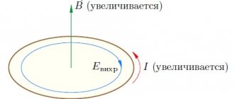
The starting mode must ensure a normal transient process and the output of the operating point of the hysteresis loop to a symmetrical private cycle in operating mode. If initially the magnetic circuit of the power transformer was completely demagnetized, when a voltage with the frequency of the resonant circuit is applied to the transformer, the center of the partial cycle of the magnetization loop shifts along the main magnetization curve from point O to point O1, so the working induction is doubled in relation to its steady-state value ( Fig. 11a).
Simulation of the transient process during startup showed that the transformer is demagnetized (Fig. 11b) with a time constant τ determined by expression (4). In this case, it is clear that the amount of overregulation of the transformer induction reaches double the value. To eliminate overshoot, it is recommended to start the inverter at an increased frequency, correspondingly twice the resonant one. As the power transformer is demagnetized, the frequency can be iteratively approached to the resonant one, while the size of the adjustment step should not lead to an excess of the operating induction (Fig. 11c).
Rice. 11. Transient process when starting a transformer: a) the first cycle of the magnetization loop; b) the process of transformer demagnetization; c) normal start-up of the transformer
Transformer magnetization process
A typical structure of a frequency converter for an induction heating installation, built on the basis of a series resonant voltage inverter loaded through a matching transformer TV1 onto a series resonant circuit formed by an inductor with a heated part having an active-inductive resistance (Rн, Li), and a compensating capacitor C, is shown in Fig. 1. During the heating process, the load parameters change significantly, which leads to a change in the resonant frequency of the oscillatory circuit; therefore, a phase-locked loop unit is introduced into the control system of the frequency converter, which continuously tunes the inverter to the resonant frequency. In this case, a single occurrence of asymmetry is possible when the duration of one of the half-cycles of the supply voltage changes, which is determined by the ratio of the duration of the adjustment step to the resonant period.
Rice. 1. Typical circuit of the UIN frequency converter
If a symmetrical rectangular voltage is applied to the matching power transformer TV1, its magnetic circuit is remagnetized along a symmetrical partial hysteresis loop (Fig. 2) and the magnetic induction in it changes from the value +Br to the value –Br. However, the spread of dynamic parameters of IGBT transistors, matching drivers and phase-locked loop systems leads to unequal duration of half-cycles of the output voltage and, as a consequence, to the appearance of a constant component of the voltage applied to the transformer Uav and biasing of the power transformer with direct current [1], the magnitude of which can be determine by the ratio
Where
is the average voltage value on the primary winding during the resonant period T, Rob1 is the resistance of the primary winding. This leads to a displacement of the center of the partial hysteresis loop along the main magnetization curve from point O to point O1 (Fig. 2), corresponding to the field strength H0 from the magnetizing force of direct current. H0 is determined according to the law of total current
where W is the number of turns of the primary winding; lc is the length of the transformer magnetic power line.
Rice. 2. Displacement of the partial hysteresis loop of the magnetic circuit of a power transformer in the presence of DC bias
Thus, the current ILμ of the magnetizing inductance of the transformer Lμ can be conditionally divided into an alternating component, which ensures magnetization reversal of the magnetic circuit, and a direct component, called the bias current I0 and determined by the value of the constant component of the asymmetry voltage Uav.
Magnetization of a power transformer leads to magnetization reversal of its core in an asymmetrical cycle (curve 2), which, with a sufficient value of the bias current, leads to saturation of the power transformer and an unlimited increase in the primary winding current, despite the small value of Bp (Fig. 3). As a result, overload and failure of the inverter power transistors occurs.
Rice. 3. Biasing of the magnetic circuit with direct current: a) primary winding current; b) transformer magnetizing current
Currently known methods for solving the problems of power transformer bias can be conditionally reduced to four groups:
- Introduction of feedback on the leakage flux or magnetizing current of the power transformer. In this case, with an increase in the bias current, correction of the duration of control pulses must be carried out in each control cycle [4].
- Selection of the magnetic core of a transformer with a non-rectangular magnetization loop shape [3]. It should be noted that the longer the length of the magnetic field line and the lower the magnetic permeability of the ferromagnetic material of the magnetic core, the more resistant the power transformer becomes to DC bias (Fig. 2), since the constant component of induction (Bo) caused by the bias current (Io ), turns out to be significantly less than the range of changes in working induction (Bp).
- Introduction of a non-magnetic gap into the magnetic core of a transformer, which has a powerful demagnetizing effect, leading to a shift in the hysteresis loop and a noticeable decrease in the magnetic permeability of highly permeable materials while reducing the residual induction Br. In this regard, the useful range of induction increases significantly [3]. Small gap sizes do not actually affect losses in the magnetic core, but they have the necessary demagnetizing effect, which prevents rapid saturation of the magnetic circuit when exposed to a direct current field.
- Inclusion of a separating capacitor in the primary winding of the transformer (Fig. 5), which leads to symmetry of the position of the working hysteresis loop. In this case, the bias current of the power transformer is completely absent due to the fact that the average value of the separating capacitor current in steady state is zero.
When comparing these methods, the following features of their implementation should be noted. The first method is universal, but in practice it is associated with significant difficulties in measuring the controlled parameters (leakage flux and bias current). In addition, with significant asymmetry, the current growth through the primary winding of the transformer in each period occurs at a high speed, which can lead to a situation where the pulse duration limitation does not have time to correct the asymmetry [4].
The second method is the simplest, but its use does not exclude the bias current, as a result of which it is necessary to increase the working induction margin in relation to the saturation induction, which must include a constant Bo level due to the bias current.
The introduction of a non-magnetic gap is an effective method of combating magnetic core bias and makes it possible to reduce the displacement of a particular cycle of the magnetization loop when exposed to significant asymmetries. However, in this case, as in the previous one, it is not possible to completely eliminate the bias current.
In resonant circuits, the most effective is the fourth method, which completely eliminates the transformer bias current, making it possible to balance a particular cycle of the hysteresis loop under the influence of significant asymmetries and a relatively small operating induction margin.