The operation of various modern means of communication is impossible without such devices for receiving and transmitting radio waves as short-wave antennas (abbreviated as HF antennas). The demand and popularity of these devices is due to the wide variety of their types, as well as the possibility of self-production. They are especially common in amateur radio communications with the permitted broadcast range from 1.81 to 29.7 MHz.
Classic HF antenna
Helix antennas
DIY Mimo 4g lte antenna
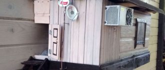
The classic device of this type (“Tesla Spiral”) consists of two spirals located on crosspieces connected to each other by a jumper (traverse).
Tesla Spiral
Antenna power
Such a device is connected to a transceiver (receiving and transmitting equipment) with a thick coaxial cable with a characteristic impedance of 50-75 Ohms.
Antenna assembly
A small device of this type is assembled by winding two flat spirals with a diameter of 90 cm onto a frame made of polypropylene pipe, consisting of two crosses and a 90-92 cm crossbar connecting them. Single-core insulated copper wire with a diameter of 1.5 mm is used as the material for the spirals.
Transformer
For this device, an air transformer is used with an operating wave range from 10 to 100-160 meters. It is made by winding 16 turns of double wire 1.5 mm thick onto a hollow 140 mm frame with a diameter of 25 mm. The length of the wire winding should be 95-100 mm.
Antenna setup
The setup process includes the following operations:
- Setting the SWR (standing wave ratio) is done using a special device or alligator clips fixed on the vibrator spirals and moved along them, which leads to a change in the position of the power point. The VSC value obtained during tuning at the found frequency should be within 1.0-1.2.
- Adjusting the resonance frequency is done by changing the length of the vibrator wires using the same clamps as in the previous paragraph. The adjustment is made by moving the clamps along the insulated wire of the spirals.
Antenna gain, bandwidth and beam angle
The helical transmitting antenna is placed horizontally at a height equal to 1/8 of the wavelength it emits.
The simplest HF antenna. Half-wave Dipole.
I myself was in their “shoes” and thought and acted in approximately the same way, but still returned to the “Half-wave dipole” antenna, which is the easiest to manufacture and configure. In this article I will describe the simplest and most inexpensive way to build a half-wave dipole antenna and configure it. And so, rather than get bogged down in formulas, let’s use online calculation. Below are the dimensions for the 40m range.
And so we take a copper antenna rope or an electrical wire (for example, with a cross-section of 2 squares) and cut the arms into 10 m sections. I will not go into debate here about which material is better for making an antenna. Probably the best material is the one you have on hand or got for free (just kidding). It should be noted that the electrical length of the antenna is slightly different from the physical length calculated.
Below is an example of how you can easily make a dipole
After the elements are cut, a central insulator and an insulator for the ends of the blades are made. You can hang a dipole in space. The recommended suspension height is not lower than 1/4 long wavelength for the selected range. It’s better, of course, as high as possible, but if the height of the suspension is below 1/4, it’s also not a big deal, the antenna will just not work as efficiently. Because a reactive component will be introduced. But more on that later.
The dipole is manufactured, suspended, connected to the transceiver. Can everyone work? I guess, yes. But we do not know the value of the SWR and whether the antenna resonance lies in the required frequency range. Therefore, working with such an antenna will be ineffective. So we need to set up the antenna. To do this, you can use an SWR meter or an antenna analyzer. The SWR meter shows us the degree of coordination between the antenna and the transceiver. The value of a well-tuned antenna should tend to 1, but it is quite acceptable to conduct communications on antennas with SWR up to 3. The antenna analyzer shows us slightly larger parameters - these are SWR, active and reactance of the antenna. All these indicators are of great importance, but at the initial stage they are not so important.
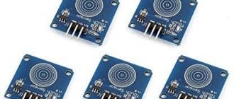
This is what the SWR meter looks like (well, at least one of a million options)
Well, the Antenna Analyzer
Unfortunately, not every radio amateur can afford to buy an antenna analyzer, but an SWR meter is quite affordable.
Let's start setting up the antenna. Let's connect the SWR meter between the transceiver and the antenna. And we will measure the SWR value at the beginning, middle and end of the required range. Ideally, the value should be 1 in the entire area, but this is ideal. But in reality, the dipole has a wave impedance of 75 ohms, so we get a value of at least 1.5. But this should not be scary because... Let me remind you that you can work with SWR up to 3. Further, a good SWR level will most likely lie lower in frequency, because remember I said that the physical and electrical lengths of the antenna differ. Therefore, it is necessary to either shorten or lengthen the antenna. The main thing to remember is a few rules when setting up an antenna:
- Shortening should be done not by cutting off an excess piece, but by bending it towards the main arm (true for wire antennas)
- If the gap often with a good SWR lies lower in frequency, then the antenna must be shortened; if higher, then lengthen
- And the most important thing. Best the enemy of the good. Although there is no limit to perfection.
And so, after several measurements, we come to the conclusion that the physical length of the antenna is somewhat longer, because The frequency band with good SWR lies in the range of 6900-7000 MHz. You can, of course, immediately shorten the antenna strips, but to do this you need to know the shortening factor of the wire (the material from which the antenna strips are made). Therefore, it is necessary to shorten the arms of the dipole several times (at least 2) by the same small distance in order to determine by how many kHz the frequency is shifted. And only then, taking into account this dependence, shorten the arms of the dipole to the required length.
That's all. The easiest way to make and configure an antenna is a half-wave dipole. Of course, I did not take into account the reactive component when setting up the antenna, but I considered the simplest method. You can start working on air.
Good luck to everyone and traditional 73.
Magnetic antennas
DIY digital TV antenna
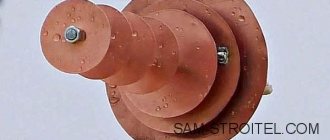
The most common HF antenna design is a magnetic loop , consisting of:
- Duralumin or copper radiating ring with a diameter of 25-80 cm;
- Communication loops, the diameter of which is 5 times smaller than that of the radiating ring;
- Supply cable (feeder) with a characteristic impedance of 50 Ohms;
- A powerful capacitor adjusts the resonant frequency.
Magnetic frame loop
Such simple homemade transmitting devices are installed both on high masts, roofs of high-rise buildings, and on balconies or window sills of apartments. Thanks to a tuning capacitor capable of operating at a power of up to 100 W, such amateur radio shortwave antennas operate in the range from 1.8 to 27 MHz.
HF Antennas
Radio amateurs have been using the Windom antenna for almost 90 years, which got its name from the name of the American shortwave operator who proposed it. Coaxial cables were very rare in those years, and he figured out how to power an emitter half the operating wavelength with a single-wire feeder.
It turned out that this can be done if the antenna feed point (connection of a single-wire feeder) is taken approximately at a distance of one third from the end of the emitter. The input impedance at this point will be close to the characteristic impedance of such a feeder, which in this case will operate in a mode close to the traveling wave mode.
The idea turned out to be fruitful. At that time, the six amateur bands in use had multiple frequencies (non-multiples of WARC bands did not appear until the 70s), and this point turned out to be suitable for them as well. Not an ideal point, but quite acceptable for amateur practice. Over time, many variants of this antenna appeared, designed for different bands, with the general name OCF (off-center fed - with power not in the center).
In our country, it was first described in detail in the article by I. Zherebtsov “Transmitting antennas powered by a traveling wave,” published in the journal “Radiofront” (1934, No. 9-10). After the war, when coaxial cables came into amateur radio practice, a convenient power supply option for such a multi-band emitter appeared. The fact is that the input impedance of such an antenna in the operating ranges does not differ very much from 300 Ohms. This allows you to use common coaxial feeders with a characteristic impedance of 50 and 75 Ohms through HF transformers with a transformation ratio of 4:1 and 6:1 to power it. In other words, this antenna easily became part of everyday amateur radio practice in the post-war years. Moreover, it is still mass-produced for shortwave frequencies (in various versions) in many countries around the world.
It is convenient to hang the antenna between houses or two masts, which is not always acceptable due to the real circumstances of housing, both in the city and outside the city. And, naturally, over time, an option arose to install such an antenna using just one mast, which is more feasible to use on a residential building. This option is called Inverted V - Windom.
The Japanese shortwave operator JA7KPT, apparently, was one of the first to use this option for installing an antenna with a radiator length of 41 m. This length of the radiator was supposed to provide it with operation in the 3.5 MHz range and higher frequency HF bands. He used a mast 11 meters high, which for most radio amateurs is the maximum size for installing a homemade mast on a residential building.
Radio amateur LZ2NW (https://lz2zk. bfra.bg/antennas/page1 20/index. html) repeated his version Inverted V - Windom. Its antenna is shown schematically in Fig. 1. The height of his mast was approximately the same (10.4 m), and the ends of the emitter were spaced from the ground at a distance of about 1.5 m. To power the antenna, a coaxial feeder with a characteristic impedance of 50 Ohms and a transformer (BALUN) with a coefficient of transformation 4:1.
Capacitive antennas
Multiband antenna
A multi-band antenna is a device that allows broadcasting in all short wave bands permitted for amateurs. Thanks to this property, multi-bands have become very popular and widespread.
One of the UA1DZ type multi-bands has the following design:
- Vibrator 9.3 m long
- 3-meter stand;
- 4-5 quickdraws;
- 10-14 additional flexible counterweights, 9.4 m long.
The connection of such antennas and transmitters is made using a 50 Ohm coaxial cable.
The main disadvantages of such multi-band structures are their bulkiness, high windage and the risk of lightning when installed on the roof of a high-rise building or other multi-story building.
Vertical Antenna (Ground Plane)
Vertical Ground Plane antennas are devices designed for broadcasting in the ranges from 14 to 24-28 MHz. The main components of such vertical HF antennas are a 2-meter mast, a duralumin vibrator 2 to 5 meters long, 4-5 counterweights 2.5-3 meters long and a 50-ohm coaxial supply cable.
They are installed both on the roofs of high-rise buildings and on the gables of private houses.
Short dipole antenna
The simplest device of this type at 7 MHz is a structure consisting of the following parts:
- A wire vibrator divided into two 3-meter arms with insulators and guys at the ends. Small pieces of textolite are used as insulators; durable nylon linen cord is used for guy ropes.
- Two extension 140-turn coils made of copper wire 0.5-0.6 mm thick;
- Central unit with transformer (balun);
- Feeder – 50 Ohm supply coaxial cable.
Short dipole
Such a shortened dipole is used both in stationary and field conditions, fixing it at a height of 3 to 4 meters.
On a note. In order to tune such a device for resonance, it is necessary to uniformly shorten the length of the horizontal or angled arms of the vibrator. After changing the length of the arm, the guy that shortens it is attached to the nearest tree or other stable support.
All-wave antenna of the “poor” radio amateur
When designing and operating your “antenna field,” you have to constantly maneuver on a tiny patch of roof between elevator boxes, ventilation shafts, all kinds of television, satellite and other antennas, various cable communications, open radio broadcasting wiring... In addition, one should take into account the very detrimental all-season “ harvest season"