A capacitive sensor, as defined by the Great Soviet Encyclopedia, is a measuring transducer that allows non-electrical quantities to be converted into electrical capacitance values. For example, such as pressure, liquid level, mechanical force, humidity, and others. Changes in capacitance turn out to be proportional to fluctuations in the measured quantity, and this correspondence makes it possible to track its behavior.
How does this meter work?
In essence, such a sensor is a capacitor. The operation of the meter and control of parameters are based on determining its characteristics. Therefore, it is quite appropriate to remember what a capacitor is.
About the capacitor, its characteristics
As is known, the capacitance of a capacitor is determined by the formula
С=Ɛ×Ɛ0×S/d
Where:
- Ɛ0—dielectric constant;
- Ɛ is the relative dielectric constant of the medium between the plates;
- d - gap between plates;
- S is the area of the plates.
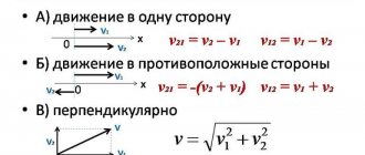
There are three variables in this formula - the dielectric constant Ɛ, the area S of the capacitor plates and the gap between the plates d. Changing any of them will lead to a change in capacitance, and tracking fluctuations will allow you to monitor the characteristics of the environment or other parameter.
Operating principle of a capacitance meter
The simplest technical solution is to include a measuring sensor in the timing circuit of the generator. Without going into the intricacies of circuit design, we can say that the principle of operation of any capacitive sensor is in one way or another connected with changing the parameters of the generator. This occurs due to fluctuations in the capacitance of the capacitor, which leads to the generation of oscillations of a different frequency.
Thus, by monitoring its value at the output of the meter, it is possible to evaluate changes in the controlled parameter. Of course, in each specific case the circuit design may be different. It will largely depend on the parameter of the capacitor, which is influenced by the external environment.
This may be a change in the gap between the capacitor plates due to their approach or removal. Or when filling the tank with another medium, for example water, the value of the dielectric constant will change. Or the capacitor plates will be positioned differently relative to each other after external influences.
Any such impact will cause a change in the capacitance value of the capacitor, and therefore affect the operation of the circuit. For example, capacitive level sensors monitor the filling level of a tank or hopper. Knowing the relationship between the liquid level and the capacitance of the condenser, you can determine how full the tank is.
Although it should be noted that other methods of processing sensor signals can be used. There are quite a lot of them, the choice of one or another depends on specific conditions. The current level of electronics development makes it possible to obtain a processed signal in the form of a digital code.
Another method for measuring capacitance is using analog-to-digital converters. Microcontrollers can handle this task quite well. In this case, the measuring part of devices based on them is significantly simplified.
Shielding and capacitance measurements
One of the problems with capacitive proximity meters is that field lines will propagate to any adjacent cells at ground potential. Many parasitic phenomena (for example, ground traces (a path on the Earth's surface left by an airplane or satellite)) affect the sensitivity and detection distance of the sensor. This phenomenon poses a problem for noise-sensitive systems.
Parasitic effects on printed circuit boards (a) that affect the quality of device operation are reduced using protective electrodes. Shield drivers are included in the interface devices of capacitive sensors and specialized microcontrollers.
Adding an active screen can help eliminate environmental impacts and allow you to use your device to its full potential. A well-designed active shield will face the output of the sensor and direct its signal in the desired direction.
The protection driver is an active output that operates at the same voltage as the device itself. Thus, there will be no potential difference between the screen and the input of the device. Any external interference will cause minimal interaction between the shielded electrode and the measuring electrode.
What types of sensors are there?
All meters based on a capacitive sensor can be divided into:
- single-capacity;
- two-capacity.
It should be noted that the design of capacitive sensors can be:
- flat;
- cylindrical;
- rotary.
The scope of application of any of them is quite extensive. As an example, according to their functional purpose they can be used in the role:
- level meters;
- angular movement monitoring devices;
- motion sensors;
- inclinometers;
- pressure sensors.
These examples do not exhaust the options for using capacitance meters. Other opportunities provided by these devices will be discussed below.
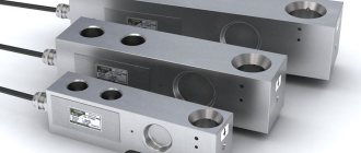
Single capacitive sensors
These are the simplest sensors. In fact, they are ordinary capacitors of variable capacitance, changes in which are monitored by a special circuit. Capacitance meters of this type are subject to strong influence from the external environment. It is best to use them to implement various non-contact control options, for example, the approach of unauthorized persons to the protected area or movement in it.
What such capacitors look like in practice can be understood from the figures below.
Dual capacitance sensors
Allows you to reduce the influence of the external environment. A capacitive sensor of this type is characterized by greater measurement accuracy due to the fact that one capacitor serves as a reference. This allows you to compensate for outside influence. Two-capacitance sensors are differential and semi-differential. Schematic examples of constructing such devices are shown below.
Another way to increase the sensitivity of a capacitance meter is to use a bridge circuit.
Level sensors
Capacitive level sensors are devices that allow you to monitor the level of liquid or granular substances in a tank or hopper. Of course, the design of the meter options for different substances will be different, but the principle will remain unchanged.
In fact, capacitive level sensors of this type are two capacitors connected in parallel. Only in one the dielectric is air, and in the other it is a liquid or other substance. Thus, the capacity of each of them will be different, it will change and depend on the degree of filling of the bunker (tank).
The given drawing or diagram of a capacitive sensor is distinguished by its simplicity of construction and versatility. However, in order to increase the accuracy of the measurement, it is best to at least additionally control the temperature of the liquid; the value of the dielectric constant depends on it. And depending on the temperature, it will be necessary to use a correction factor in the calculations.
Linear motion sensors
Such devices can be used for a variety of purposes, for example:
- control of the beginning and end of the working stroke of the actuator in automatic machines;
- positioning of various objects;
- recording the appearance of a third-party object in the alarm system;
- like a limit switch.
Sensors of this type can operate on different principles. Below we will consider two options for their implementation.
- Based on changes in the gap between the capacitor plates.
In this embodiment, the impact falls on one of the plates; it can shift under the applied force, which causes a change in the capacitance of the capacitor, proportional to the impact. - In the embodiment presented below, the operation of the sensor is based on a change in the dielectric constant of the dielectric between the plates.
Angle sensors
At their core, such sensors are similar to linear displacement sensors, and most often devices with variable area are used for these purposes. One of the capacitor plates is attached to the object's shaft, while the other remains stationary. Changing the degree of plate overlap causes capacitance fluctuations.
To increase measurement accuracy, multi-section transducers are most often used.
Inclinometer
The operating principle of such a device is similar to how a capacitive level sensor works. A substrate is attached to a special capsule, on which two isolated sections are located, which are one of the terminals of the capacitor. Inside the capsule is filled with a conductive liquid. It is the other electrode of the capacitor. Its capacity is determined by the vertical position of the device and does not depend on the angle of inclination in other directions.
Pressure meter
In such a meter, pressure causes a change in the distance between the capacitor plates. This is achieved by the fact that between its plates there is an elastic membrane, which is affected. The partition, depending on the pressure, moves in one direction or another, which leads to a change in capacity.
Automation using level sensors
Photo relays and principles of their operation
We have ready-made solutions for automation and dispatch of water utilities, as well as for monitoring and control of sewage pumping stations, enterprise collectors and control of the discharge of non-cooled water from thermal power plants. The systems are autonomous and have an archive.
We offer centralized monitoring and control systems for wells and the operation of pumping mechanisms. The use of our instruments and systems allows the user to obtain reliable data on well production, flow rate, level, pressure and other parameters.
We supply secure instrumentation. Including explosion-proof liquid level sensors and intrinsically safe transmitters and relays for a wide range of industries. For example, our devices are capable of operating at air temperatures below – 35*C or at a hazardous oil refining production site.
Our customers include almost all regions of Russia, for example, the cities: St. Petersburg, Moscow, Novy Urengoy, Murmansk, Bryansk, Nizhny Novgorod, Veliky Novgorod, Yekaterinburg, Golitsyno, Khanty-Mansiysk, Arkhangelsk, Stary Oskol, Cherkessk.
Each liquid level sensor presented in our assortment has proper specifications and information about the principles of operation and recommendations for use, which you can familiarize yourself with before placing an order. This will help you make your choice and get acquainted with the capabilities of each type of automation. If you find it difficult to choose and want to obtain broader information on specific types of sensors, converters and liquid level switches, our qualified specialists will provide you with the necessary advice.
Poltraf CIS supplies to St. Petersburg, Moscow, as well as to other regions of Russia and the CIS countries.
Water level monitoring using hydrostatic liquid level sensors
It is difficult to imagine modern industry without automation and control systems, a significant part of which is occupied by sensors, converters and liquid level relays. They are designed for installation in various tanks to determine the level of liquid media. This type of sensors is mainly used in the food, chemical and pharmaceutical industries, as well as in the production of industrial and household equipment (washing machines, dishwashers, filtration and water supply systems, etc.).
Depending on the principle of operation, sensors, transducers and level relays for liquid media are classified into two types: contact (float type) and non-contact (electromagnetic, fiber-optic, capacitive, frequency, hydrostatic and ultrasonic).
Selection of level sensors (level gauges)
In the product range you can buy sensors, transducers and water level switches for measuring both one given level and for continuously monitoring changes in the water level in the tank. This makes it possible to automate complex technological systems and significantly simplify the production process or equipment operation.
The accuracy of the measurements, as well as the reliability and cost of the automation, directly depend on the type of sensor, as well as its operating conditions. For example, capacitive liquid level meters are used in particularly difficult conditions, for which they are additionally equipped with protection systems against short circuits and polarity reversal when connecting power.
Piezoelectric liquid level sensors can be used to measure all types of liquids, including the possibility of steam or foam formation. The most inexpensive types of sensors are ultrasonic or radar liquid sensors, which are also highly reliable and have a housing protected from external influences. However, the measurement accuracy of such a sensor can be about +/− 3 mm.
In comparison, fiber optic liquid level sensors, which are much more expensive than capacitive ones, provide an accuracy of +/− 0.5 mm. In addition, optical sensors allow measurements in both clean and turbid liquids. Sensors, converters and liquid level relays can also be domestic or imported, which will also determine their cost.
Capacitive touch sensors
Considering various types of sensors based on electrical capacitance, one cannot ignore their use as touch sensors. The most obvious example of such devices are smartphones. Implementing touch sensors can be quite complex, but it is based on some simple fundamental principles. The operation of such devices is based on:
- on using your own capacity;
- on the use of mutual capacitance.
Next, we will consider the principle of operation of touch sensors based on their own capacitance.
Self-capacitance based sensor
The capacitor exists not only in the form of a separate volumetric element with leads. Capacitance is also possessed by two ordinary conductors located in parallel. Based on this, it is possible to obtain a capacitor based on electrically conductive layers separated by some kind of dielectric. Such a capacitor can be obtained on the basis of a printed circuit board.
It is presented in the figure below (in two projections - top and side). We see a separate area (touch button), separated from the general layer of copper. And since the remaining areas are connected to the ground, the sensor pad can be represented as a capacitor between it and the ground.
The capacitance of such a capacitor will be small, about 10 pF. But for various devices its significance is not fundamental. When monitoring, it is often not the capacity that is important, but its change. This is exactly what the circuits that process the state of the touch button are designed for.
How to change the state of a button
The simplest thing you can do is touch with your finger. It should be immediately noted that such a touch does not pose any danger to humans. Typically, all boards are varnished so that there is no direct contact with conductive elements. However, there will be changes in the state of the capacitor. This is possible for two reasons:
- due to the dielectric constant of the human body;
- due to its own conductivity
The body has its own dielectric constant
Due to the fact that the dielectric constant of the body differs from the dielectric constant of the air, which serves as an insulator at the initial moment, the capacitance of the capacitor will change. Here the calculation is simple - the dielectric constant of air is 1, and water is 80 (the human body is mostly made of water). This means that the capacity of the touch button will increase.
You don't even have to touch it to make this change. As scientists' studies have shown, sometimes it's enough just to bring your finger to the contact.
The body has its own conductivity
This is a long established fact.
And although it was said above that touch does not pose a danger to humans, nevertheless, it contributes to changing the state of the touch button. Simply put, we can assume that the finger capacitance is connected parallel to the touch button capacitance. Therefore, the total capacity of the system, as in the previous case, will increase. This means that both mechanisms considered (changes in dielectric constant and the human body’s own conductivity) lead to an increase in capacitance.
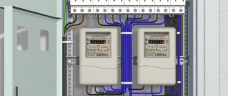
Connection diagram for reed switch water level sensor
Reed switches are low power devices and are unable to switch high currents, so they cannot be used directly to turn a pump off and on. They are usually involved in the low-voltage switching circuit for the operation of a high-power pump relay located in the control cabinet.
The figure shows the simplest circuit with a sensor that controls the drainage pump depending on the water level during pumping, consisting of two reed switches SV1 and SV2.
When the liquid reaches the upper level, the magnet with the float turns on the upper reed switch SV1 and voltage is applied to the relay coil P1. Its contacts close, a parallel connection to the reed switch occurs and the relay is self-capturing.
Voltage is supplied to the coil of a powerful relay in the power supply circuit of the pump, its contacts close and the electric pump begins to work. When the water level drops and the float with the magnet of the lower reed switch SV2 reaches it, it turns on and a positive potential is also applied to the relay coil P1 on the other side, the current stops flowing and relay P1 turns off. This causes a lack of current in the coil of power relay P2 and, as a result, the supply voltage to the electric pump stops.
Rice. 6 Float vertical water level sensors
A similar pump control circuit, placed in the control cabinet, can be used when monitoring the level in a tank with liquid, if the reed switches are swapped, that is, SV2 will be at the top and turn off the pump, and SV1 in the depths of the water tank will turn it on.
Level sensors can be used in everyday life to automate the process when filling large containers with water using electric water pumps. The easiest types of reed switches to install and operate are those produced by industry in the form of vertical floats on rods and horizontal structures.
To automate many production processes, it is necessary to monitor the water level in the tank; the measurement is carried out using a special sensor that gives a signal when the process medium reaches a certain level. It is impossible to do without level meters in everyday life; a striking example of this is the shut-off valve of a toilet cistern or an automatic system for shutting off a well pump. Let's look at the different types of level sensors, their design and operating principle. This information will be useful when choosing a device for a specific task or making a sensor yourself.
Design and principle of operation
The design of measuring devices of this type is determined by the following parameters:
- Functionality, depending on this device, is usually divided into alarms and level meters. The former monitor a specific tank filling point (minimum or maximum), while the latter continuously monitor the level.
- The operating principle can be based on: hydrostatics, electrical conductivity, magnetism, optics, acoustics, etc. Actually, this is the main parameter that determines the scope of application.
- Measuring method (contact or non-contact).
In addition, the design features are determined by the nature of the technological environment. It is one thing to measure the height of drinking water in a tank, and another to check the filling of industrial wastewater tanks. In the latter case, appropriate protection is necessary.
Presence sensors
Another equally important and popular application for capacitance-based sensors is their use to detect someone or something in the control area. The simplest example is turning on the lighting on the landing. Although this far from exhausts the capabilities of such meters. The use of such sensors in security alarm systems is no less in demand. Or counting the number of piece products.
How it works
It was already noted above that the human body has a certain dielectric constant and conductivity.
The figure shows a schematic representation of such a system. There are two electrodes connected to the meter. Each of them has its own capacity, designated C1. As a result, the entire system has a certain resulting capacity.
When a new object, for example a person, appears in the controlled area, the system forms two additional capacitances: Ca - between the electrode and the human body, and Cb - between the person and the ground. The resulting capacity of the entire system will change, and this change can be monitored by the monitoring circuit.
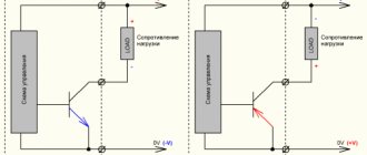
Another way to detect presence
In this case, the effect of increasing the capacity when a foreign object appears in the control zone is also used. Only in this case is the mechanism of active influence on the controlled area applied. For this, a sensor circuit with an active emitter is used.
Such a meter includes a signal generator, a comparator and an amplifier-converter. When the circuit is turned on, an electric field appears in the space in front of the meter. The generator is configured in such a way that it will not start if there are no foreign objects. This is achieved by the fact that the free space is considered to be an unfolded capacitor with a dielectric constant equal to 1. The capacitance value is insufficient to start the generator.
When any materials, objects, or people appear in front of the meter, the dielectric constant of the medium changes (increases), and the capacitance of the capacitor also increases. This causes the generator to start. The amplitude of the vibrations will depend on the distance to the object, its material and dielectric constant.
When the oscillation amplitude reaches a certain value, the comparator is triggered and outputs a signal to the amplifier. Foreign object detected.
This scheme can be used not only in security alarm systems to detect intrusion into a closed area, but also for other purposes. A system for counting the quantity of piece goods, for example, milk packages, cans or any other similar items, can work on this principle.
LC filters as the basis for capacitive measurement
One of the main problems of capacitance measurement is the presence of parasitic noise. Modification of a measuring device that includes a frequency-sensitive component can improve noise immunity. Additionally, a capacitor and an inductor are added to the sensor to form a resonant oscillatory circuit.
Where: a) filter circuit; b) its characteristics.
Although the LC filter architecture is simple, it has several significant advantages when integrated into a capacitance measurement device.
Firstly, the LC resonator provides excellent immunity to electromagnetic interference, and secondly, a noise source operating at certain frequencies can be filtered out by the LC resonator without the use of external circuits. This reduces the complexity of the system and reduces its cost.
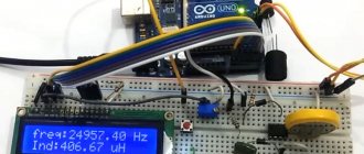
Changing the capacitance of the LC circuit will lead to a shift in the resonant frequency. This principle is used by the FDC2214 in a capacitive-to-digital converter that measures the oscillation frequency of the LC filter. The device outputs a digital value proportional to this frequency. The measurement data can be converted into equivalent capacitance to the downstream microcontroller.
Possible applications of the sensors
The considered capacitive sensors for level, pressure, position and other types of similar products, as well as design features, allow us to draw a conclusion about their versatility. This means they can be used in different areas of industry, regulation and control schemes. As an example, we can name the following areas of the national economy where such meters can be used:
- Oil and gas industry;
- metal mining and processing;
- mining industry;
- agriculture, including livestock and crop production;
- wood processing industry;
- beverage and food production;
- machine tool building and robotic complexes;
- pulp and paper industry;
- chemical industry and others.
The use of capacitive converters allows you to solve a variety of problems. It is simply unrealistic to list them all, but again, as examples, we can list the following options for their use:
- indication of the position of liquids, bulk substances, including products, in a pipe or storage facility, control of their filling;
- alarm for broken wire, tape, or other similar items during winding;
- counting the number of piece products;
- belt tension control;
- use in security systems to detect unauthorized intrusion.
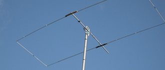
Inclinometers
Devices that have become relatively common only in recent years are small-sized capacitive inclinometers that provide the transmission of an electrical output signal, the magnitude of which is directly proportional to the angle of inclination of the sensor used.
The most common main areas of use of these devices: platform leveling systems, determination of the amount of deflection and technical deformation of various types of support beams, as well as precise control of the slope of automobile and railway tracks at the stage of their construction.
In addition, with the help of such devices, the roll of heavy-duty vehicles and other vehicles, lifts and industrial excavators is determined, as well as the degree of angular movement in relation to especially large agricultural and industrial machines.
Capacitive fuel level sensors are very important in the oil industry. They are even used on supertankers, which transport tens and hundreds of thousands of tons of refined petroleum products in one voyage. These devices are extremely effective even in conditions of the formation of extremely abundant condensation and a high degree of dust in the production area (the same gas sensor).
They also find their application in measuring absolute and relative pressure levels, as well as the thickness of dielectric material, which is extremely important in almost all industries where truly powerful capacitors are used.
Benefits of capacitive sensors
Among the undoubted advantages of such sensors, wherever they are used, be it in Moscow or Antarctica, it is worth noting:
- light weight, dimensions, low power consumption;
- lack of contacts;
- long service life;
- the ability to adapt sensors for use to solve various problems;
- little effort required to move moving parts.
- ease of manufacture, as well as the use of accessible, inexpensive materials for these purposes;
Characteristics of linear displacement sensors
All non-electrical quantities that often need to be controlled in industrial environments are extremely diverse and multifaceted. A significant part of the measures that are subject to strict control are angular and even linear movements of various kinds of surfaces in space. If you use a capacitor that has an absolutely uniform electric field in the working gap, then it is not so difficult to make electronic sensors of the following two types:
- In which the area of the electrodes will be variable.
- Those that have a variable gap between these electrodes.
It is not difficult to understand that the first type is most suitable for recording really large movements, while with the help of the second type one can even notice such body movements in space, the magnitude of which is only a few microns!
Where can I buy
Various touch devices can be purchased at a specialty store. But there is another option that has recently received significant improvements. You no longer need to wait a long time for a parcel from China: the AliExpress online store now offers the opportunity to ship from transshipment warehouses located in various countries. For example, when ordering, you can specify the “Delivery from the Russian Federation” option.
Follow the links and choose:
| Capacitive soil moisture sensor | Capacitive proximity sensor | DC 12V Capacitive Touch Switch |
| High Quality LJC18A3-HZ/BX 1-10mm Capacitive Proximity Sensor | LJC18A3-HZ/BX 1-10mm capacitive proximity sensor | Capacitive Touch DC Switch Button |
Water level sensor assembly
- Attach the Reed switches to the plastic clamp with hot glue, having previously determined the required distance experimentally. Treat the connection with silicone;
- Place the finished bracelet on the coupling. The length of the float holder determines the actuation stroke of the device;
- The float must be heated with a hairdryer and quickly placed on the coupling, then glued and connected with rivets. The clamp should rotate easily around the coupling with reed switches;
- Install the plugs on the float and attach it to the profile with rivets;
- A neodymium magnet is also attached, which should be within the operating distance of the reed switches;
- Drill a hole in the coupling and install the float stopper;
- Place the assembled structure on the pipe and connect the plug and LED indicator.
I am attaching photos of the assembly: