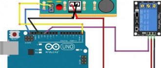
Inductive sensors
In the first part of the article, possible options for sensor outputs were described. There should be no problems connecting sensors with contacts (relay output). But with transistor ones, not everything is so simple. There are many nuances that need to be taken into account: polarity, operating logic, voltage.
As an example, simplified diagrams for connecting sensors with transistor output are shown (Fig. 1) . The load is usually the controller input.
Rice. 1, a - sensor with an NPN output transistor. The common wire is switched, which in this case is the negative wire of the power source. The load (Load) is constantly connected to the “plus” (+V). Here, the active level (discrete “1”) at the sensor output is low (0V), while power is supplied to the load through the opened transistor.
Rice. 1, b - case with a PNP transistor at the output. The load (Load) is constantly connected to “minus” (0V), the supply of discrete “1” (+V) is switched by a transistor. This case is the most common, since in modern electronics it is common to make the negative wire of the power supply common (zero), and activate the inputs of controllers and other recording devices with a positive potential.
The transistor output voltage is typically determined by the supply voltage, which is usually limited within a narrow range. For example, from 18 to 30 V. You can look at this from the other side - now most devices are standardized by voltage.
Next, we move from theory to practical issues.
Transistor sensor outputs: PNP, NPN, NO, NC
Let's break down the possible output options for transistor sensors, which are now available at every step. (at least in my life))
Types of sensors by output polarity
All discrete sensors can have only 3 types of outputs depending on the key (output) element:
Relay.
Everything is clear here. The relay switches the required voltage or one of the power wires. This ensures complete galvanic isolation from the sensor power circuit, which is the main advantage of such a circuit. That is, regardless of the sensor supply voltage, you can turn on/off the load with any voltage. Mainly used in large-sized sensors.
Transistor PNP.
This is a PNP sensor. The output is a PNP transistor, that is, the “positive” wire is switched. The load is constantly connected to “minus”.
A classic circuit based on a PNP transistor, I soldered similar ones back in the 5th grade in a radio club:
Transistor NPN.
At the output there is an NPN transistor, that is, the “negative” or neutral wire is switched. The load is constantly connected to the “plus”.
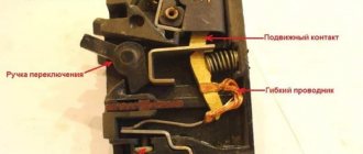
You can clearly understand the difference by understanding the principle of operation and switching circuits of transistors. The following rule will help: Where the emitter is connected, that wire is switched. The other wire is connected to the load permanently.
Below are diagrams for connecting the sensors
, which will clearly show these differences.
For example, a sensor with a transistor output:
In addition to bipolar ones, there may be other types of transistors at the output. But I will keep silent about this in this article.
Many other sensors are discussed using the links at the end of the article.
Types of sensors by output status (NC and NO)
Whatever the sensor, one of its main parameters is the electrical state of the output at the moment when the sensor is not activated (no impact is made on it).
Sensor interchangeability
As I already wrote in the previous part of the article, there are four types of sensors with transistor output, which are divided according to the internal structure and switching circuit: PNP NO; PNP NC; NPN NO; NPN NC.
It happens that the required type of sensor is not at hand, but the equipment must work without downtime! The good news is that the listed types of sensors can be replaced with each other.
This is implemented in the following ways:
- Alteration of the initiation device - the design is mechanically changed. For example, if the NO sensor reacted to the presence of metal, then the NC sensor will react to its absence. If the output is of the same polarity, then neither the program nor the operating algorithm will change.
- Changing the existing sensor switching circuit (we will consider it in more detail below).
- Switching the type of sensor output (if there are such switches on the sensor body).
- Reprogramming the controller program (changing the active input level, changing the program algorithm).
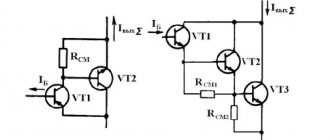
Naturally, manufacturers are silent about such opportunities in order to sell a large number and range of products. Below is an example of how you can replace a PNP sensor with an NPN one by changing the connection diagram (Fig. 2) .
Understanding the operation of these circuits will help you understand the fact that the transistor is a key element that can be represented by ordinary relay contacts.
In Fig. 2, a shows a diagram of a sensor with a normally open PNP type output. When the sensor is not active, its output "contacts" are open and no current flows through them. Conversely, if the contacts are closed, then the flowing current creates a voltage drop across the load.
When activated, voltage (+V) is supplied to the controller input through an open transistor, and it is activated. How can we achieve the same with NPN output?
We look at the changes in the circuit in Fig. 2, b . First of all, the operating mode of the sensor output transistor is ensured. To do this, an additional resistor is added to the circuit; its resistance is usually about 4.7–10 kOhm. Now, when the sensor is not active, voltage (+V) is supplied to the controller input through an additional resistor, and the controller input is activated.
How to repair and check an inductive sensor?
Proximity sensors are practically not subject to repair, since they have a solid body filled with a compound. In addition, most breakdowns are associated with mechanical damage due to careless personnel or shifting of the activator.
To test the sensor electrically, you need to supply power to it, that is, connect it to the circuit, and then activate (initiate). When activated, the indicator should light up. But the indication does not guarantee the correct operation of the inductive sensor. You need to connect the load and measure the voltage across it to be 100% sure.
Device and principle of operation
Inductive sensor LJ12A3-4-Z/BX (D-12mm)
Inductive position sensors, in addition to the electronic comparator, contain the following mandatory components:
- steel case with connector for connecting cord;
- a built-in sensitive element that registers changes in the magnetic field is made in the form of a steel core with a coil;
- executive relay module;
- activation indicator on the LED.
The designs of different models of metal sensors may have some differences. They do not affect the induction sensor itself; the principle of its operation does not change.
Internal structure of an inductive displacement sensor
In accordance with the design of the device, the essence of its operation is described as follows:
- movement of the metal part of the controlled object leads to a change in the inductance of the sensitive element of the sensor;
- the deviation is explained by a distortion of its magnetic field, which results in a change in the parameters of the electrical circuit and its activation (the LED lights up);
- after this, the electronic module is triggered and sends a signal to the actuator;
- When a pulse is received indicating that the movement exceeds the permissible limit, the output (relay) node disconnects the controlled equipment from the network.
Each model has its own displacement sensitivity indicator - displacement gap. For different samples, this parameter varies from 1 micron to 20 millimeters.
Color coding of sensor leads
There is a standard sensor labeling system. All manufacturers currently adhere to it.
- Blue - minus power.
- Brown – plus nutrition.
- Black - exit.
- White – second output, or control input.
However, immediately before installation, it would be useful to make sure that the connection is correct by referring to the connection manual (instructions). In addition, as a rule, the wire colors are indicated on the sensor itself, if its size allows.
Specific manufacturers
Below is my subjective opinion on the sensors that I had to deal with.
"TEKO". For those who choose a domestic manufacturer. This Chelyabinsk company has been around since Soviet times and currently produces a wide variety of sensors. Unfortunately, in my experience, they account for a large number of electrical failures. They also have weak mechanical strength. I hope the company has now improved the quality of its products. The undoubted advantage of this company is the price, which can be 2-3 times lower than imported analogues (with the exception of China). An example of the use of an inductive sensor "Teko" - fig. 4 .
Rice. 4 - Example of using an inductive sensor “TEKO”
In this case, the activator, which passes by the sensor, has moved and broken the original sensor. The solution was to install a Teko sensor with a large response zone.
AUTONICS . The optimal choice in terms of price/quality ratio. This Korean company produces a large number of sensors with good quality. Thanks to modest investments in brand promotion, prices remain very reasonable.
In Fig. Figure 5 shows an example of modernizing the soldering head of a packaging line.
Rice. 5 — An example of upgrading the soldering head of a packaging line
At the top is the Autonics sensor. Previously, an electric limit switch was installed, as in the lower part of the photo. To eliminate problems with contacts, it was decided to install an inductive sensor, which Autonics did an excellent job with and the failures stopped. The completion was the laying of an additional power wire and the manufacture of a mounting plate.
OMRON . This is an old, well-promoted brand, so the price for these sensors is quite high. However, the quality is up to par.
In Fig. 6 - sensors show the position of the gearbox mechanism.
Rice. 6 - The sensor shows the position of the mechanical gearbox.
In most cases, installing sensors from popular brands is impractical, so they are installed in equipment of a high price category.
ALLEN BRADLEY . This American brand is like the Rolls-Royce in the world of engines. The price is very high, but the quality in this particular case let us down: the sensor installed on the lid of the bulk solids bin stopped working (Fig. 7) .
Rice. 7 — Allen Bradley transmitter
It turned out that the problem was in the connector contacts. They were bent and cleaned. In this case, with proper installation, the Teko sensor would do a great job. By the way, the difference in price of these sensors is about 10 times!
It should be said that currently more than 90% of the total number of inductive sensors are replaced by sensors from other manufacturers. There are rarely times when a specific type is needed. As a rule, this is due to the dimensions and installation features. Within one enterprise, it is advisable to choose one manufacturer.
This article is the second part of an article about the types and principles of operation of sensors. For those who haven’t read it, I recommend it, there are a lot of subtleties laid out on the shelves.
Connection diagrams for PNP and NPN sensors
The difference between PNP and NPN sensors is that they switch different poles of the power source. PNP (from the word “Positive”) switches the positive output of the power supply, NPN – negative.
Below, as an example, are diagrams for connecting sensors with a transistor output. Load – as a rule, this is the controller input.
PNP sensor output. The load (Load) is constantly connected to “minus” (0V), the supply of discrete “1” (+V) is switched by a transistor. NO or NC sensor – depends on the control circuit (Main circuit)
NPN sensor output. The load (Load) is constantly connected to the “plus” (+V). Here, the active level (discrete “1”) at the sensor output is low (0V), while the load is supplied with power through the opened transistor.
I urge everyone not to get confused; the operation of these schemes will be described in detail below.
The diagrams below show basically the same thing. Emphasis is placed on the differences in the PNP and NPN output circuits.
Connection diagrams for NPN and PNP sensor outputs
The left figure shows a sensor with an NPN . The common wire is switched, which in this case is the negative wire of the power source.
On the right is the case with a PNP at the output. This case is the most common, since in modern electronics it is customary to make the negative wire of the power supply common, and activate the inputs of controllers and other recording devices with a positive potential.
Sensors with transistor output PNP/NPN, connection diagram, differences and differences
Among all sensors used in industry, discrete ones still prevail, i.e., those with two output signal states - on/off (otherwise - 0 or 1). Basically, such sensors are used to determine certain end positions, and the principle of operation can be any - inductive, optical, capacitive, and so on.
All such sensors have one characteristic in common - output circuitry. There are two main options here:
- Relay output is obviously based on the use of a relay. The sensor's power supply circuit is galvanically isolated from the output, which makes it possible to use such sensors for high-voltage switching.
— transistor output uses a PNP or NPN transistor at the output and connects the positive or negative wire, respectively.
A little theory. PNP and NPN transistors are classified as bipolar and have three terminals: collector, base and emitter. The transistor itself consists of three parts, called regions, separated by two pn junctions. Accordingly, the PNP transistor has two P regions and one N region, and NPN, respectively, two N and one P. The direction of current flow is also different:
— for PNP, when voltage is applied to the emitter, current flows from the emitter to the collector;
- For NPN, applying voltage to the collector causes current to flow from the collector to the emitter.
This necessitates connecting power with direct polarity relative to the common terminals for NPN transistors, and reverse polarity for PNP.
Any bipolar transistor works on the principle of controlling the base current to regulate the current between the emitter and collector. The only difference in the operating principle of PNP and NPN transistors is the polarity of the voltages supplied to the emitter, base and collector. Depending on the implementation of pn junction biases, different operating modes of transistors are possible, but in general, two are used in sensors:
- saturation: direct current flow between emitter and collector (closed contact)
— cutoff: no current between emitter and collector (open contact)
Let's take a closer look at the connection and application features, for example, of inductive sensors with a transistor output. The difference is the switching of different wires of the power supply circuit: PNP connects the plus of the power source, NPN connects the minus. The connection differences are clearly shown below; On the right is a sensor with a PNP output, on the left is an NPN output.
The fundamental difference between PNP and NPN logic
The option with an output based on a PNP transistor is more often used, since circuit design with a common negative wire of the power supply has become more widespread. The output voltage depends on the sensor supply voltage and is usually in a narrow range, for example, 20...28 V.
The choice of sensor based on the type of transistor used is determined primarily by the circuit design of the controller used or other equipment to which the sensor is supposed to be connected. Typically, the documentation for controllers and switching devices indicates which transistor output they allow to use.
Now about compatibility. In general, there are four main types of sensor output:
— PNP NO (NO)
— PNP NC (NZ)
- NPN NO (NO)
— NPN NC (NZ)
In addition to the type of transistor used, the difference also lies in the initial state of the output - it can be in its normal (if the sensor is not activated) state either open (open) or short-circuited (closed). Hence the designations NO (NO) - normally open (normally open) and normally closed (normally closed).
What to do if you need to replace one sensor with another, but it is not possible to install an analogue with identical logic and output circuitry? If only the initial state of the output changes (NO to NC and vice versa), there may be several solutions:
- making changes to the design that initiates the sensor
— making changes to the program (algorithm change)
— switching the output function of the sensor (if possible)
Replacing an optical sensor with a change in the type of transistor used is a larger problem than simply changing the algorithm or shifting some design element. Changing the circuitry of the sensor also entails the need to make significant changes to its connection diagram. Of course, this is not always acceptable, but in some cases it is the only way out.
Replacing the PNP sensor with NPN
Consider the circuit shown above on the left (a sensor with a PNP transistor is taken as an example). In the case of an inactive sensor with a normally open output, no current flows through its output contacts; For a normally closed one, the situation is correspondingly the opposite. Due to the flow of current across the load, a voltage drop is created.
Along with the main (external) load of the sensor, which may be the controller input, there may also be an internal load, but it does not guarantee that the sensor will operate stably. If the sensor has no internal load resistance, such a circuit is called an open collector circuit - it can function exclusively in the presence of an external load.
Let's return to the diagram. Activating a sensor with a PNP output provides +V voltage through a transistor to the controller input. Implementation of this circuit with a sensor having an NPN output requires adding an additional resistor to the circuit (the value of which is usually selected in the range of 4.9-10 kOhm) to ensure the functioning of the transistor. In this case, when the sensor is inactive, the voltage is supplied through the added resistor to the controller input, which makes the circuit, in fact, normally closed. Activating the sensor ensures that there is no signal at the controller input, since the NPN transistor, through which almost all of the additional resistor current passes, bypasses the controller input.
Thus, this approach makes it possible to replace a PNP sensor with an NPN one, provided that sensor rephasing is not a problem. This is acceptable when the sensor acts as a pulse counter - monitoring the number of revolutions, number of parts, etc.
If such a change is not acceptable, and it is necessary to preserve the logic of the system, you can take a more complex path.
Schemes for connecting PNP sensors to a device with an NPN input and vice versa
The bottom line is to add an additional bipolar transistor to the connection circuit, the type of which is selected based on the type of input of the device to which the sensor is connected, as well as two additional load resistances. If a device with an NPN input is used, then an additional transistor is required. Activation of the sensor initiates switching of an external transistor, which already supplies voltage to the input of the device. This circuit, unlike the one discussed earlier, retains the logic of the system, but is more complex to assemble.
Replacing sensors
As I already wrote, there are fundamentally 4 types of sensors with transistor output, which are divided according to the internal structure and switching circuit:
All these types of sensors can be replaced with each other, i.e. they are interchangeable.
This is implemented in the following ways:
- Alteration of the initiation device - the design is mechanically changed.
- Changing the existing sensor connection circuit.
- Switching the type of sensor output (if there are such switches on the sensor body).
- Program reprogramming – changing the active level of a given input, changing the program algorithm.
Below is an example of how you can replace a PNP sensor with an NPN one by changing the connection diagram:
PNP-NPN interchangeability schemes. On the left is the original diagram, on the right is the modified one.
Understanding the operation of these circuits will help you understand the fact that the transistor is a key element that can be represented by ordinary relay contacts (examples are below in the notation).
Connecting transistor sensors
Here I will separately consider such an important practical issue as connecting inductive sensors with transistor output, which are ubiquitous in modern industrial equipment. In addition, real instructions for the sensors and links to examples are provided.
The principle of activation (operation) of sensors can be anything - inductive (proximity), optical (photoelectric), etc.
In the first part, possible options for sensor outputs were described. There should be no problems connecting sensors with contacts (relay output). But with transistor ones and connecting to a controller, not everything is so simple.
For those who are interested, I also recommend my article about parallel connection of transistor outputs.
What's new in the VK SamElectric.ru group?
Subscribe and read the article further:
So, the diagram is on the left. Let's assume that the sensor type is NO. Then (regardless of the type of transistor at the output), when the sensor is not active, its output “contacts” are open and no current flows through them. When the sensor is active, the contacts are closed, with all the ensuing consequences. More precisely, with current flowing through these contacts)). The current flowing creates a voltage drop across the load.
The internal load is shown with a dotted line for a reason. This resistor exists, but its presence does not guarantee stable operation of the sensor; the sensor must be connected to the controller input or other load. The resistance of this input is the main load.
If there is no internal load in the sensor, and the collector “hangs in the air,” then this is called an “open collector circuit.” This circuit ONLY works with a connected load.
So, in a circuit with a PNP output, when activated, voltage (+V) is supplied to the controller input through an open transistor, and it is activated. How can we achieve the same with NPN output?
There are situations when the required sensor is not at hand, and the machine must work “right now”.
We look at the changes in the diagram on the right. First of all, the operating mode of the sensor output transistor is ensured. To do this, an additional resistor is added to the circuit; its resistance is usually about 5.1 - 10 kOhm. Now, when the sensor is not active, voltage (+V) is supplied to the controller input through an additional resistor, and the controller input is activated. When the sensor is active, there is a discrete “0” at the controller input, since the controller input is shunted by an open NPN transistor, and almost all of the additional resistor current passes through this transistor.
Bipolar transistor device
The element was called bipolar because two types of charge carriers take part in its operation: electrons (stable negatively charged elementary particles) and holes (quasiparticles with a positive charge). The operation of a previously developed unipolar (field) device is based on the use of only one of the media. The device has 3 layers, each of which is supplied with voltage:
- emitter;
- base (base plate, plate);
- collector.
Interesting!
Depending on the type of conductivity (electronic or hole) of the layers, NPN (Negative-Positive-Negative) and PNP (Positive-Negative-Positive) devices are distinguished.
Negative is a silicon alloy. It has an excess of negative charge carriers - electrons (n-doped), and positive - an excess of positive “holes” (p-doped).
The base is very thin, represented by a lightly doped semiconductor, so it has strong resistance. The collector is usually wider than the emitter. Therefore, the total area of the base-collector connection is significantly larger than the base-emitter complex. These 2 areas cannot be swapped by changing the polarity. The transistor is not a symmetrical element - this is necessary for its proper operation.
Color coding of sensor leads
There is a standard sensor labeling system. All manufacturers currently adhere to it.
However, before installation, it is a good idea to make sure that the connection is correct by referring to the connection manual (instructions). In addition, as a rule, the wire colors are indicated on the sensor itself, if its size allows.
This is the marking.
- Blue – Minus power
- Brown – Plus
- Black – Output
- White – second output, or control input, see the instructions.
Real sensors
It is problematic to buy sensors, the product is specific, and electricians do not sell these in stores. Alternatively, you can buy them in China, on AliExpress.
Here are the types of optical sensors I encounter in my work.
Thank you all for your attention, I look forward to questions about connecting sensors in the comments!
Option No. 1: use a special converter, for example a USM signal matching device, which is presented in our assortment, or a similar one.
Option No. 2: if you are at least minimally comfortable with a soldering iron, make the converter yourself.
If you have a sensor with a PNP output, but you need NPN, we assemble the following circuit:
Transistor Q1 is any suitable NPN, for example 2SC495, BC445, BD237.
If you have a sensor with an NPN output, but you need a PNP, use the following circuit:
Transistor Q1 - any suitable PNP, for example 2N5401, KT502D.