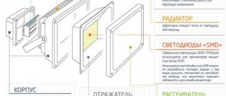
LED matrices are improving every year and recently manufacturers have developed a new type of matrices for spotlights that can be connected directly to a 220 V AC power supply.
Easy to connect, no need for an expensive driver, a number of matrices are available with power from 10 to 50 W. I decided to study the advantages and disadvantages of this type of LED matrices in practice.
About five years ago we had to repair two LED spotlights. In one of them the matrix and driver burned out, and in the second only the driver. One of the two was repaired. The second one, with a burnt-out matrix and driver, has been collecting dust on the shelf ever since. I decided to repair it using a modern LED matrix.
I bought two RoHS F4054 matrices with a power of 10 W for two dollars on Aliexpress, one in reserve, you never know what will happen during testing. By the way, the numbers in the markings after the letter F indicate the width and length of the matrix in millimeters. The purchased matrix had a size of 40×50 mm.
Checking the driver
Let me remind you that the word “driver” is a marketing ploy to designate a current source designed for a specific matrix with a certain current and power.
In order to test the driver without an LED (idle, without load), simply apply 220V to its input. A constant voltage should appear at the output, a value slightly greater than the upper limit indicated on the block.
For example, if the range of 28-38 V is indicated on the driver unit, then when it is turned on idle, the output voltage will be approximately 40V. This is explained by the principle of operation of the circuit - in order to maintain the current in a given range of ±5%, when the load resistance increases (idle = infinity), the voltage must also increase. Naturally, not to infinity, but to some upper limit.
However, this test method does not allow us to judge whether the LED driver is 100% serviceable.
The fact is that there are serviceable units that, when turned on idle, without load, either will not start at all, or will produce something unclear.
I suggest connecting a load resistor to the output of the LED driver to provide it with the desired operating mode. How to choose a resistor - according to Uncle Ohm's law, looking at what is written on the driver.
LED – driver 20 W. Stable output current 600 mA, voltage 23-35 V.
For example, if Output 23-35 VDC 600 mA is written, then the resistor resistance will be from 23/0.6=38 Ohms to 35/0.6=58 Ohms. We choose from a range of resistances: 39, 43, 47, 51, 56 Ohms. The power must be appropriate. But if you take 5 W, then it will be enough for a few seconds to check.
Attention! The driver output, as a rule, is galvanically isolated from the 220V network. However, you should be careful - cheap circuits may not have a transformer!
If, when connecting the required resistor, the output voltage is within the specified limits, we conclude that the LED driver is working.
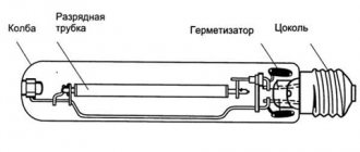
Operating principle and diagram
The voltage is supplied to the converter input through a fuse (or motion sensor relay). It is rectified by a diode bridge and smoothed by a capacitor. The current output from the capacitor is constant. Next, the voltage is supplied through a resistor to the zener diode and transformer.
From the zener diode comes 9 V, which is necessary for the operation of the converter, from the transformer - high-frequency pulses to the field-effect transistor. In a field-effect transistor, the resistance is reduced to almost zero; when current passes through the primary winding of the transformer, a voltage is created in the second winding. After rectification by a diode and smoothing by a capacitor, current enters the matrix and the diodes light up.
This is a standard diagram, it may vary depending on models and manufacturers.
What to do if the power of the LED module is unknown
There are situations when there is an LED chip, but its power, current and voltage are unknown. Accordingly, it is difficult to buy it, and if it is working, it is not clear how to choose an adapter.
This was a big problem for me until I figured it out. I am sharing with you how to determine from the appearance of an LED assembly what voltage, power and current it is.
For example, we have a spotlight with the following LED assembly:
9 diodes. 10 W, 300 mA. In fact - 9 W, but this is within the margin of error.
The fact is that LED matrixes of floodlights use 1 W diodes. The current of such diodes is 300...330 mA. Naturally, all this is approximately, within the margin of error, but in practice it works accurately.
In this matrix, 9 diodes are connected in series, they have one current (300 mA), and a voltage of 3 Volts. As a result, the total voltage is 3x9 = 27 Volts. For such matrices, you need a driver with a current of 300 mA, a voltage of approximately 27V (usually from 20 to 36V). The power of one such diode, as I said, is about 9 W, but for marketing purposes this spotlight will have a power of 10 W.
The 10 W example is a bit atypical due to the special arrangement of the LEDs.
Another example, more typical:
LED assembly for 20 W floodlight
You already guessed that two horizontal rows of dots of 10 pieces each are LEDs. One strip is, offhand, 30 Volts, current 300 mA. Two strips connected in parallel - voltage 30 V, current twice as much, 600 mA.
A couple more examples:
5 rows (zig-zag) of 10 LEDs.
Total - 50 W, current 300x5 = 1500 mA.
Matrix 7 rows of 10 LEDs
Total - 70 W, 300x7 = 2100 mA.
I think there is no point in continuing, everything is already clear.
The situation is slightly different with LED modules based on discrete diodes. According to my calculations, one diode there usually has a power of 0.5 W. Here is an example of a GT50390 matrix installed in a 50 W floodlight:
LED floodlight Navigator, 50 W. LED module GT50390 – 90 discrete diodes
If, according to my assumptions, the power of such diodes is 0.5 W, then the power of the entire module should be 45 W. Its circuit will be the same, 9 lines of 10 diodes each with a total voltage of about 30 V. The operating current of one diode is 150...170 mA, the total current of the module is 1350...1500.
Anyone who has other thoughts on this matter is welcome to comment!
Causes of failure
Possible reasons for the spotlight not working properly:
- Unstable electrical network (voltage drops beyond the operating current);
- short circuit of a phase to the device body or to neutral;
- incorrect connection;
- overvoltage;
- use of overcurrents.
In the event of these violations, the board on which drivers, voltage and current converters are installed, supplying power to the matrix crystals, may fail. Damage to 3 to 5 crystals in a floodlight matrix is allowed. If the number of faulty crystals is greater, the spotlight will not be able to operate with a sufficient degree of functionality and the matrix will need to be replaced.
LED spotlight driver repair
It is better to start repairs by searching for the electrical circuit of the LED driver.
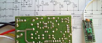
As a rule, LED spotlight drivers are built on a specialized MT7930 chip. In the article about the Design of Spotlights, I gave a photo of a board (not waterproof) based on this microcircuit, once again:
LED floodlight Navigator, 50 W. Driver. GT503F board
LED floodlight Navigator, 50 W. Driver. View from the soldering side
Attention! Information on driver circuits and a little more on repairs is included in a separate article!
Diagnostics
Before starting repairs with your own hands, you need to check the wiring for kinks and burnt insulation to make sure that there are no wire breaks. It is also advisable to carefully inspect the case in order to identify cracks, deformations, and chips. It may turn out that the problem will be solved by eliminating these problems; you will not need to think about how to disassemble the LED spotlight and determine why it stopped working.
Diagnostic sequence after opening the case:
- checking the integrity of the lamps in the module;
- measuring the input voltage with a multimeter (must be 220 V)
- output voltage measurement (DC 12 W).
If there is no voltage at the input, you need to look for burnt-out driver parts, oxidized contacts, or cracks in the coating. If the board and the elements soldered to it are in order, the functionality of the module must be checked. It stops functioning if several LEDs burn out.
LED replacement
There are no special tricks when replacing the LED matrix, but you need to pay attention to the following things.
- Carefully remove old heat-conducting paste,
- Apply thermal conductive paste to the new LED. It is best to do this with a plastic card,
- fix the diode evenly, without distortions,
- remove excess paste,
- do not confuse the polarity,
- Do not overheat when soldering.
The reverse side of the LED matrix, on which thermal conductive paste is applied during installation
When repairing an LED module consisting of discrete diodes, first of all you need to pay attention to the integrity of the soldering. And then check each diode by applying a voltage of 2.3 - 2.8 V to it.
Useful tips
- Do not overheat the surface. Soldering time is 2 seconds. Overheating the matrix will destroy the LED crystals.
- The temperature of the soldering iron tip should be optimal. A cold tip will not allow you to quickly solder, but its temperature will destroy the matrix crystals in the same way as an overheated one.
- Use an antistatic wrist strap when disassembling electronic devices.
- Degrease and wash with alcohol.
- Pay attention to the polarity of semiconductor elements and electrolytic capacitors. The wires are “ringed” to see if there is contact from the socket to the board.
- Repairing floodlights of any power requires the same knowledge.
- Read the floodlight instructions before use.
To repair a spotlight, you need basic knowledge in the field of electrical engineering, skills in handling a soldering iron, and measuring equipment. Requires the ability to read electrical diagrams and a certain level of accuracy.
To extend the life of the spotlight you need to:
- create a mode of high-quality heat removal (gaps between the housing and the wall, absence of heating elements near the spotlight);
- periodically wipe the spotlight's optics (dirt will degrade the light output and, when heated, will overheat the spotlight);
- monitor the tightness of the spotlight (moisture that gets inside the device will invariably oxidize the elements, create unnecessary contacts and destroy the necessary ones).
Verification methods
The LED has its own electrical parameters, this is the maximum operating current, as well as the forward voltage drop. Manufacturers indicate the value of the first parameter individually for each product, and the second is 1.8 - 2.2 volts for orange, yellow and red diodes. For white, green and blue 3 - 3.6 volts. Checking these parameter values if you have a multimeter is not difficult.
Another way to check the performance of a LED diode is to supply it with power from several parallel-connected AA batteries or one Krona battery. Based on this method, you can independently make a universal tester for LEDs using improvised elements. The detailed process for determining performance is shown in the video.
You can determine a faulty LED by using old mobile phone chargers as a current source for testing. To do this, you need to cut off the plug connecting to the phone and strip the wires. The red wire is a plus, it needs to be pressed to the anode, the black wire is a minus, it is connected to the cathode. If the power supply voltage is sufficient, it should light up.
To check some diodes, the voltage from charging the phone may not be enough, then you can try to check using a more powerful device, for example charging from a flashlight. In this way, it is quite possible to check the performance of the diodes in the LED lamp. How to do this, watch the video.
How to ring without soldering
To check the LED without desoldering, you need to analyze the device circuit. If there are no circuits parallel to the diode, you can ring it without desoldering it. Parallel circuits may influence the result.
You need to solder sharp steel needles onto the multimeter probes. The entire needle except the tip and probe must be insulated, for example, with heat-shrinkable tubing. Using a probe with a needle, pierce the layer of protective varnish until it comes into contact with the diode terminal on the case or the contact pad on the board. Measuring resistance in the forward and reverse directions shows the performance of the device. Direct resistance is tens to hundreds of Ohms. The opposite is hundreds of kiloohms or more.