The secret to longevity of LED lamps
I noticed this thing. LED light bulbs are positioned on the market as the most reliable, economical and durable. Manufacturers promise that they will last 10 years. In fact, they work exactly until the warranty expires. Although they could shine longer.
The Chinese save on everything they can - driver components, LEDs, board and case materials. As a result, the light bulbs become overloaded and overheat. LEDs are operated in extreme conditions!
I noticed this when another light bulb stopped shining after a year. I decided to take it apart and see what the problem was. It turned out that the resistors and capacitors were selected so that the LEDs worked at their full power. Not surprisingly, one of them burned down.
Assembly process
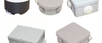
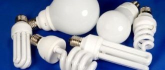
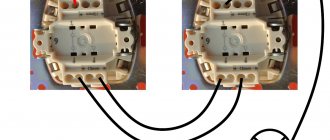
First of all, the fluorescent lamp must be disassembled. In this design we are interested in the base with a reflector. This is where all the necessary parts are located, which are combined into an electrical circuit that includes the lamp. It must be disassembled carefully, without damaging those very parts.
Please note that the CFL circuit itself is not suitable for an LED lamp. Therefore it must be disassembled
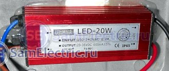
We will need a fuse from the base; there is no need to remove it from the circuit. Next, a diode will also come in handy, by the way, its brand is 1N4007. You will have to add any electrolyte to the new circuit, the main thing is that its voltage is not lower than 50 volts and its capacity is not less than 100 μF. And one more detail that comes in handy is a 1 µF capacitor with a voltage of 630 volts.
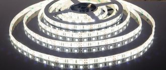
Of course, you will need the LEDs themselves. They can be taken from an LED strip, which is cut into sections containing three LEDs. This segment is powered by a voltage of 12 volts. In general, you will need four pieces of LED strip.
The figure below shows a diagram of the assembly of all parts.
To prevent them from dangling in the base itself, you need to attach them using any adhesive. It would be better if it was super glue. But you need to build a frame under the pieces of LED strip. In principle, it can be any easily bendable dense material. Ideally, it will not be metal or any other conductive structure.
Experienced craftsmen use foam board for such tasks because it is easy to process. It must be rolled into a tube so that the diameter of the extension structure is slightly smaller than the diameter of the base. This is done so that the foam board fits into the base, where it is also glued.
The diagram above clearly shows that the tape segments are connected in series. But in the design they will be located one above the other. By the way, you can increase the number of segments (levels) without any problems. You just have to select the capacitor and electrolyte to match the power of the entire lamp, increasing the capacity.
By the way, it is better to glue the tape to the base with liquid nails, because using this glue you can align the location of the LEDs. After all, liquid nails take longer to dry than super glue. In addition, the tape itself can be filled with liquid nails, leaving only LEDs outside, giving a unique design to the lamp. In this case, the glue will also play another function - protective, so that the tape is not damaged under mechanical loads.
The most amazing thing is that such a lamp, assembled with your own hands, can work even at a voltage of 40 volts. But that is not all.
- At a voltage of 220 volts, each segment of the LED strip will have a voltage of 11.5 volts.
- When the voltage increases to 240 volts, the voltage on the segments will be 12 volts.
Hence the conclusion - voltage drops are not dangerous for such a homemade LED lamp. By the way, the brightness of such a light source is quite decent. For example, if you use 5050 SMD tape for assembly, then each LED emits a luminous flux of 10-15 lumens. Multiply this figure by the number of LEDs, and in total you will get the total brightness of the lamp, which will vary in the range of 120-180 lumens. And this is decent brightness.
Of course, this type of light source also has a drawback. This is an open type electrical connection between the LEDs and the 220 volt network
Therefore, such an LED lamp must be handled very carefully, adhering to standard safety standards
Disassembly
It was decided to extend the life of the light bulb in the most barbaric way. I'll start from the beginning - with disassembly.
- Take a sharp knife. We wear gloves to avoid cutting ourselves.
- We put the light bulb on the table.
- We insert the knife blade into the microslot between the diffuser and the middle part of the lamp.
- They are connected by some kind of sealant.
- Lightly press the knife on top and roll the lamp over.
- A couple of minutes, and the sealant is cut off, and the shade comes out of the latches of the middle part.
- Under the cover, the LEDs connected in series on the board will appear.
- Unscrew 2 screws and unsolder. Cut hot melt glue in a circle.
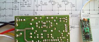
- We take out the board by prying it with a knife.
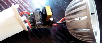
- Behind it is a driver that can be pulled out with your fingers. That's it, the light bulb is disassembled.
It is structured very simply:
Recovery
This video inspired me to make my own light bulb:
We recommend: Sterilizing jars in the microwave: how to prepare containers for sealing in 5 minutes?
- We find a burnt out LED (or several).
- They are usually marked with a black dot. In my case, the entire LED was burnt out.
- We paint out the fire victim with a knife or screwdriver.
- We drip flux onto the exposed contact and apply a drop of solder.
This way we restore the circuit and the light bulb starts working again. But! There's one catch. The voltage then increases and the LEDs will light up one after the other. Perhaps the light bulb will work for another month. Or maybe just one day.
Brightening Up
At the stage of replacing the resistor, one could stop - put the lamp back together, glue (tape) the diffuser... But the light seemed not bright enough to me. The question was how to fix this. I took the simplest route.
To increase the brightness of the light bulb, I took an old CD. I modified it a little and got a powerful reflector.
- Widened the central hole of the disk. To do this, I used a 35-point carpenter's pen. You can cut a hole with any other handy tool. Not the point.
- I glued the board with LEDs to the disk. I took hot glue. I spread it on the reflective side of the CD (around the hole). I pressed the board with its back.
- I reassembled the light bulb in reverse order. Where necessary, we solder the contacts. We do not change places of wires, even if the length allows. The light will flicker.
- I taped the seam where the case meets the CD so that the structure is strong and does not fall apart. The diffuser was thrown away.
Bottom line. A non-working LED light bulb turned into a kind of mini-spotlight. It’s uncomfortable to look at, but the garage is 200% illuminated! Of course, this option is not suitable for home. As well as for the street (damp rooms). There, brightness will have to be sacrificed for the sake of aesthetics and safety.
We recommend: Is it necessary to lubricate a zipper if it doesn’t fasten well or sticks? Saving the castle
I foresee that many will say, why bother repairing and extending the life of LED lamps? Today the price for them is very affordable. Everyone can afford to throw away the old one and buy a new one. But out of principle, I decided to get the most out of it. I am one hundred percent satisfied with the result. The garage is as bright as day. In 3 years not a single LED has burned out. The lamp has become twice as bright and lasts three times longer (and this is not the limit)!
Common and differential mode
Most LED users are probably familiar with the scenarios outlined above. Before exploring further situations that cause EOS, it is important to understand industry regulations and protection classes.
The International Electrotechnical Commission (IEC) and IEC 61140:2016 define the rules for protecting people from electric shock. Depending on the country and product type, there are different insulation level requirements for devices sold in each market.
The most commonly used insulation classifications are Class I and Class II. Class I luminaires must have a housing connected to electrical ground using a special cable. Class II luminaires, on the other hand, are designed to provide the required level of safety without any electrical grounding.
| Protection class symbols | |
| Class I | Class II |
These two different classifications allow solid-state lighting products to behave very differently when exposed to external influences. In general, if electrical grounding is done in an effective and reliable manner, Class I fixtures are less likely to suffer from EOS failure, but in reality both types of fixtures must be designed effectively to prevent EOS failure. Another important regulation to consider is IEC60598-1:2014, which specifies general requirements and tests for luminaires, including solid-state luminaires. This 2014 edition replaces the 2008 version and contains corresponding changes for Class II products.
Clause 10; Section 4 of IEC 60598-1:2014 “Design” deals with double insulated class II luminaires. Sub-clause 4 (IV.10.4) of the chapter specifies the protective impedance device, which states that the accessible conductive parts, separated by double insulation, can act as a conductive bridge using resistors or capacitors Y2. They must consist of at least two separate components with the same rating.
These components must comply with IEC standards. Class II luminaires allow the addition of special components that connect the LED boards to the luminaire body. This allows you to analyze what the LED circuit looks like during fast voltage transients. Figure 8 shows two LEDs in series with a simple model showing the LED and its built-in ESD shield. This model does not account for all parasitic components or the influence of the LED thermal pad. The thermal pad is a vital pad that allows the LED to efficiently transfer heat from the source (connection) to the air through its many metal parts.
Figure 8. A simple model of two LEDs connected in series with ESD protection.
For very good heat transfer, the thermal pad must be connected to a very large copper area on the PCB. This distributes the heat horizontally and then effectively transfers it vertically to the aluminum layer of the PCB due to its large transfer area. Two metals separated by an insulator create a capacitor, meaning that PCBs are the capacitors to consider in this particular analysis. This parasitic capacitance can be large or small depending on the PCB design and material used. It cannot be ignored and it is important to understand how to manage it to avoid problems with EOS.
LED and TVS can be simulated in a very complex way, and for people who like to spend hours in simulation, this is a great way to have fun. For the purposes of this article, only a simplified model is used with a capacitor connected electronically in parallel with other components, as shown in Figure 9. Because of the stray capacitance between each thermal pad and ground, it is important to understand how to connect them. There are two options: keep them separate or connect them.
Figure 9: Simplified model of LED and TVS with capacitor
There is also the option of leaving them electrically floating or connecting them to electrical voltage potential. Leaving them floating is a relatively unsafe option, since any common mode voltage is applied directly between the thermal pad and the LED's electrical pads - anode and cathode. This creates a fatal EOS once the voltage drop between the points marked by the blue arrows (Figure 10) exceeds the insulation of the LED stack. In terms of LED housing material, ceramic provides much better insulation than plastic, and depending on the pad spacing, it is possible to have package insulation voltages ranging from several tens to hundreds of volts. In either case, common mode signals can easily reach thousands of volts, thereby creating electrical overvoltage across the LEDs.
Figure 10: Disabling LEDs and TVS is a relatively unsafe option.
Connecting the LED thermal pad to the voltage reference protects the LED from EOS generated by common mode voltage. The signal follows the path to ground through the stray capacitance of the thermocouple, and the voltage across the LED block is limited. Now the need to connect the thermal pads to some electrical potential is obvious, but it is still possible to leave them separately or connect them all.
Figure 11 shows a luminaire circuit energized by differential mode. The red arrow shows the direction of the voltage signal for a positive spike, and the blue arrow for a negative spike. For the purposes of this discussion, the connection of the thermal pad to the anode as well as its connection to the cathode will be considered.
Figure 11: Fixture voltage caused by differential mode (red arrow shows the direction of the voltage signal for a positive surge and blue arrow for a negative surge)
In the event of a positive voltage surge when the temperature sensor is connected to the anode, the voltage will be split between the standard path through the LED string and the stray capacitance between the temperature sensor and ground. The separation factor is determined by the ratio of the LED path impedance to ground and the first parasitic capacitance of the thermal pad. Obviously, when connecting a thermocouple, the parasitic capacitance is n times greater (where n is the number of LEDs), and the impedance is n times less - absorbing most of the voltage.
This means that it is better to connect all the thermal pads rather than leaving them separately. In the case of a negative voltage signal, the entire signal will pass through the CLED, polarizing the LED in the opposite direction. The impedance of CLED is quite high and therefore the reverse voltage drop will also be quite high. The ESD TVS contributes to signal clipping, but since the voltage is higher in the average energy, the EOS LED is damaged by this reverse polarization.
When the signal appears after the first LED, it finds the stray capacitance of the thermocouple to reach electrical ground. The other LEDs on the string become energized, but less and less as each C-thermal pad in the series absorbs some of the voltage signal.
When the thermal pads are connected to the cathode, the positive voltage passes completely through the first LED, damaging it more than in the previous case with the anode connection. However, in the case of negative voltage, the latest LED in the series is less stressed.
Through this first analysis, the LED thermal pad should be connected all together, and then connected at the anode for positive voltage and at the cathode for negative voltage. There is no way to know what type of stress (positive or negative) a luminaire is experiencing; therefore, the best configuration is a symmetrical one, which divides the LED string into two groups with a mirror configuration (Figure 12). The LED thermal pad on the positive side should be connected to the anode, and on the negative side to the cathode.
Figure 12: Dividing the LED string into two groups with a mirror configuration is the best configuration since no one knows what type of voltage (positive or negative) will occur
To further improve the protection of this strong solution, two additional capacitors CP and CN are added on the positive and negative LED groups. Thermocouple and CP and CN areas must be designed and selected properly, but this is only possible when working on the customer's physical loop. It should not be forgotten that IEC 60598-1:2014 allows the use of proper components to connect the luminaire housing to the positive or negative terminals of the power supply output. This will further reduce the potential impact of EOS on LEDs.