Sometimes it becomes necessary to connect a regular, low-power LED to an alternating mains voltage of 220 volts as an indicator light. It would seem that there is nothing simpler than taking and placing a regular resistor in series with the LED, which would limit the current in a given circuit. But it's not that simple. In this article, let’s look at the most common options for such a connection, after which you can choose the best scheme, taking into account the existing advantages and disadvantages.
220V network indicators on LEDs, replacement for neon indicator lights
Schematic diagrams of simple indicators of the presence of a 220V network on LEDs, we replace old neon indicator lamps with LEDs.
In electrical equipment, neon indicator lamps are widely used to indicate that the equipment is turned on. In most cases, the circuit is as in Figure 1. That is, a neon lamp is connected to an alternating current network through a resistor with a resistance of 150-200 kioles. The breakdown threshold of a neon lamp is below 220V, so it easily breaks through and glows. And the resistor limits the current through it so that it does not explode from excess current.
There are also neon lamps with built-in current-limiting resistors; in such circuits, it seems as if the neon lamp is connected to the network without a resistor. In fact, the resistor is hidden in its base or in its lead wire.
The disadvantage of neon indicator lamps is their weak glow and only pink color, and the fact that they are glass. Plus, neon lamps are now less common on sale than LEDs. It is clear that there is a temptation to make a similar power indicator, but on an LED, especially since LEDs come in different colors and are much brighter than “neons”, and there is no glass.
But, LED is a low-voltage device. The forward voltage is usually no more than 3V, and the reverse voltage is also very low. Even if you replace a neon lamp with an LED, it will fail due to the excess reverse voltage at the negative half-wave of the mains voltage.
Rice. 1. Typical diagram for connecting a neon lamp to a 220V network.
However, there are two-color two-terminal LEDs. The housing of such an LED contains two multi-colored LEDs connected back-to-back in parallel. Such an LED can be connected in almost the same way as a neon lamp (Fig. 2), only take a resistor with a lower resistance, because for good brightness more current must flow through the LED than through a neon lamp.
Rice. 2. Diagram of a 220V network indicator on a two-color LED.
In this circuit, one half of the two-color LED HL1 operates on one half-wave, and the other half on the other half-wave of the mains voltage. As a result, the reverse voltage on the LED does not exceed the forward voltage. The only drawback is the color. He is yellow. Because there are usually two colors - red and green, but they burn almost simultaneously, so it visually looks like yellow.
Resistor R1 in the circuit in Figure 2 has a lower resistance than with a neon lamp, and more thermal power is generated on it. You can completely get rid of parasitic thermal power if you replace the resistor with a capacitor (Fig. 3). The forward current through the LED is limited by the reactance of the capacitor, and no heat is generated across it.
Rice. 3. Diagram of a 220V network indicator using a two-color LED and a capacitor.
Figures 4 and 5 show a circuit of a power-on indicator on two LEDs connected back-to-back. This is almost the same as in Fig. 3 and 4, but the LEDs are separate for each half-cycle of the mains voltage. LEDs can be either the same color or different.
Rice. 4. 220V network indicator circuit with two LEDs.
Rice. 5. Diagram of a 220V network indicator with two LEDs and a capacitor.
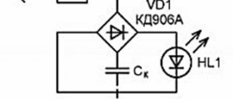
But, if you only need one LED, the second one can be replaced with a regular diode, for example, 1N4148 (Fig. 6 and 7). And there is nothing wrong with the fact that this LED is not designed for mains voltage. Because the reverse voltage across it will not exceed the forward voltage of the LED.
Rice. 6. 220V network indicator circuit with LED and diode.
Rice. 2. Diagram of a 220V network indicator with one LED and a capacitor.
In the circuits, two-color LEDs of the L-53SRGW type and single-color LEDs of the AL307 type were tested. Of course, you can use any other similar indicator LEDs. Resistors and capacitors can also be of other sizes - it all depends on how much current needs to be passed through the LED.
- PCBWay - only $5 for 10 PCBs, first order FREE for new customers.
- PCB assembly from $30 + FREE shipping worldwide + stencil.
- Open Source Projects - Access thousands of open source projects in the PCBWay community!
I really don’t recommend circuits with ballast capacitors. At the moment of switching on, a current surge occurs, and the diodes very often burn. Tested in practice.
You need to know this
The main thing is to remember safety precautions. The presented circuits are powered by 220 V AC, and therefore require special attention during assembly.
Connecting the LED to the network must be carried out in strict accordance with the circuit diagram. Deviation from the diagram or negligence can lead to a short circuit or failure of individual parts.
When you turn it on for the first time, it is recommended to let the assembly work for a while to make sure it is stable and does not overheat the elements.
To increase the reliability of the device, it is recommended to use previously tested parts with a margin of maximum permissible voltage and power values.
You should carefully assemble transformerless power supplies and remember that they do not have galvanic isolation from the network. The finished circuit must be reliably isolated from adjacent metal parts and protected from accidental contact. It can only be dismantled with the power supply switched off.
Purpose of elements and principle of operation of the circuit
Many readers have LED light switches installed in their homes. The LED backlight circuit looks like this:
- A chain consisting of a quenching resistor, an LED and a simple silicon diode is switched on parallel to the switch contact.
- When the switch is open, electric current flows through a quenching (current-limiting) resistor, back-to-back LEDs and an incandescent lamp.
- During one of the half-waves, when a positive voltage is applied to the anode of the LED, the light-emitting diode glows. This not only provides illumination of the switch, but also provides LED voltage indication.
If we remove the switch, light bulb and wires from the circuit, we are left with a chain consisting of a resistor and two diodes. This chain is the simplest indicator (pointer) of 220 V alternating current.
Let us dwell in more detail on the purpose of the circuit elements. We indicated above that the operating current of the signal LED is about 10-15 mA. It is clear that when a light-emitting diode is directly connected to a 220 V network, a current will flow through it many times greater than the maximum permissible value. In order to limit the current of the LED, a quenching resistor is connected in series with it. You can calculate the resistor value using the formula:
- U max – maximum measured voltage;
- U led – voltage drop across the LED;
- I led – operating current of the light-emitting diode.
Having performed the simplest calculation, for a 240 V network we get the value of resistor R1 equal to 15-18 kOhm. For a 380 V network, you need to use a resistor with a resistance of 27 kOhm.
The silicon diode performs the function of overvoltage protection. If it is missing, with a negative half-wave U, the locked LED will drop 220 V or 380 V. Most light-emitting diodes are not designed for such reverse voltage. Because of this, breakdown of the pn junction of the LED may occur. When a silicon diode is connected back-to-back, during the negative half-wave it will be open and U on the LED will not exceed 0.7 V. The LED will be reliably protected from high reverse voltage.
Based on the considered circuit, you can make a voltage indicator of 220/380 V. It is enough to supplement the radio elements with two probes and place them in a suitable housing. To make the indicator body, a large marker or thick felt-tip pen is suitable. You can place radio components on a homemade printed circuit board or make connections using a hinged method.
A hole is made in the marker into which an LED is inserted. A metal probe is attached to one end of the body. A wire is passed through the second end of the housing, going to the second probe or an insulated alligator clip.
Despite the simplicity of the design, the device will allow you to check the presence of voltage at the output of a circuit breaker or in a socket, and find a blown fuse in the distribution board. Note that the above indicator diagram is also used in industrial products.
The nuances of connecting to a 220 Volt network
Scheme for connecting an LED to a 220V network
When using various schemes for connecting an LED to a 220V network, some nuances are possible, taking into account which will help to avoid basic errors in switching electrical circuits. They are mainly related to the amount of current flowing through the circuit when power is applied to it. To understand them, you will need to consider a simple device such as lighting for decoration, consisting of a whole set of LED elements or a regular lamp based on them.
Considerable attention is paid to the features of the processes occurring in the switch at the moment of power supply. To ensure a “soft” switching mode, a quenching resistor and an LED indicator indicating the on state will need to be soldered in parallel to its contacts.
The resistance value is selected using the methods described earlier.
Only after the switch with a resistor in the circuit is the strip itself with chips of LED elements located. It does not provide protective diodes, so the value of the quenching resistor is selected based on the current flowing through the circuit; it should not exceed a value of about 1 mA.
The LED light bulb in this circuit acts as a load, further limiting the current. Due to its small size, it will glow very dimly, but this is quite enough for night mode. When the reverse half-wave is applied, the voltage is partially extinguished across the resistor, which protects the diode from unwanted breakdown.
AC voltage indicator 220 V
Let's consider the first, simplest version of a network indicator on an LED. It is used in screwdrivers to find the 220 V phase. To implement it we will need:
You can choose absolutely any LED (HL). The characteristics of the diode (VD) should be approximately as follows: forward voltage, with a forward current of 10-100 mA - 1-1.1 V. Reverse voltage 30-75 V. Resistor (R) must have a resistance of at least 100 kOhm, but not more than 150 kOhm, otherwise the brightness of the indicator will decrease. Such a device can be made independently in a hinged form, even without the use of a printed circuit board.
The circuit of a primitive current indicator will look similar, only it is necessary to use capacitance.
DC Voltage Check
Often there is a need to ring the low-voltage circuit of household appliances, or check the integrity of a connection, for example, a wire from headphones.
As a current limiter, you can use a low-power incandescent lamp or a 50-100 Ohm resistor. Depending on the polarity of the connection, the corresponding diode lights up. This option is suitable for circuits up to 12V. For higher voltages, you will need to increase the limiting resistor.
AC and DC voltage indicator up to 600 V
The next option is a slightly more complex system, due to the presence in the circuit, in addition to the elements already known to us, of two transistors and a capacitance. But the versatility of this indicator will pleasantly surprise you. It can safely check the presence of voltage from 5 to 600 V, both direct and alternating.
The main element of the voltage indicator circuit is a field-effect transistor (VT2). The threshold voltage value that will allow the indicator to operate is fixed by the gate-source potential difference, and the maximum possible voltage determines the drop at the drain-source. It functions as a current stabilizer. Feedback is provided through a bipolar transistor (VT1) to maintain the set value.
The operating principle of the LED indicator is as follows. When a potential difference is applied to the input, a current will arise in the circuit, the value of which is determined by the resistance (R2) and the voltage of the base-emitter junction of the bipolar transistor (VT1). In order for a weak LED to light up, a stabilization current of 100 μA is sufficient. To do this, the resistance (R2) should be 500-600 Ohms, if the base-emitter voltage is approximately 0.5 V. A capacitor (C) is required to be non-polar, with a capacity of 0.1 μF, it serves as protection for the LED from current surges.
We select a resistor (R1) with a value of 1 MOhm; it acts as a load for the bipolar transistor (VT1). The functions of the diode (VD) in the case of DC voltage indication are pole testing and protection. And to check the alternating voltage, it plays the role of a rectifier, cutting off the negative half-wave. Its reverse voltage must be at least 600 V. As for the LED (HL), choose a super-bright one so that its glow at minimal currents is noticeable.
220V flashing LED circuit
And this circuit allows the LED not just to glow, but to blink, which is much more informative and beautiful. Moreover, we put the most common LED indicator here – non-blinking. To do this you need only 5 radio components.
Here, the mains voltage of 220 volts through a diode and a 200-300 kOhm resistor charges an electrolytic capacitor of 20 uF 100 V, and from it a constant voltage periodically opens the dynistor DB3 , causing the LED to flash. The flash frequency will be determined by the capacitance, and the brightness by the resistance of the resistor.
LED Power Questions
- LED STROBOSCOPE ON MICROCONTROLLER
- SMART LED FLASHLIGHT
- HOMEMADE LIGHT FOR SHOOTING
- LED DRIVER FOR HV9910
Indicator for microcircuits - logic probe
Having learned how to create a simple electrician's probe with your own hands, you can also make a simple logic probe based on LED, which will help you find faults in digital devices.
Logic probes have been around since the early days of computing. With their help, specialists analyzed the logical levels at the inputs and outputs of digital microcircuits. The high level (voltage) at the output of the logic element is assigned the value of logical “one”, and the low level is assigned the value of logical “zero”. By comparing the levels at the input and output of a digital microcircuit, you can judge its serviceability.
To indicate “0” or “1”, two LEDs are sufficient. Therefore, LED logic probes have a simple design. To assemble a simple logic probe you will need:
- 2 transistors VT1 and VT2 npn structures;
- 2 light emitting diodes;
- several resistors.
Transistors are used to assemble 2 amplification stages with a common emitter. The amplification stages must be directly coupled. Red and green LEDs are included in the transistor collector circuit.
The logic probe works as follows:
- When a logical one is applied to the input of the probe, transistor VT1 opens and the red LED lights up. In this case, VT2 is locked and the green LED does not light up.
- When a logical zero is applied to the input, VT1 is locked, while transistor VT2 opens and the green LED lights up.
If the output of the device being tested alternates logical “0” and “1” at high speed, then it will visually appear that both LEDs are lit at the same time.
The considered probe can be used to test devices assembled on both TTL logic chips and CMOS chips. When using the device, it is powered from the circuit being tested.
Serial connection
When LEDs are connected in series, the same current flows through them.
The number of LEDs does not matter, it could be just one LED, or it could be 20 or even 100 pieces. For example, we can take one 2835 LED and connect it to a 180mA driver and the LED will operate normally, delivering its maximum power. Or we can take a garland of 10 of the same LEDs and then each LED will also work in normal passport mode (but the total power of the lamp, of course, will be 10 times greater).
Below are two LED switching circuits, pay attention to the difference in voltage at the driver output:
So to the question of how the LEDs should be connected, serial or parallel, there can only be one correct answer - of course, serial!
The number of LEDs connected in series is limited only by the capabilities of the driver itself.
An ideal driver can infinitely increase the voltage at its output to provide the required current through the load, so an infinite number of LEDs can be connected to it. Well, real devices, unfortunately, have a voltage limit not only from above, but also from below.
Here is an example of a finished device:
We see that the driver is able to regulate the output voltage only within the range of 64...106 volts. If to maintain a given current (350 mA) you need to raise the voltage above 106 volts, then it’s a bummer. The driver will output its maximum (106V), and what the current will be is no longer dependent on it.
The presence of a minimum voltage is explained (depending on the circuit design) by limitations on the power of the output control element or by exceeding the limiting generation modes of the pulse converter.
Of course, drivers can be for any input voltage, not necessarily 220 volts. Here, for example, is a driver that converts any constant voltage source (power supply) from 6 to 20 volts into a 3 A current source:
That's all. Now you know how to turn on an LED (one or more) - either through a current-limiting resistor or through a current-setting driver.
How to make an electrician's tester with your own hands?
Some thrifty hobbyists can find many useful things in their “arsenal,” including an earphone (capsule) for the TK-67-NT telephone.
Another similar device, equipped with a metal membrane, inside which there is a pair of series-connected coils, is also suitable.
Based on such a part, a simple sound probe can be assembled.
First of all, you need to disassemble the telephone capsule and disconnect the coils from each other. This is necessary in order to free their conclusions. The elements are placed in the earphone under the sound membrane, near the coils. After assembling the electrical circuit, we will receive a completely working identifier with sound indication, which can be used, for example, to check the tracks of printed circuits for mutual bridging.
The base of such a probe is an electric generator with an inductive opposite relationship, the main parts of which are a telephone and a low-power transistor (preferably germanium). If you do not have such a transistor, then you can use another one with NPN conductivity, but in this case the polarity of the power supply should be changed. If you cannot turn on the generator, the terminals of one (any) coil must be swapped with each other.
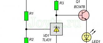
Voltage indicator on two-color LED
Another popular indication scheme is one that uses a two-color LED to display the state of charge of the battery or to signal when a lamp is turned on or off in another room. This can be very convenient, for example, if the light switch in the basement is located before the stairs leading down (by the way, do not forget to read an interesting article on how to illuminate the stairs with LED strip).
Before you go down there, you turn on the light and the indicator lights up red, when off you see a green glow on the key. In this case, you don’t have to go into a dark room and feel for the switch there. When you leave the basement, you know by the color of the LED whether the light in the basement is on or not. At the same time, you monitor the health of the light bulb, because if it burns out, the red LED will not glow. Here is a diagram of a voltage indicator on a two-color LED.
In conclusion, we can say that these are only the basic possible schemes for using LEDs to indicate voltage. All of them are simple, and even an amateur can do them. They didn't use any expensive integrated circuits or anything like that. We recommend that all amateur and professional electricians acquire such a device so that they never endanger their health by starting repair work without checking the presence of voltage.
Which resistor should I use?
To select the optimal resistor resistance, you need to use Ohm's law.
Suppose we took a red LED for the indicator with a nominal current value of 18 mA and a forward voltage of 2.0 Volts.
Let's explain where the number 311 comes from. This is the peak of a sine wave along which the voltage in our network changes. Without going into the realm of mathematics with all its calculations, we can simply say that the peak voltage is 220 * √2.
Sometimes there are circuits that do not have a rectifying diode. In this case, the resistance must be increased several times in order to reduce the current and protect the indicator light from burning out.
Expert opinion
It-Technology, Electrical power and electronics specialist
Ask questions to the “Specialist for modernization of energy generation systems”
REVIEW OF ELECTRIC TESTS It can be recommended for full power supply of a powerful LED or a line of lighting LEDs, as well as if galvanic isolation from a high voltage network is required. Ask, I'm in touch!
Option for car
A simple circuit for indicating the vehicle's on-board voltage and battery charge. The zener diode limits the battery current to 5V to power the logic chip.
Variable resistors allow you to set the voltage level to trigger the LEDs. It is better to carry out the setup from a network stabilized power source.
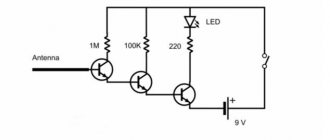
Life-threatening voltage detector, manufacturing
The device is made with three transistors, without a board for surface mounting.
Please note that the circuit uses transistors of different structures. There are no special requirements for them; almost any will do. An LED and a buzzer are used as signaling elements. The role of the antenna is played by a piece of wire 5 cm long.
The detector is powered by two little finger elements.
The body is a transparent plastic tube.
After assembly, if all elements of the circuit are in working order, the detector starts working immediately and does not need adjustment.
Diagram for connecting an LED to a voltage of 220 volts (quenching capacitor + resistor)
Everything is the same here, except that a resistor was added to the chain. In general, the influence of a resistor can make the entire circuit more predictable and more reliable. There will be less high voltage pulse currents here. This is good!
(...as in the diagram above, a quenching capacitor + resistor is used)
All the pros and cons are similar to the option with a quenching capacitor, but there is no reliability here either. Moreover, the use of a diode rather than a zener diode will affect the protection of the LED when the capacitor is discharged. That is, all the current will flow through the LED, and not, as in the previous case, through the LED and Zener diode. This option is so-so. And here is the last case, using a resistor.
Nuances in the operation of the voltage indicator
A self-assembled LED indicator, just like industrial devices of this type, can be used to check the presence of voltage. It is not a measuring device, but only indicates the presence or absence of voltage. Having gained some experience with the pointer, you can determine the voltage between two conductors by the brightness of the light-emitting diode. However, for accurate measurements you need to use pointer or digital voltmeters.
Unlike indicators with gas-discharge lamps, the LED indicator cannot be used to find the “phase” by touching one of the probes with your finger. The device has low internal resistance, and this method of searching for a phase conductor can result in electric shock.
The principle of reducing the supply voltage for an LED
Two power paths can be selected to supply low voltage loads. The first is, so to speak, the classic version, when the power is reduced by a resistor. The second option, which is often used for chargers, is a quenching capacitor. In this case, the voltage and current flow as if in pulses, and these same pulses must be precisely selected so that the LED and the load do not burn out. This requires a more detailed calculation than with a resistor. The third option is a combined power supply, when both methods of reducing voltage are used. Well, now about all these options in order.