When carrying out electrical installation work, it may be necessary to test the cable, for example, when marking cores and wires, checking the insulation and integrity of the wiring, as well as searching for a broken electrical cable. Let's consider the ways in which testing can be carried out, as well as the equipment necessary for this purpose.
Testing methods depend on the purpose for which it is performed. To check the integrity of the cable for a break or electrical connection between its wires (short circuit), the continuity test can be done with a tester based on a battery and a light bulb, or you can use a multimeter for this purpose. The latter is preferable.
Despite the fact that the price of a multimeter is higher than a primitive device, we recommend buying it; this device will always be useful in the household.
To check the cable, the multimeter must be turned on in the appropriate mode (diode or buzzer image).
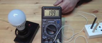
When checking a wire for a break, the tester is connected to its ends as shown in the figure. If the cable is intact, the light will glow (when testing with a multimeter, a characteristic sound signal will be heard).
Checking for a break
If the cable has already been laid, then on one side it is necessary to connect the wires together and ring the wires at the other end;
when checking the presence of an electrical connection between the cable cores, the tester probes are connected to different wires. Unlike the previous example, there is no need to twist the wires on the other side. If there is no short circuit between the wires, the light will not light (when testing with a multimeter, no beep will sound).
Expert opinion
It-Technology, Electrical power and electronics specialist
Ask questions to the “Specialist for modernization of energy generation systems”
Checking a wire break in a circuit with a multimeter | 2 Circuits If everything is fine, the measurement result will be close to 0 Ohm, if something goes wrong, the measurement will be several kΩ, MΩ, or even the display will simply show a 0L open circuit. Ask, I'm in touch!
How to check voltage and find phase in home wiring | DIY apartment design and renovation
- set the maximum range on the device - 2000 kOhm;
- connect the probes to the wires and see what the device display shows. Considering that the wires have a certain capacitance until it is charged, the readings may vary. After a few seconds, the device display can display the following values:
- one, this indicates that the insulation between the wires is normal;
- zero – there is a short circuit between the cores;
- some average readings, this can be caused either by a “leak” in the insulation or by electromagnetic interference. To determine the cause, switch the device to the maximum range of 200 kOhm. If the insulation is faulty, the display will display stable readings; if they change, then we can confidently talk about electromagnetic interference.
We test cables and wires in different ways
When checking the integrity of cable products, an electric current is passed through one of the wires, and an ohmmeter, light bulb or sound device is included in this circuit, which rings when testing the wire, therefore these tests are called continuity testing.
The purpose of the test can be twofold - to check the serviceability of the wire, or to find the two ends of one core. The circuits are tested using a multimeter or special devices.
Even the simplest and cheapest multimeter copes with these tasks perfectly, because in this case the measurement error does not play any role - the current either flows or not, one of two things. Therefore, an electrician should always have at least a simple multimeter in his arsenal; in addition to checking the integrity of cables, it can measure voltage, insulation resistance and current.
But for a single check, you can build a dialing device from improvised means. First you need to consider ways to check cables.
Checking the integrity of the insulation
This test is carried out at one end of the cable only. To do this, strip the conductors, turn the multimeter into resistance measurement mode, and select the megohm range.
Without touching the probes with your fingers, check with them whether there is a breakdown between the wires.
Due to the capacitance of the cable wires, the readings on the electronic display will initially change, but within a few seconds the capacitance will charge and the indicator should show one on the left side of the screen - this means that the resistance is so high that it is outside the measurement range.
If zero is established, this means that there is a short circuit between the wires. It happens that the multimeter shows some average value. If the cable is new, then it is of poor quality, and the moistened insulation leaks, or it may be affected by electromagnetic interference.
In this case, the device is switched to a lower range - hundreds of kilo-ohms, and the readings are monitored - in the case of electromagnetic interference, the value displayed on the display will constantly change, but if it is faulty insulation, the readings will be stable.
Basic units of measurement
Be sure to watch your hands when checking - they should not touch the probes, so as not to create errors in measurements. Often in this way you can check the serviceability of wiring located in a damp wall by connecting to wires that are known to be de-energized and not connected to electrical appliances.
Conductor continuity test
In a working cable, each core should conduct electric current, and there should be no short circuit between them.
If the cable has marked wires, then there is no need to identify the pairs of ends of each core. In this case, there is no need to pull the ends of the cable into one place, or pull the wire from the multimeter to the other end.
After checking the insulation for breakdown according to the method described above, it will be enough to strip and connect the wires at one end of the cable into one twist, and make a continuity test at the other.
The multimeter is switched to the resistance measurement mode, the lowest range is set - as a rule, it is 200 Ohms, or a special speaker icon specifically designed for dialing.
Multimeter in speaker switch position for dialing
Always check the multimeter itself before testing - to do this, connect two probes together - the tester should ring and show zero, after which you can take measurements.
To check, it will be enough to connect one probe to any wire, and the other one to go through all the wires one by one - they should ring everywhere, that is, the device should emit a sound signal if it has this option, or show a resistance close to zero.
Some long cables may have a resistance of several ohms - this is normal. If the device shows one on the right, it means there is a break somewhere in the tested wire.
How to test wiring between junction boxes
Very often it is necessary to find the ends of one conductor in a tangle of single-color wires in junction boxes. In this case, you cannot do without an additional conductor, with a length greater than the distance between the two boxes.
First, the additional wire itself is called, then one end of it is connected arbitrarily to one terminal in the junction box, and one of the multimeter probes is connected to the other end of the additional conductor. Electrical wiring must be de-energized, all sockets must be free, and switches must be turned off.
With the remaining probe, they check the conclusions in another box - the one on which the tester will ring or show zero and will be a single wire. Its ends are marked, and the ends of the remaining wires are identified in the same way. It is better to equip the additional wire and the probes themselves with alligator clips, in this way hooking them onto the core being tested, which will allow you to carry out continuity testing of the wiring yourself.
alligator clip
If one of the wires is broken, then it is found by the method of exclusion by identifying and checking the remaining wires. In the same way, you can carry out dialing and checking the car wiring, having first disconnected the battery.
Alternative dialing methods
If the tester is missing, it can be replaced using a battery or batteries and a light bulb. The test conductor is connected to the break in this circuit; the procedure is no fundamentally different - if the wire is working properly, the light bulb should light up.
Testing multi-core cables for the purpose of marking them
When marking multi-core cables, you can use the methods described above, but there are ways to significantly simplify this process.
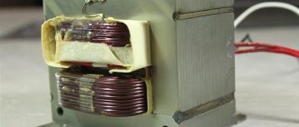
Method 1 : use of special transformers that have several secondary winding taps. The connection diagram for such a device is shown in the figure.
As can be seen from the figure, the primary winding of such a transformer is connected to the power supply network, one end of the secondary winding is connected to the protective shield of the cable, and the remaining terminals are connected to its conductors. To mark the wires, it is necessary to measure the voltage between the screen and each wire.
Method 2 : Use a block of resistors with different values connected to the cable wires on one side, as shown in the figure.
To identify the cable, it is enough to measure the resistance between it and the screen. If you want to make such a device with your own hands, then you should select resistors in increments of at least 1 kOhm to reduce the influence of wire resistance. Also, do not forget that the value of the resistors has a certain error, so first measure them with an ohmmeter.
When checking a multi-core telephone cable, installers often use a dialing headset, for example TMG 1. Actually, these are two telephone handsets, one of which is connected to a 4.5 V battery. Such a simple device allows you not only to check the cable, but also to coordinate your actions during installation and testing.
Searching for a phase wire on a potato cut
With this method of searching for a phase conductor, you need to take a fresh medium-sized potato tuber and cut it in half. Place conductors at a distance of 3-5 cm on the cut of half the tuber. Connect one conductor to a heating pipe (in an apartment building) or to a ground loop outlet (in a private house). Using a second conductor through a resistance (for example, a resistor) of 1 MΩ (power from 0.5 watts), search for phase. After 5-10 minutes, a green spot will appear on the potato cut near the phase wire.
Source
Safety rules when making calls
Any electrical work, including diagnostics of conductors, requires compliance with all precautions and electrical safety rules. The main rules, the observance of which will save your life and health, are as follows:
- Always operate with power off. Post a sign that says “DO NOT TURN ON. PEOPLE WORK!” at a switch or machine;
- Do not touch exposed conductors with bare hands, use special clothing and special tools;
- Use power tools with sharp edges carefully: use gloves and do not damage the cord;
- At the end of the work, all faulty systems must be de-energized, and exposed wires must be properly insulated.
Take care of yourself and remember, if you doubt that you are capable of working with electrical networks, entrust this task to professionals.
Checking different types of electric motors using a multimeter
How to use a multimeter - measuring voltage, current and resistance
How to test a capacitor for functionality with a multimeter?
How to install an electric doorbell - step-by-step instructions
What kind of lighting do you prefer?
Built-in Chandelier
Determination of the cross-sectional area of a conductor by its diameter
Why does the plug, RCD or automatic circuit breaker knock out when turning on or during operation of the washing machine?
How to test wires with a multimeter: how to check a wire for a break or continuity, checking the circuit with a tester, cable continuity
These pointers also work based on the fact of current passing through them. Their tips are placed between the tested phase and zero potentials. The person does not come into contact with the controlled current and is separated from it by a layer of reinforced insulation.
Expert opinion
It-Technology, Electrical power and electronics specialist
Ask questions to the “Specialist for modernization of energy generation systems”
How to test the wiring in a car with a multimeter: device, procedure for diagnosing a cable Inside any physical body there is a certain number of different electrical charges of electrons, anions, cations, holes. Ask, I'm in touch!
Types of voltage indicators for home network
A common mistake made by inexperienced users that creates a traumatic situation is the use of electrical appliances for purposes other than their intended purpose.
All electrical devices, including indicators, are designed to operate only under a certain type of voltage.
This value is always indicated by the manufacturer on the housing.
You cannot use a 220 volt indicator on a 380 or higher network. This is life-threatening.
Voltage indicators up to 0.4 kV can be triggered based on the passage of current through them from:
In the first case, the current flows through the operator’s body, and in the second, bypassing it along the pointer conductors connected to the circuit.
Capacitive voltage indicators
They are made in the form of a screwdriver with a slip ring. The pointer tip is applied to the metal of the wire being tested or the contact of the switching device, and a special metal pad is touched with a finger.
In this case, an electrical circuit of alternating current is created, limited by a resistor built into the pointer, along the path:
Naturally, the pointer current is limited to a safe value of fractions of a milliamp. When it appears, the light from the neon light bulb mounted in the housing lights up.
Professional capacitive-type voltage indicators are less susceptible to this phenomenon, but still are not completely free from it, although they can perform a number of additional functions.
When working with such indicators, you can also make a mistake for the reason that in the bright light of the sun, the visual perception of the glowing indicator light bulb is weakened, and you simply may not see it light up. This is especially true for LED budget models.
Under such conditions, self-powered indicators work better, additionally signaling the appearance of voltage by squeaking a buzzer.
Bipolar voltage indicators
These pointers also work based on the fact of current passing through them. Their tips are placed between the tested phase and zero potentials. The person does not come into contact with the controlled current and is separated from it by a layer of reinforced insulation.
Such indicators have a signal lamp and two resistors in their housing:
Of the older models, MIN-1 is still popular. UNN-10. The operating voltage range is between 70÷660 volts, and the indicator lamp lights up from 60÷65. These devices can operate in both AC and DC circuits.
Expert opinion
It-Technology, Electrical power and electronics specialist
Ask questions to the “Specialist for modernization of energy generation systems”
How to check the power on the wire The cause of battery death, voltage surges, and unnecessary values on the instrument panel can be various sensors in the car. Ask, I'm in touch!
How to Measure Battery or Battery Voltage
All kinds of batteries and various accumulators, in general, everything where you see “+” and “-” are all sources of direct electric current. Measuring DC voltage is no more difficult than alternating voltage.
To do this, take, for example, the most ordinary AA battery. Connect the red wire of the multimeter to “+” terminal of the battery, and the black wire to the “-” terminal of the battery . If you connect them the other way around, nothing bad will happen, the readings will simply be displayed on the multimeter screen with a minus sign, something like this.
Usually the voltage on the batteries is low, so you don’t have to be afraid to press the probes with your fingers. Up to 20 volts you most likely won't feel anything. In the case of an AAA battery, its maximum voltage is 1.5 volts, which is not at all dangerous for a person.
As we can see from the multimeter readings, the voltage in our battery is 1.351 volts, which means the battery is still fully charged and can be used.
In a similar way, you can check any other batteries and measure their voltage, and as you now know, there is nothing complicated about it.
Voltage measuring instruments
Indicators or pointers by their action indicate the presence of a certain voltage level in the area being tested. They are not intended to determine its magnitude.
The measurement function is assigned to instruments that are endowed with certain metrological characteristics - voltmeters.
For digital instruments, the functions of the measuring head are assigned to measuring, logical and information organs.
To perform such work, it is recommended that a home craftsman purchase a combined device that has the functions of measuring voltage, current, and resistance.
Of the older models produced in the USSR, the Ts4324 tester works well. Half-worn from long-term use, the quality mark applied to the case still lives up to its purpose.
Of course, such pointer instruments in modern times are considered an anachronism. They require attention, knowledge, the ability to make switches and do quick mental math. And errors in the position of the toggle switches during measurements result in burnout of the internal elements of the circuit.
Previously, we had to rescue comrades who had burned their devices through carelessness and help them with repairs.
Since then, the schemes of Soviet testers have remained. If anyone needs them, write in the comments, I’ll send you photos of the required pages by email.
Modern meters of electrical parameters are called avometers, ampere-voltmeters or multimeters.
Their essence is the same: based on an electronic or microprocessor circuit, precise measurements are performed, sometimes almost automatically, with instantaneous display of information in text form on the display.
However, the switches and buttons remain, they must be used intelligently.
Checking one long wire
What if you only need to check one core? It can be done like this. For example, there is a 2-wire cable, and I wonder if only one line is broken, and if so, which one.
Basically you should do the same as in the previous step, only using an additional wire with any cross-section.
We take an additional cord and screw it on one side to the wire that we want to examine. We lead him to the second place where the second end of the wire is located.
We touch with probes and measure. If everything is good, the measurement result will be close to 0 Ohm, if something goes wrong, the measurement will be several kΩ, MΩ, or even the display will simply show 0L - an open circuit.
Conductor integrity check
Before starting work, it is important to correctly position the probes: black - COM, red - up to 200mA in VΩmA, above 200mA in 10ADC.
Expert opinion
It-Technology, Electrical power and electronics specialist
Ask questions to the “Specialist for modernization of energy generation systems”
The principle of operation of voltage indicators If the insulation is faulty, the display will display stable readings; if they change, then we can confidently talk about electromagnetic interference. Ask, I'm in touch!
Setting up a multimeter before dialing
Before starting measurements, the switch on the multimeter must be set to dialing mode (->Ι- and buzzer icon).
The ends of the test leads with probes must be installed in the appropriate sockets. The black wire goes to the COM socket, and the red wire goes to the VΩmA socket. This combination will allow you to maintain polarity when taking measurements, but in the case of checking the integrity of the wires, continuity will not play any role.
Next, to make sure that the multimeter is working properly, the black and red probes must be connected to each other. In this case, a signal should sound (if there is a buzzer), and a value close to or equal to zero will appear on the screen.
Conclusions and recommendations
- We always carry out resistance measurements in the free state of the tested conductors. Measuring a live wire is lethal. At least for a multimeter.
- Measuring a circuit is actually testing its electrical resistance.
- When the conductor is not damaged, the measurement result should be no more than a few ohms.
- Before performing the break measurement itself, it is worth performing a test measurement on the probes to check whether the device is working.
Checking for broken wiring in a car is done in a similar way, with the only difference being that you don’t have to worry about a 220 V current shock due to the absence of one (this does not apply to electric cars - there are even 600 V there!).
An indicator screwdriver is a useful tool for electrical installation work.
Safety is the main condition for carrying out any work on electrical wiring in the house. Therefore, it is very important to make sure that there is no voltage in the wire. One very important tool called an indicator screwdriver will help you do this. How to use it correctly?
In the house, power is supplied to the electrical wiring from a common switch
Current flows (at a voltage of 220 V) through the phase wire to the consumer, then it returns through the neutral wire to the general switch. Moreover, the neutral wire is energized only when the current-consuming device is operating. So, an indicator screwdriver helps to check whether there is voltage in the wire or not, that is, whether it is “phase” or not.
Before starting any work related to electricity, it is recommended that you become thoroughly familiar with some general rules for working with electrical wiring and learn how to identify the absence or presence of voltage in electrical wires in order to avoid dangerous situations.
Electricity
The very first step when working with electricity is to identify which wire has a phase, that is, determining which wire is live and the other is neutral. After finding the phase wire, try not to touch it so as not to get an electric shock.
How to determine the phase
Phase detector: operating principle
Application of a phase detector
In what cases is it necessary to determine whether there is a phase in a given wire?
Troubleshooting
What dangerous mistake should you avoid?
Expert opinion
It-Technology, Electrical power and electronics specialist
Ask questions to the “Specialist for modernization of energy generation systems”
How to test wiring This sound alarm is convenient for testing in hard-to-reach places where it is not possible to observe the multimeter display. Ask, I'm in touch!
Using a control lamp
This method consists of touching one contact of the wire from the control lamp to the conductor, and the other end to the ground (for example, to heating radiators or other water pipes stripped to metal, or a special ground provided by the developer), if there is a phase in the conductor , the incandescent lamp lights up. If the lamp does not light up, then it is not a phase wire.
Please note that pipes are not always reliable grounding. Therefore, for accurate measurements, a conductor that is definitely well grounded is desirable. And also a known neutral wire is suitable instead.
Before searching for a phase conductor using a test lamp, you need to make sure it is working. To do this, the contact wires from the lamp are connected to a known working power source. If the incandescent lamp is working properly, the wires in the socket are connected securely and have no mechanical damage, then it will light up.
It is easy to make a test lamp yourself by connecting a two-core stranded copper insulated conductor to the contacts of an electric socket into which an incandescent lamp with a voltage of 220 volts and a power of up to 100 watts is screwed.
With this method of searching for a phase wire, there is a risk of electrical injury if the work is performed in an apartment building. The heating circuit of such houses is located in common areas (heating risers). If an electrical potential appears on metal parts and at the same time touches the heating pipes, a person may receive an electric shock.
Please note that when checking, you should not pick up the exposed phase conductor. This will result in an imminent electric shock, which, being limited by the resistance of the body and the incandescent lamp, will lead to injury.
When implementing this method of searching for a phase wire in a private house, the risk of electric shock is much less. If there is a grounding loop at home, you can use a tap (outlet) of the wire from the grounding loop to the search location. And also, as in the case of the apartment described above, instead of grounding, a known zero will do.
To ensure the necessary safety when performing work using a pilot lamp, you must use a tool with insulating handles. Measures for connecting the wire to the ground loop or heating pipes should be carried out using dielectric gloves.
Remember that the use of warning lamps is prohibited by paragraph B2.3.24. Safety rules for the operation of consumer electrical installations (PTBEEP),
Checking devices
Checking the tachometer
To test a new tachometer, you need to connect the multimeter to the terminal on the back of the device and ground. When current is applied to the device, the multimeter will record readings. This technique can be used for any device.
Many devices operate on current that passes through a voltage stabilizer. If several instruments display incorrect readings at once, the stabilizer may be faulty. To check, you need to connect a multimeter to the output connector and turn on the ignition.
Stabilizer check
In modern cars, some devices are powered by a voltage stabilizer. If the stabilizer breaks, the instrument readings are distorted. Before checking each device, you need to check the stabilizer itself by connecting a multimeter to its output connector and ground.
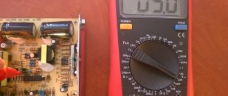
The multimeter should show approximately 10V, small deviations are due to the action of the rheostat. A strong deviation indicates that the multimeter needs to be replaced.
We check the wiring in the apartment with a multimeter
Let's take as an example a modern apartment in which the wiring is done in accordance with current requirements and standards. This means that when laying the lighting lines and power outlets, they were separated, and separate wires were laid for them in each of the rooms. Each of these circuits is powered from the apartment panel through a separate circuit breaker.
If the light has gone out in one of the rooms, you should first check that the lamp is working properly. Before starting work, it is necessary to turn off the power to the room/apartment depending on the power supply. When using an opaque incandescent lamp in a lamp, the integrity of the filament is difficult to visually determine, so you will need a multimeter and its continuity function. Let's figure out step by step how to do this correctly.
First you need to check the shield for triggered circuit breakers. In the first case, they will be in the on position (then the fault may be hidden in the room switch, lamp or socket). The likelihood of damage to the wiring in such a situation is low. If the device works, you will need to check everything except the room switch, including the switchboard itself.
If the machines don't work
- Make sure there is voltage at the input and output of the machine. If it is, you can proceed to further verification.
- Prepare the device for operation and check its serviceability by short-circuiting the measuring leads.
- Unscrew the lamp from the socket.
- Touch one of the measuring probes to the base (the metal part of the lamp with threads), and the second to the central contact of the lamp (the insulated center of the end part of the base).
- A sound signal and instrument readings that are different from 0 or 1 mean that the lamp is working. If it is faulty, you need to replace it, which will solve the problem.
- We check the cartridge for serviceability. To do this, you need to disassemble the lamp, make sure that the connected wires and contacts are intact. If everything is in order, then the cause of the failure is not in the cartridge. If malfunctions are detected, they must be eliminated. The lamp cannot be screwed in yet.
- We check the serviceability of the room switch. To do this, remove the plastic cover, unscrew the screws and take it out of the mounting box. We inspect the equipment for the appearance of carbon deposits and check the tightness of the fasteners. If everything is in order, you need to install the measuring ends of the tester on the contacts of the switch. The appearance of a sound signal when dialing in the on position will indicate that the equipment is working properly. The wires do not need to be disconnected.
During such a check, as a rule, a malfunction is identified, which becomes the cause of all the troubles. Eliminating it allows you to quickly solve the problem.
If the machine worked
To ensure electrical safety during work, in this case the voltage is turned off using a general apartment circuit breaker. Next, the serviceability of the socket and the wires connected to the lamp is determined according to the algorithm described above. If there are no faults, you need to check the wiring itself using a multimeter and the continuity function. Such malfunctions happen quite rarely, but they still happen, for example, when installing suspended ceilings or decorative interior elements.
The wiring in this case is performed as follows.
- Using a screwdriver, disconnect the connected conductor (if installed correctly, it is located at the bottom) and move it to the side. The “zero” of this group is, as a rule, located at the zero clamp under the machines.
- Unscrew the incandescent lamp from the socket. Using a ready-to-use tester, we check the line by connecting one of the measuring probes to “zero” and the other to the disconnected conductor. If the device beeps, it means the wiring is shorted.
- In this case, in the room under the ceiling above the switch, we find and open the junction box. We disconnect the wires.
- We check all groups of wires for short circuits. To determine the section of the circuit in which there is a short circuit, we again check the circuits on the apartment panel with a multimeter. If the signal sounds, it means that it is the wire laid from the switchboard to the box in the room that needs to be repaired. Otherwise, the search will need to be continued until a result is obtained.
Checking the electrical wiring
Check at the installation stage
First, let's look at the potential problems that an electrician can expect when installing new wiring. As a rule, such wiring is laid along bare walls (or in specially made grooves), and then covered with plaster and finishing.
The first check of all electrical wiring must be carried out before starting any plastering work!
Otherwise, an unpleasant surprise may await you in the future: to troubleshoot problems with the wires, you will have to open the plaster.
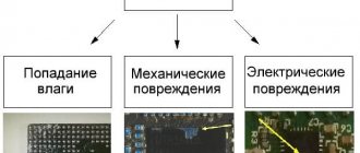
At this stage, possible sources of problems with electrical wiring can be divided into two groups:
And if the first group can be dealt with only by vigilant supervision, then electrician errors can be avoided by carefully following the drawn wiring diagram when laying it and carefully checking it before starting finishing work.
Easy testing of new electrical wiring
So, we have come to the point where the wiring is laid. And it seems to be laid out correctly.
What can we do at this stage to make sure the wiring is working properly?
- We check the wiring for a short circuit: there should be no contact between zero, phase and ground . The quality of wire insulation at high voltage directly depends on the quality of the cable, so if you didn’t skimp and didn’t buy the cheapest option, then, as a rule, there are no problems here
Expert opinion
It-Technology, Electrical power and electronics specialist
Ask questions to the “Specialist for modernization of energy generation systems”
Checking one long wire It is based on the connection between the phase wire in the network and the ground of a working incandescent lamp, which glows under load and does not burn without it. Ask, I'm in touch!
Exposed wire: safety precautions when working with it
Don't touch the damaged wire
We all know that if you touch a bare live wire, it is fraught with the most dire consequences, even several hours after the incident. Therefore, you should be wary of such wires. But what to do if it is in your apartment or house?
After all, bypassing it is not an option, and this malfunction needs to be fixed. This is exactly what we will talk about in our article.
Options for dealing with damaged wiring and solutions
There may be several options for your encounter with exposed wires:
- First , you may find exposed wires in your home or apartment in a place you've never looked at.
- Secondly , wires without insulation can be formed as a result of a short circuit in the wiring. Well, in the latter, you can damage the wire yourself during construction work or through negligence.
Unknown damaged wire
This option is most often found when buying a house or apartment. When, during a more thorough examination, you discover such unpleasant moments. But don’t panic, if you follow our instructions, we will solve this problem in just a few minutes.
Unknown damaged wire
So:
- First of all, if you find exposed wires, do not turn on the lights or turn on any electrical appliances. This may result in voltage being applied to the damaged area and causing a short circuit.
- Take a voltage tester and check that there is no voltage on the damaged wiring. If voltage is present, this means that the wiring is not damaged, but that the insulation has crumbled due to aging or overheating.
- If there is no voltage, this does not mean that the wiring is damaged. Maybe there's just a switch somewhere that's turned off. In any case, we relieve the tension from this area by turning off the corresponding group machines, and if it is impossible to accurately determine the group’s membership, then the input machine at home.
Note! In any case, after a long period of non-use of the voltage indicator, it should be checked. This is done by touching live parts that are known to be energized. Only after such a check can you be sure of the reliability of its work.
- After removing the tension, we once again make sure that it is absent in the damaged area. Only after this, using electrical tape or heat shrink, we insulate the wires. Moreover, we do this in such a way as to eliminate the possibility of water getting under the insulation in the event of flooding of the room.
- If we had voltage on the wires, then we isolate them without changing their location or connecting them to each other. We do the same if there is no voltage, but there are no obvious signs of a short circuit in the exposed area.
- If there is no voltage and obvious traces of a short circuit are visible on the bare area, then we insulate each wire separately. Our instructions for troubleshooting wiring faults will help you further investigate this area.
- After applying high-quality insulation, voltage can be supplied. At the same time, make sure that there are no sparks, extraneous noise or other sound or light effects at the damage site that indicate damage.
Damage to the wire after a short circuit
A short circuit in the wiring (see Finding and fixing a short circuit in the electrical wiring with your own hands) can occur due to flooding, heating, improper installation, aging insulation and many other factors. Clear signs of this phenomenon can be considered sparking in the wiring and shutdown of the group circuit breaker in this area. As a result, wires without insulation may form, which urgently need to be insulated.
Damage to the distribution box due to a short circuit
So:
- If you witness a short circuit in your apartment or house, do not rush to inspect the damage site. First of all, make sure that there is no voltage at this electrical point. If the shutdown does not occur, automatically perform it manually using a group or input machine.
Note! Never attempt to break a short circuit with light switches, packet switches, or circuit breakers. This can lead to damage at best, and in the most severe cases, to hand burns.
- After removing the voltage and checking its absence with an indicator, you can begin inspection. Several options are possible. In the first case, the location of the damage can be clearly visible and fixing it with your own hands will not be difficult. In the second case, the location of the short circuit may be a bunch of wires, among which it is almost impossible to determine the most damaged one.
Note! If the point of damage is the junction box, then remove the voltage from all wires and cables laid in it.
But the photo shows the consequences of a short circuit
- Our further actions depend on the availability of wire stock. If there is one, then it is better to bite out the fused wiring harness and carry out further repairs with undamaged wires. If there is no reserve, then we separate each wire and insulate it separately. The choice of option largely depends on the brand of wires.
- After each wire is insulated separately from the others and there is no contact between them, you can try applying voltage to determine the extent of damage. In this case, you need to be extremely careful, because the damage may not be in the place where the wires fused.
- We carry out further repair work based on the nature of the damage and in accordance with our recommendations for eliminating it. You will also find instructions for carrying out such work on our website.
An indicator screwdriver is a useful tool for electrical installation work.
- set the maximum range on the device - 2000 kOhm;
- connect the probes to the wires and see what the device display shows. Considering that the wires have a certain capacitance until it is charged, the readings may vary. After a few seconds, the device display can display the following values:
- one, this indicates that the insulation between the wires is normal;
- zero – there is a short circuit between the cores;
- some average readings, this can be caused either by a “leak” in the insulation or by electromagnetic interference. To determine the cause, switch the device to the maximum range of 200 kOhm. If the insulation is faulty, the display will display stable readings; if they change, then we can confidently talk about electromagnetic interference.
How to connect wires
Before measurements, it is important to strip the ends of the wires from insulation and remove oxide from the cable cores. The oxide on the wires may have high resistance, which will be higher than the limit of the selected resistance mode of the device, which will give incorrect readings.
Before making the call, you need to remove the mains voltage from the electrical wiring and remove the terminals from the battery in the car. If there are capacitors in the wire continuity circuit, then they need to be discharged by short-circuiting the terminals. All these precautions will help avoid damage to the multimeter and give more reliable results.
For convenience, when making calls, use special wire clips - “crocodiles”. The “crocodile” is put on the probe and clamped onto a section of the wire. The use of such clamps increases the convenience of working with wires, as your hands are freed.
Safe and correct operation of the multimeter
Working with electrical devices and networks must be safe. This rule also applies to the procedure for ringing conductors with a multimeter. Let us highlight the main recommendations that must be followed before and during work:
- First of all, the circuit must be completely de-energized by turning off the machine in the switchboard and removing the batteries (if the object in question is an electronic device).
- The capacitors in the circuit must be discharged by short-circuiting. Otherwise, during measuring work, the multimeter may fail.
- For convenience when making measurements, it is recommended to use special tips (“crocodiles”) at the ends of the measuring wires. These devices create reliable contact with the conductor being tested and, at the same time, free your hands.
- When trying to fix the probe, it is not recommended to touch the bare wires and the tip of the probe with your fingers. Otherwise, the results obtained may be incorrect.
How to identify problems
Troubleshooting is simplified if you have an initial wiring diagram. The plan is attached to the technical passport of the housing. If not, a drawing is drawn up - if the rules are followed, the routes run in a straight line (vertical, horizontal).
Regular testing with a multimeter will help identify problems. It is not difficult to determine in which area the breakdown occurs. For example, if the sockets and switches connected to the box do not work, the problem is here. If there is only one, there is a breakdown between the box and the socket.
Modern technologies and systematic checks will ensure safety during operation of electrical wiring in the apartment and increase service life. The main thing is to follow the principles and rules of work.
Expert opinion
It-Technology, Electrical power and electronics specialist
Ask questions to the “Specialist for modernization of energy generation systems”
Detection of breakdowns We touch one end of the wire with one tip, and the other end of the wire with another and wait for a sound signal or the measurement result on the display. Ask, I'm in touch!
How to choose a sample in a store
When purchasing a sample in a store, make sure it is functional. Please insist on asking the seller to check it. In response, he will most likely send you to the nearest outlet and tell you to check. Tell him that you are afraid of electricity, that you need a tester that works accurately, and most importantly, that he shows you how to check it.
After some bickering, keep an eye on the seller. He will approach the outlet, take the probe in his hand, press his thumb against the end of the probe, and point the metal part of it directly into one of the holes in the electrical outlet.
If the light does not light up, point the probe into the second hole. The light should light up. He will demonstrate this to you. And you will see for yourself that since he did it, then you can do the same at home.
What dangerous mistake should you avoid?
- Check the voltage on the machine.
- The device is tested for serviceability - the ends of the wires are short-circuited.
- Remove the lamp from the socket.
- One probe touches the base, the other touches the center.
- If a signal appears and a value on the screen other than 0 or 1, the device is working properly.
- They check the cartridge - disassemble the device, check the integrity of the contacts and wires.
- They check the switches - remove the protective cover, unscrew the bolts, and pull them out of the wall; carry out an inspection; The ends of the multimeter are connected to the contacts - if there is a sound and a value, the device is working properly.
Useful tips Connection diagrams Principles of operation of devices Main concepts Meters from Energomer Precautions Incandescent lamps Video instructions for the master Testing with a multimeter