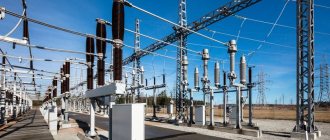
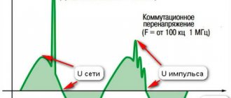
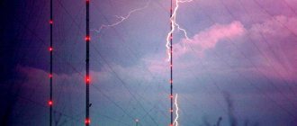
An overhead power line (OHL) with a voltage of up to 1000 V is the most common and most vulnerable element of the energy distribution system, especially in rural areas, as well as among small towns and suburban areas of megalopolises. If you carefully study the statistics of accidents in power systems, you will notice the fact that the cause of 75-80% of emergency power line outages in spring and summer are thunderstorms.
Figure 1. Power lines (PTL)
Basic concepts and definitions
Based on the “Rules for the Construction of Electrical Installations” (PUE, edition 6), the term “overhead line” refers to an overhead line made using bare wires. Based on what is written in the PUE (edition 7), power lines can be made using both insulated (VLI) and non-insulated wires.
In the seventh edition of the PUE, the term “VLI” is explained in this way - these are lines using self-supporting insulated wires (SIP). Let's consider how to organize lightning protection of overhead lines in practice. In this case, it is necessary to answer a fairly simple question: what exactly is the object of external protection of overhead lines from lightning?
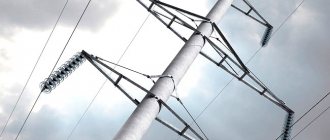
Figure 2. Lightning discharges over power lines
Ultimately, the object of external lightning protection of overhead lines made with bare wires is the electrical installations of the electricity consumer. Bare wires are not subject to protection at all; on overhead lines up to 1000 V, means of protecting wires from direct lightning strikes are usually not used. To significantly reduce the statistics of short circuits that occur between wires, VLI and SIP are used.
When using insulated wires when constructing power lines, the risks associated with short circuits due to overlapping and electrical contact of wires with trees are completely eliminated; the risk of ground faults due to falling wires is reduced. The use of VLI significantly reduces the contour area for the overvoltage induced by an electromagnetic lightning pulse, which brings the safety of such lines closer to the safety of an underground cable. It is also necessary to note electrical safety when carrying out work on the line, since the likelihood of electric shock is significantly reduced. In addition, the use of insulated wires significantly reduces the impact of discharges and reduces the likelihood of arc faults.
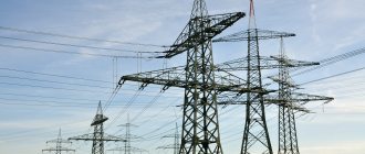
What processes occur in power lines with bare wires if they are hit by a direct lightning strike? First, you can see phase-to-ground discharges that occur between the wire itself and the support traverse, then, under the influence of the electromagnetic forces of the arc itself, these discharges move along the lines themselves. Burnout of bare wires does not occur due to the displacement of the ends of the arc along the lines.
Figure 3. Processes on power lines with bare wires caused by a direct lightning strike
When such a physical phenomenon as a short circuit on an overhead line occurs, the processes accompanying it occur according to a completely different algorithm: the ignition of an arc is observed only between each individual conductor and the structure holding the wires on the support. The insulation layer is a natural obstacle to the freely moving arc, and the arc therefore burns only at a specific point, as a result of which the wire is burned out.
Figure 4. Short circuit to VLI
Short circuits on the overhead line trigger the automation and lead to the line being disconnected. There are other threats - these are overvoltage spreading along the line. To protect against them, surge suppressors (SPDs) and surge protection devices (SPDs) are used.
Lightning protection of power lines
Objectives and criteria for lightning protection of lines
As already noted, the overhead line annually experiences several dozen direct lightning strikes for every 100 km of length. The main danger to the line is a direct lightning strike to the phase wires with subsequent possible overvoltage of the insulation from the resulting overvoltages. After the end of the lightning current pulse, a conductive channel with gas that has not had time to deionize remains at the point of overlap, through which, under the influence of the operating voltage, an industrial frequency current appears (the “accompanying” current), which in certain cases turns into a stable arc, leading to the disconnection of the line by means of relay protection.
Probability of overlap Rper
line insulation can be assessed based on the line parameters, the impulse strength of insulator strings and the probability of lightning currents. The number of overlaps of linear insulation is determined as:
nper = nudPper
, (6.60)
where Rper
- probability of line insulation being blocked.
The duration of the lightning current is short (approximately 100 µs) compared to the half-cycle of the power frequency voltage (10,000 µs). An important role is played by the phase of the operating voltage at the moment of a lightning strike. With a small instantaneous value of the operating voltage and a sufficiently large path of pulse overlap, conditions for stable burning of an industrial-frequency arc are not created. In engineering calculations, it is customary to estimate the probability of the transition of a pulsed overlap into a stable arc based on the average voltage along the overlap path at the highest operating voltage Eср=Umax,work/lper
.
For lines on wooden supports and long air gaps, the probability of a stable arc occurring η
is determined by the formula:
η = (1.6Esr ‒ 6) 10-2
(6.61)
where is Eсr
‒ average voltage (rms value), kV/m.
If η
according to (6.59) it turns out to be less than 0.1 or more than 0.9, then these limiting values are accepted in the calculations.
For lines on metal supports at rated voltages up to 220 kV, η
= 0.7 and at rated voltages of 330 kV and above
- η
= 1.0.
Knowing the coefficient η
allows you to calculate the expected number of lightning line outages:
noff= nudPper·η
. (6.62)
An effective method of increasing the lightning resistance of lines is the equipment and use of automatic reclosing (AR) or the availability of backup power supply.
Automatic reclosing (AR) can keep the line in operation. In this case, lightning damage will not be accompanied by an interruption in power supply. If the autoreclose is unsuccessful, the line will be completely disconnected. The task of lightning protection of lines is to reduce to a minimum the number of lightning outages of power lines.
Based on the condition of reliability of power supply, the permissible number of disconnections of overhead lines per year is taken equal to:
noff.add = Nadd/(1 ‒ βrecloser
), (6.63)
where Nadd
‒ permissible number of power supply interruptions per year (
Nadd
≤0.1 in the absence of redundancy and
Nadd
≤1.0 in the presence of redundancy).
In the process of eliminating short circuits on the line caused by a thunderstorm, the service life of the switches is consumed; transformers and other network equipment are subject to electrodynamic and thermal effects of short circuit currents.
In terms of the possibility of practical implementation of automatic reclosure, the following can be noted: frequent use of automatic reclosure complicates the operation of circuit breakers, which in this case require an extraordinary inspection. Based on this, it is allowed to have No additional
= 1 4 depending on the type of switches. for particularly important lines this number of disconnections should be reduced.
Measures for the use of external lightning protection for overhead lines
The following can be considered as objects of protection of overhead lines (voltage up to 1000 V):
- equipment mounted on power transmission line supports, even if it has, for example, equipment for communication or alarm systems;
- branches from highways to building entrances;
- branches from highways to building entrances;
- insulation of power line wires.
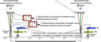
In order to reduce the magnitude of carried lightning overvoltages and protect the branches from the main line to the inputs to the structures, it is necessary to install an SPD. In this case, the following happens: lightning currents are discharged, as a rule, through a grounded drain, which is mounted on a power line support in the charger. A PEN conductor is connected to the grounding device, as well as hooks of phase wires and other wires that can be suspended on power line supports and reinforcement of reinforced concrete supports of overhead lines.
Grounding requirements must also be observed. No more than 30 Ohms - this should be the resistance of the grounding device, according to the instructions of regulatory documents.
In order to calculate the correct distance between power poles, you need to know the average statistics on thunderstorm activity in a particular region. If for the whole year the average duration of thunderstorms was up to 40 hours inclusive (region 1), then the value of 200 m is taken. But if the average duration of thunderstorms is more than 40 hours per year (region 2), the value of 100 m is used. Additional equipment for charger used for the following objects: – on power transmission line supports with branches into buildings in which large crowds of people may gather (hospitals, cultural and sports facilities, educational institutions, etc.) or for objects with great material value. Additional charger equipment is used on the end supports of power lines with branches. Here the distance to the nearest charger is taken into account. For region 1 this figure is no more than 100 m, and for region 2 it should not be more than 50 m. Low-voltage valve gaps or spark gaps are also used as additional protective measures at the entrances to buildings or at the end supports of power lines.
Figure 5. Valve arrester
Expected number of lightning outages of overhead power lines
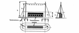
The expected number of lightning line outages is primarily determined by the intensity of lightning activity in the area of the line route. Based on average figures, it is generally accepted that there are 0.067 lightning strikes per 1 km of the earth’s surface in one thunderstorm hour. Taking into account the fact that the line absorbs all strikes from a strip 6h wide (h is the average height of a wire or cable suspension), the number N of lightning strikes on a line of length l per year is
N=0.067×n ×6h×l ×10-3,
where n is the number of thunderstorm hours per year.
The number of overlapping insulation of overhead power lines is determined by the formula
Nper = N x Pper,
where Pper is the probability of overlapping the line insulation at a given lightning current.
Not every pulsed insulation shutdown is accompanied by a line shutdown, since switching off requires the transition of a pulsed arc into a power arc. The transition probability depends on many factors, and in engineering calculations it is usually determined through the operating voltage gradient along the overlap path Eср = Urab / Lper, kV/m.
For lines on wooden supports with long air gaps, the probability of transition to a pulsed arc h is determined by the formula
For lines on metal and reinforced concrete supports h = 0.7 for line voltages up to 220 kV and h = 1.0 for rated voltages of 330 kV and higher.
By multiplying Nper by coefficient η, you can calculate the expected number of lightning line outages per year
In engineering practice, the specific number of line outages noff is usually used, i.e. the number of outages of a 100 km long line passing in an area with 30 thunderstorm hours per year:
To reduce the number of lightning line outages, you can:
- reduce the likelihood of insulation flashover during lightning strikes, which is usually achieved on overhead power lines with metal supports by suspending cable lightning rods and ensuring low impulse grounding resistance of supports and cables,
- lengthen the overlap path with a small operating voltage gradient, which reduces the coefficient h of the transition of the pulse arc to the power arc. The latter is implemented on overhead power lines with wooden poles.
Measures for internal lightning protection of overhead lines
Let's consider in practice how internal lightning protection of power lines is designed. SPDs, potential equalization systems or potential equalization (if necessary) and grounding devices are used as such equipment.
Figure 6. Internal lightning protection (overvoltage protection) on power lines
There is a classification of SPDs into categories, depending on the test method and installation:
SPD type No. 1 is installed at the air entry into the building. If an external lightning protection system for power lines is installed, then surge protection devices in this embodiment can be used to remove a significant part of the direct lightning current.
Induced current pulses also have a negative impact on the system; to prevent them, a second type of surge protection device is used. These devices are installed after the first type of SPD or at the entrance to the structure.
The purpose of the third type of SPD is to protect important electrical equipment, such as medical devices, data processing systems, etc. The third type of surge protection devices is located, as a rule, no more than 5 m along the cable from the devices that are to be protected. The third type of SPD is in practice mounted as a hidden installation, for example, the devices can be located directly behind the socket or in the device housing. The purpose of the delay line is to optimally distribute the pulse power between all levels of the protective system. In practice, a choke (15 µH inductance) is used. If there is no inductor, you can take a piece of cable (15 m or more in length) with the same inductance.
Initially, a first-class SPD is triggered; most of the pulse energy is spent on it. Then the SPD (class 2) reduces the voltage to a value that is recognized as safe.
Normative base
When designing, installing, operating and repairing overhead lines with voltages up to 1000 V, you should be guided by the following documents:
- Electrical Installation Rules (ELI), edition 6 and 7.
- GOST R 51992–2011. Low-voltage surge protection devices. Part 1. (IEC 61643 – 1:2005).
- STO 56947007–29.240.02.001–2008. Guidelines for the protection of electrical distribution networks with a voltage of 0.4–10 kV from lightning overvoltages. Standard of JSC FGC UES.
- Technical circular of the association "Roselektromontazh" No. 30/2012 "On the implementation of lightning protection and grounding of overhead lines and overhead lines up to 1 kV."
When choosing regulatory documents, priority should be given to GOSTs of the Russian Federation (or international standards, if they are in the rank of direct application), followed by Guiding Materials (RD), departmental instructions and manuals, which, as a rule, are of a reference or advisory nature, expanding and supplementing the standards in relation to specific industry conditions.
The design, installation, operation and repair of overhead lines should be entrusted only to specialized organizations that have the appropriate licenses (special permits) or to individual individuals (individual entrepreneurs) who have the appropriate certificates (diplomas) with the right of admission to work with the relevant electrical installations.
Do you need advice on organizing grounding and lightning protection for your facility? Contact the ZANDZ.ru Technical Center!