Why is the act needed, its meaning
Any cable, as a means that is intended to ensure the safety of current-carrying paths, is tested at the manufacturer before going on sale.
Here it is checked to what extent it complies with technical documentation, GOST and other standards, and after that a stamp is placed on its label indicating that it has undergone special control, which certifies that this cable product fully complies with current requirements.
However, after delivery to the construction or installation company, immediately before installation, the cable must also undergo an inspection, during which it is checked
- the tightness of its shell,
- no cuts, breaks, etc.,
- lack of communication between the cores,
- their connection with the screen or metal shell,
- compliance of cable insulation resistance with certain requirements, etc.
Based on the results of these control actions, the company’s specialists create a separate act.
This document plays a rather important role in preparing cables for installation. With its help, it is verified that the cables are in excellent condition, comply with all existing standards and do not have various types of flaws.
In construction and installation companies that have competently organized the preparatory work with materials, without this document the cable simply will not be allowed to be laid. And in those where the cable is not subject to such inspection, management risks incurring administrative punishment in the form of a fairly large fine in the event of visits from supervisory authorities.
Insulation resistance standards for various cables
The following types of electrical conductors are found:
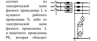
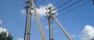
- High voltage - used at voltage levels above 1 kV. With their help, power lines are laid and power is supplied to six kilovolt electric motors. The permissible resistance value of the insulating layer is one mOhm per kV. For example, at a voltage level of 6 kV, the norm will be 6 mOhm.
- Low voltage - used in electrical circuits with voltages less than 1 kV. They are most often used for laying lighting networks and connecting 220 and 380 V electric motors. The minimum resistance value for the specified conductors is 0.5 mOhm.
- Control - designed for connecting measuring instruments, relay protection and automation devices, as well as for forming secondary switching circuits. For this category of wires, the lower insulation limit is 1 mOhm.
How is resistance measured?
The procedure for checking the condition of the insulating layer depends on the type of electrical conductor being tested. At the initial stage, identical actions are performed:
- The performance of the megohmmeter is checked. You will need to connect the two clamps of the device and take a measurement. The device should show zero. Then the ends of the wires of the measuring device are pulled apart and a measurement is taken. If the result is infinity, then the device is working.
- Measurements are taken from the side of the cable line where portable grounding is installed. During the work it is necessary to use dielectric gloves.
- At the other end of the cable line, the conductor cores should be spread apart. To ensure the safety of people from electric shock during testing, a person should be placed to warn of the danger.
At the final stage, it is necessary to compare the results obtained with acceptable values and draw up a protocol. It reflects the sequence of actions performed, the measuring instruments used, the temperature conditions and a conclusion about the condition of the electrical conductor.
Methodology for measuring insulation resistance of high-voltage power cables
It is necessary to ring high-voltage conductors using a 2500 V megohmmeter. The sequence of actions is as follows:
- One end of the measuring device clings to the ground loop, and the other to phase “A” of the cable.
- The grounding conductor is removed from phase “A” and measurements are taken for 60 seconds.
- Next, you will need to install the grounding to phase “A” and remove the megohmmeter clamp.
- In the future, similar operations are carried out for phases “B” and “C”.
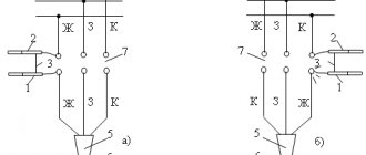
High voltage cable insulation measurement circuit
For a significant cable line length, tests are carried out taking into account the absorption coefficient. You will need to record the device readings after 15 and 60 seconds of measurements. The ratio of the resistance value after 60 seconds to the reading after 15 seconds must be at least 1.3. If the value is lower, it is concluded that the insulating layer is moistened. To eliminate the problem, you will need to dry the conductor.
Methodology for measuring insulation resistance of low-voltage power cables
To carry out the work, you will need to use a 1000 V megohmmeter. After completing the initial steps, you must begin the following activities:
Who inspects the cable?
Cable inspection is carried out by company specialists who have permission to work with cable lines. In other words, these must be persons who have undergone special training, successfully passed exams and, based on the results of certification, received a certificate to perform work with cable networks. At the same time, craftsmen must periodically confirm their qualifications.
It is the responsibility of these same employees of the organization to draw up a report based on the results of the cable inspection, for the contents of which they bear full responsibility.
You should be very careful when drafting this document, avoiding inaccuracies and errors, and even more so introducing obviously incorrect information into the document. It is important to remember that in the future, if something suddenly happens to the cable during operation, all responsibility for this can be assigned to those who approved it before use.
Procedure for checking cable insulation resistance with a megohmmeter
You come to the site and see, for example, the following picture.
Before directly checking the insulation resistance, you must make sure that:
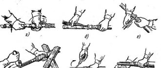
- The cable cores are ringed and marked (read about ringing here)
- on the cable cores where we will supply voltage there is no dirt, scale, or paint (there is no such thing on the cable core, but it may be on the grounding, which is painted, or it may be covered with a layer of rust, then you need to scrape it off with a screwdriver or knife)
- at the other end of the cable no one is working and the cable is disconnected from the load and the power source (it is not worth applying voltage to the installer, who can cut the cable from the other side, or measuring the Rx of the cable with the load, it is also worth making sure that we do not apply high voltage to the secondary circuits and elements that can become unusable at 2500V, so sometimes they are simply switched to 500V)
- the cable is de-energized and measures are in place to prevent accidental supply of voltage to the cable under test (locks, posters, cells removed)
- if the vigilante test (measurement of insulation resistance) is combined with high-voltage tests, then you need to make sure that there is a person at the second end of the cable (the second end is opposite from the test site) or the room is locked and fenced with posters posted
- The megohmmeter is in good condition and suitable for use (verification mark on the body and the ends of the device are tested)
- you have the right and qualifications to work with a megohmmeter and perform this type of work (group 3 on electrical safety and an unexpired test of special knowledge, plus a medical examination)
- the megohmmeter wires must have high insulation (here you can also do the following: connect the two megohmmeter wires and apply voltage - the value should be zero, since there is no insulation between the wires, and if you separate them, then infinity - since the air resistance is high)
Format and execution of the act
This act, like any other similar document, today can be written in free form - there is no single standard. But in those companies that have developed their own unified model, this should be used.
The same applies to the answer to the question of whether it is possible to write the act by hand: both handwritten and printed versions of the act are acceptable.
The document must be signed by all persons who were present during the inspection of the cable - thus, they will certify the fact that all the data entered in the form is reliable.
With regard to printing, everything depends on whether this stamp product is used in the current activities of the company - if there is a condition for its use in such papers, then the act should be stamped.
The act, as a rule, is made in one original copy, but if there is a need for additional copies, the document can be duplicated.
The finished act is subject to mandatory registration in a special accounting journal (where it is enough to enter its number and date of production).
The act must be stored in accordance with the requirements of the law or the company’s internal regulatory documents (but not less than five years).
Control cable testing
Before laying secondary circuits, control cables are prepared in accordance with the required lengths. The ends of the cables are sealed, after which the cables are wound onto inventory drums and delivered to the installation site.
Checking the integrity of the cores and compliance with their markings
The cables are laid out along the route and tested for wire breaks and correct markings. The test is performed using handsets and power sources (electric batteries or accumulators) and an intercom.
Two people are required to carry out the test. At both ends of the cable, the handset is connected at one end to the power source. The second pole of the electric battery or accumulator is grounded. If the control cable has armor or shielding, these must also be grounded. To create an electrical circuit, handsets must be connected to opposite poles of the power source. The check is carried out as follows:
- at one end of the cable, the second end of the tube is connected to one of its cores;
- the first worker tells his partner via the intercom the number or color of the core in the bundle
- the installer, located at the second end of the control cable, begins to touch the cable cores with the same markings one by one;
- a click in the handset indicates the integrity of the core;
- identical cores are marked;
- the check continues until all relevant cores are found, after which the circuit is installed according to the diagram.
According to the requirements of paragraph 2.6.15 of the “Rules for the technical operation of consumer electrical installations,” the cores of control cables must be marked at the ends, at branch points, when the line passes through building partitions (walls and ceilings).
To find identical current-carrying wires by one worker, the PZh-30 device can be used.
After this, measurements of the insulation resistance of current-carrying conductors and testing of control cables with increased voltage are carried out.
Insulation resistance measurement
These tests are carried out to assess the condition of the control cable and monitor the safety of the secondary circuits. The frequency of measurements is regulated by the operating rules of specific electrical installations and must be carried out at least once every three years. In outdoor electrical installations or installations operated in particularly hazardous conditions, including freight and passenger elevators, as well as in cranes, cable inspections are carried out at least once a year. Tests are carried out without disconnecting the conductors from the terminals or clamp assemblies.
Depending on the specification of the control cables, analog or digital megohmmeters with operating voltages from 500 to 2500 V are used to measure insulation resistance. Before starting measurements, the device is calibrated as follows:
- when the probes are closed and voltage is applied, the arrow is set to “zero”;
- with the probes open and voltage applied, the arrow should show infinity.
The rotation speed of the handle of megohmmeters with a built-in generator should be uniform and range from 120 to 150 rpm.
Algorithm for testing control cables :
- The absence of voltage is checked. To remove residual voltage, the current-carrying conductors of the cable are grounded;
- all conductors except the test one are combined with each other and grounded. Armor or shielding is also subject to grounding if they are present in the cable design;
- the positive (“+”) output of the megohmmeter is connected to the core being tested, and the negative output is connected to the grounded wires;
- a test voltage is applied to the cable for one minute, the results of which are recorded in a log;
- The residual voltage is removed from the core being tested, and the process is repeated with the next cable core until the resistance of all cores has been measured.
The insulation resistance of the cores must not be less than the values indicated in the table.
High voltage test
Testing of control cables with increased voltage is carried out in secondary circuits with an increased probability of short circuits between current-carrying conductors, which can cause emergency situations with serious consequences. Tests are carried out without fail after installation and restoration of secondary circuits, and also if the insulation resistance identified during the previous study does not correspond to standard values. The test duration is one minute at a voltage of 1000 V with a current frequency of 50 Hz.
To carry out the tests, a voltage transformer of type NOM-10 or NOM-6, a control unit of type K513 or LATR, and a voltmeter with a sufficient measurement limit are used.
High voltage test algorithm:
- armor or shields are grounded on both sides, if they are included in the structure;
- on the tested side of the cable, one of the cores is taken to the side, and the rest are combined with each other and grounded;
- the voltage on the tested core slowly rises to a value of 600 V;
- the output voltage is measured and current leakage is checked;
- if there are no visible breakdown points, the voltage rises to the nominal value and is maintained for one minute;
- After the test time has expired, the voltage gradually decreases to zero.
The insulation passed the test if no sliding discharges occurred during the entire test, and there were no insulation breakdowns or current leaks. All other cable cores are checked according to the described algorithm.
If a breakdown is detected, it is necessary to repair the insulation damage and re-test with increased voltage. In some cases, the insulation resistance is re-measured and the results are compared. If the differences are minimal, then the cable has passed the test.
Sample inspection report for the cable on the drum before installation
If you need to draw up an inspection report for a cable on a drum before installation, which you have never done before, look at the sample below, and also read the explanations for it. They will help you make the desired form with minimal edits and without any problems.
- The first part of the document is without any special features: write here the name of the organization, then assign a number to the act (as necessary), note the date and place of its preparation.
- Further information is best presented in the form of a table. Enter the drum number, the cable brand and its identification parameters, the length of the cable line, and the name of the manufacturer.
- Include columns here that will contain information about the condition of the drum and its casing, outer coils, and caps.
- Indicate in the report the data based on the results of the insulation resistance test and give a conclusion to the procedure performed.
- Below the table you should indicate which instruments were used to test the cable.
- The act can also be supplemented with other information that you consider important.
- Finally, put all the necessary signatures on the document.
Storing cables in drums and testing them
Before delivery
to the installation site, the entire length of the cable must be subjected to visual inspection and, if the need arises, to various tests and measurement checks. A visual inspection makes it possible to verify the integrity and serviceability of the drums, bushings, casing, as well as the quality and reliability of the termination of the wire ends.
In addition, specialists should also check the availability of the technical passport and the compliance of the data in it with reality. Based on the results of the inspections and studies carried out, a cable inspection report on the drum must be drawn up.
Current regulatory documents indicate the need to store all low-frequency cables of more than 100 pairs and intended for organizing connections between stations on special cable platforms that are under constant excess pressure. The level of excess pressure in such storage areas, as well as other external conditions, for example, air temperature during testing, must be indicated in the technical data sheet for each construction length. The technical data sheet for the cables must be placed in a moisture-proof envelope and secured to the inside of the drum cheek. The exact location of the passport in the drum is indicated by a mark on its outer surface.
It is also worth noting that one of the accessible ends of the cable must be equipped with a special air valve with a lock and a cap, or a sealed pipe, necessary for connecting a pressure gauge to the drum and checking the exact parameters of the excess pressure.
Based on a visual inspection and checking the excess pressure in the cable, specialists decide on the need to conduct additional research and measurements to identify a possible discrepancy between the quality of the wire and the parameters described in the passport and regulatory documentation before carrying out electrical installation.
Measuring cable insulation resistance with a megohmmeter
The procedure is as follows (CABLE DE-energized):
- One end of the megohmmeter is connected to ground for the duration of the test (this can be a grounded busbar, grounding bolt or portable grounding)
- If there is a shell, screen, armor, they should also be grounded during the insulation resistance measurement and high-voltage test
- We attach a grounding connection to the cable core being tested (this removes possible residual charge on the cable)
- We hang the second end of the megohmmeter on the core being tested, through which a voltage of 2500V will be supplied.
- We remove the ground wire from the tested core
- Apply the device to the tested core with a voltage of 2500V for 60 seconds. We record the insulation resistance value at the 15th and 60th seconds of the test (in the case of an electronic device with a memory, the values may not be recorded)
- We attach a grounding connection to the tested cable core in order to discharge the cable. The longer the cable, the longer you need to keep the ground wire on the core.
- We remove the second end of the megohmmeter from the tested core, then move to another cable core and go from point 2). Then do the same for the third core. Finally, disconnect the device from the electrical installation.
If we have a three-core cable, then we must obtain the phase-to-zero and phase-to-phase insulation resistance values. Total 6 measurements. In reality, they do not make three measurements, but one - they combine three wires and apply voltage from the megohmmeter to them. If the insulation resistance value is satisfactory, then everything is fine. If Rx is unsatisfactory, then each core is measured separately.
Record readings at 15 and 60 seconds to determine the absorption coefficient (Ka). This coefficient is numerically equal to the ratio of resistance values R60/R15. Shows the degree of moisture. There is also the concept of polarization coefficient or polarization index (PI) - it is equal to the ratio R600/R60 and characterizes the degree of aging of the insulation. The standards define the following values:
The limit value indicates that the cable is unsuitable for use. The polarization index is measured on cables with impregnated paper insulation along with Ka. For cables with plastic, PVC, or cross-linked polyethylene insulation, there is no need to determine the polarization index.
Now there are various digital and electronic megohmmeters. In digital ones you can immediately see after measuring the values of the absorption coefficient, R60, R15; separate devices allow you to measure PI. In addition, for sonel models you can press the start button, then use another button to lock it and not hold your finger on the button for a minute. The devices operate on batteries. It makes life easier.
In pointer instruments, the source of constant voltage (and tests with a megohmmeter are tests with constant voltage) is based on either a generator or a button (ESO models).
Here you will either have to turn the handle of the device at a speed of 2 rps, or look for an outlet. And besides this, you still need to count down the stopwatch and record the results. The scales of individual instruments also cause difficulties. But megaohmmeters from various manufacturers are the topic of a separate large article.
In general, do not forget to discharge the cable after testing, removing the accumulated charge by grounding. And only then remove the end of the device from the core being tested. And the longer the cable, the longer you keep it grounded.
Bookmark or share with friends
>