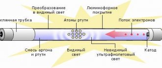
Structurally, fluorescent lamps are a glass bulb, the inner surface of which is coated with a special compound - a phosphor. It consists of calcium halophosphate and other impurities, some versions contain rare earth elements - terbium, europium or cerium, but such combinations are quite expensive.
At the manufacturing stage, all air is pumped out of the flask, and the container is filled with a mixture of inert gases, most often argon, and mercury vapor. Depending on the lamp model, the chemical composition of both inert gases and phosphor will differ. Inside the gas mixture there is a tungsten filament, which is covered with an emitting coating.
The principle of operation of such an energy-saving lamp is the following sequence of electrochemical processes:
- A supply voltage is applied to the contacts of a gas-discharge mercury lamp, due to which an electric current begins to flow in the incandescent filament circuit.
- When an electric current flows, thermal energy and emitter particles begin to spread from the surface of the thread, which activate the inert gas and cause the release of ultraviolet radiation.
- The glow of gases has a relatively low percentage of the visible spectrum, since most of it falls on ultraviolet waves. But when the ultraviolet reaches the glass bulb of the gas-discharge lamp, the phosphor is activated and subsequently glows.
The emission spectrum of fluorescent light bulbs can vary over a fairly wide range. The choice of shades of glow in lighting devices is carried out by changing the percentage of magnesium and antimony in the composition of the phosphor.
Also an important point is the temperature indicator, therefore the magnitude of the applied voltage and the flowing electric current must have a constant value for each diameter of the flask. It is strict adherence to the electrical characteristics in relation to its geometric parameters in a fluorescent lamp that allows it to produce the desired color and brightness of the glow.
Expert opinion
It-Technology, Electrical power and electronics specialist
Ask questions to the “Specialist for modernization of energy generation systems”
Connection diagram for a fluorescent lamp with a choke and a starter, with two G pin lamps, in which the number after the letter marking shows the distance between the contacts, and before the number of pairs of contacts. Ask, I'm in touch!
Fluorescent lamp: device, principle of operation, types, markings
- Sufficiently high efficiency, in comparison with the same incandescent lamps they produce an order of magnitude greater luminous flux for each watt of electricity consumed;
- It has several color spectrum options, which makes their use justified for various purposes;
- The service life before failure is 10–15 times higher than that of incandescent and halogen lamps;
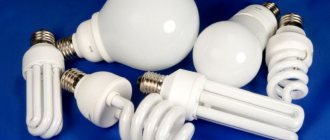
- Quite a wide variety of designs - compact, large, elongated, etc.
Electrical circuits of table lamps
The simplest electrical circuit \Fig. 1\, both for table lamps and for various models of sconce lamps, has a comparison with this electrical circuit:
Fig.1
This electrical circuit is more suitable for the electrical circuit of sconce lamps, but it also applies to the electrical circuit of table lamps.
Let's take for example the electrical circuit on the right - such a circuit is quite suitable for both a table lamp and a sconce lamp, consisting of:
- two lamps;
- key\switch\.
Varieties
The entire variety of fluorescent lamps is characterized by a fairly wide range of parameters. But in this article we will look at the most distinctive of them.
What kind of lighting do you prefer?
Built-in Chandelier
In practice, high- and low-pressure lamps are distinguished according to the gas pressure inside the bulb:
- High pressure - such luminescent devices produce a dense light flux in rich color shades. They are used in fairly powerful models with a rating from 50 to 2000 W, characterized by a service life of 6 thousand to 15 thousand hours.
- Low pressure - characterized by a relatively low density of gas in the container, used for lighting premises in the home or in production.
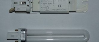
According to the shape of the bulb of an energy-saving light bulb - the bulb can have a classic pear-shaped shape with a glass spiral inside, an oblong elongated shape, the appearance of a spiral tube twisted around an axis, ring-shaped and other shapes.
Based on the design of the base, fluorescent lamps are distinguished with a standard base E with a numerical designation indicating the diameter of the base of the gas-discharge source. G – pin, in which the number after the letter marking shows the distance between the contacts, and before the number of pairs of contacts. You can also find models with W and F type bases, but they are used quite rarely.
Based on the color temperature of the glow, fluorescent devices with a hot yellow and cold blue spectrum are distinguished. There are also options for neutral glow colors. Color temperatures are selected in accordance with the tasks: warm for housing, cold for industrial facilities.
Rice. 4. Color temperature
Principle of operation
A fluorescent light bulb is a gas-discharge light source in which a discharge of electricity in mercury vapor produces ultraviolet radiation. Due to exposure to ultraviolet light, a glow appears using a phosphor.
The operating principle of the lamp is shown in the diagram below:
Digital symbols on the diagram:
- stabilizer (ballast control device);
- lamp tube (includes electrodes, gaseous medium and phosphor);
- phosphor layer;
- starter contacts;
- electrodes;
- starter cylinder;
- bimetallic plate;
- flask filler (inert gas);
- filaments;
- ultraviolet radiation;
- breakdown.
Note! The phosphor layer is necessary to convert ultraviolet light. If you change the composition of the layer, you can get the desired shade of light.
Connection methods
There are various options for connecting a fluorescent lamp to the network. The most popular scheme for a fluorescent lamp is connection using an electromagnetic ballast.
Circuit with electromagnetic ballast (EMB)
- High energy costs compared to other methods.
- Long startup time - approximately 1-3 seconds. The more worn the light bulb is, the longer it will take to light.
- Does not work at low temperatures. This makes it impossible to use in a basement or garage that is not heated.
- Stroboscopic effect. Flicker negatively affects human vision and the psyche, so such lighting is not recommended for use in production.
- Humming noise when working.
The circuit provides one choke for two light bulbs. Its inductance is enough for both light sources. The starter voltage is 127 V; for a lamp with one lamp, a voltage of 220 V is required.
There is a circuit for a 220 V fluorescent lamp with a chokeless connection. It does not have a starter. This starterless connection is used when the filament of a light bulb burns out. The design also includes a transformer and a capacitor to limit the current. For lamps with a burnt-out filament, there are circuit modifications without a transformer. This makes the design easier.
Two chokes and two pipes
This method is used for two lamps. The elements must be connected in series:
- Phase - to the inductor input.
- From the throttle output, connect one contact to the first lamp, the second to the first starter.
- From the first starter, the wires go to the second pair of contacts of the first lamp, the free wire must be connected to zero.
Connecting two lamps from one choke
This option is not used often, but it is not difficult to implement. The two-lamp serial connection is distinguished by its economy. For implementation, you will need an induction choke and a pair of starters.
Connection diagram for fluorescent lamps from one choke:
- A starter is connected to the pin output of the lamps using a parallel connection.
- Free contacts are connected to the electrical network through a choke.
- Capacitors are connected in parallel to the light sources.
Budget switches may periodically stick due to increased starting currents. In this case, it is recommended to use high quality switching devices. This will ensure long and stable operation of the fluorescent lamp.
Circuit with electronic ballast
All the disadvantages of the EMPA led to the fact that I had to look for another connection method. As a result, the electromagnetic ballast was replaced with an electronic one, operating not at the mains frequency of 59 Hz, but at a high frequency of 20-60 kHz. Thanks to this solution, flickering of the light is eliminated. Such schemes are used in production.
Expert opinion
It-Technology, Electrical power and electronics specialist
Ask questions to the “Specialist for modernization of energy generation systems”
About power supply systems for fluorescent lamps | BUDYON S OFFICIAL SITE If you are remaking an old lamp from the times of the Soviet Union with a starter and electromagnetic ballast, virtually no modernization is required. Ask, I'm in touch!
Repair and circuit design of energy-saving lamps.
Energy-saving lamps, or compact fluorescent lamps (CFLs), can be divided into two parts: 1) - the fluorescent lamp itself 2) - an electronic ballast (electronic ballast), built into the lamp base. Let's take a closer look at what's in the electronic ballast:
— Diodes — 6 pcs. High-voltage (220 Volts) are usually low-power (no more than 0.5 Amperes). - Throttle. (removes network interference). - Medium power transistors (usually MJE13003). — High voltage electrolyte. (typically 4.7 uF at 400 volts). — Ordinary capacitors of different capacities, but all at 250 volts. — Two high-frequency transformers. — Several resistors. Let's look at the operation of an energy-saving lamp using the example of the most common scheme (11W lamp).
The circuit consists of power circuits that include noise-protecting choke L2, fuse F1, a diode bridge consisting of four 1N4007 diodes and filter capacitor C4. The triggering circuit consists of elements D1, C2, R6 and a dinistor. D2, D3, R1 and R3 perform protective functions. Sometimes these diodes are not installed in order to save money. When the lamp is turned on, R6, C2 and the dinistor form a pulse applied to the base of transistor Q2, leading to its opening. After startup, this part of the circuit is blocked by diode D1. After each opening of transistor Q2, capacitor C2 is discharged. This prevents the dinistor from opening again. The transistors excite the transformer TR1, which consists of a ferrite ring with three windings of several turns. The filaments receive voltage through capacitor C3 from the boost resonant circuit L1, TR1, C3 and C6. The tube lights up at the resonant frequency determined by capacitor C3 because its capacitance is much smaller than that of C6. At this moment, the voltage on capacitor C3 reaches about 600V. During startup, peak currents are 3-5 times higher than normal, so if the lamp bulb is damaged, there is a risk of damage to the transistors. When the gas in the tube is ionized, C3 is practically bypassed, due to which the frequency is lowered and the oscillator is controlled only by capacitor C6 and generates less voltage, but nevertheless sufficient to keep the lamp glowing. When the lamp lights up, the first transistor opens, which leads to saturation of the TR1 core. Feedback to the base causes the transistor to close. Then the second transistor, excited by the oppositely connected winding TR1, opens and the process repeats.
Malfunctions of energy-saving lamps
The most common causes of failure of energy-saving lamps are filament breakage or electronic ballast failure. As a rule, the cause of failure of the latter is a breakdown of the resonant capacitor or transistors. Capacitor C3 often fails in lamps that use cheap components designed for low voltage. When the lamp stops lighting, there is a risk of failure of transistors Q1 and Q2 and, as a result, R1, R2, R3 and R5. When the lamp starts, the generator turns out to be overloaded and the transistors cannot withstand overheating. If the lamp bulb fails, the electronics usually also break down, mainly power transistors burn out. If the bulb is already old, one of the spirals may burn out and the lamp will stop working. Electronics in such cases, as a rule, remain intact. Most often, lamps burn out the moment they are turned on.
As a rule, the lamp is assembled with latches.
You need to disassemble it:
Turn off the flask:
We check the filament of the bulb with an ohmmeter.
Replacing fluorescent lamps
The fluorescent light source differs from classic halogen lamps and products with filament in its long service life. But even such reliable light bulbs can fail, which is why they have to be replaced.
- Disassemble the lamp. It is important to carefully remove all parts so that the device is not damaged. The fluorescent tubes must be rotated around their axis in the marked direction. It is indicated on the holder by arrows.
- After turning 90 degrees, the tube should be lowered. Then the contacts will easily come out of the corresponding hole.
- Visually inspect the integrity of the light bulb and filaments. If there are no visual problems, the failure may be caused by internal components.
- You should take a new light source. Its contacts must be in a vertical position and placed in the hole. After installing the light bulb, you need to turn it in the reverse position.
You must remove the device carefully so as not to break the glass flask. There is mercury inside, which is hazardous to health.
After the system is assembled, you can apply the supply voltage, turn it on and begin testing. The final step is to install a protective shade on the lamp.
Useful tips Connection diagrams Principles of operation of devices Main concepts Meters from Energomer Precautions Incandescent lamps Video instructions for the master Testing with a multimeter
Recommendations
If there is no response to switching on, before starting to look for a fault, it is recommended to measure the voltage at the input terminals. If present, look for the fault in the following order:
- Rotate the lamps slightly around their axis. In case of precise installation, the contacts are located parallel to the plane of the lamp. The correct position can be determined by feeling the force when putting it in place.
- Replace the starter with a working one. Specialists who service many lighting devices with fluorescent lamps always have a known working starter with them. If this is not available, it is better to take it from an existing lamp for testing.
- Test the performance of the lamp. If the lamp has two lamps, then this is not difficult to do. Otherwise, you will have to find a working lamp elsewhere.
- Measure the resistance with a multimeter.
- If the lamp and starter are in good condition, the throttle is checked. A multimeter or a simple indicator screwdriver will help for this. When checking, the phase must be at the output and input. If in doubt, the throttle is replaced.
- Next, the absence of defects in the wiring of the lamp is checked. It is advisable to remove the lamp to check it. All contact connections of the throttle, cartridges and starter are checked.
Dimmer purpose
The purpose of a dimmer is to change the brightness of lighting devices. Adjustable light switches allow you to achieve any lighting intensity: from dim light to extremely bright. The use of dimmers makes double or triple switches unnecessary, and there is no need to buy expensive lighting fixtures with voltage controllers.
Note! To control the light intensity of energy-saving light bulbs, you will need a special device - an electronic starter.
The advantages of dimmers include the following characteristics:
- light brightness control;
- setting the brightness change time;
- remote control control;
- long service life;
- programmed artistic flickering, creating backlit paintings;
- economical energy consumption (some models).
- excessive electricity consumption in some cases;
- creating radio interference that interferes with the operation of electrical appliances;
- small loads cause dimmers to malfunction;
- The operation of dimmers often leads to unwanted flickering of the light.
Requirements for installing a dimmer
When installing a dimming device, you should pay attention to several important circumstances:
- Fluorescent and energy-saving lamps are not dimmable in the standard way. Both types of light bulbs can work with a dimmer, but their service life is sharply reduced. Sometimes the life of a light bulb is reduced to 100–150 hours. In addition, the risk of damage to the dimmer itself increases.
- Dimmers require a certain minimum load. Most often its value is 40 watts. A decrease in load occurs due to the burnout of one of the light bulbs, deterioration of contacts, and the appearance of flickering with a frequency of 50 hertz. When the load drops below the minimum permissible, the protective system is triggered or the device becomes faulty.
- Dimmers are sensitive to ambient temperature conditions. At temperatures above 25 degrees, overheating is possible, which can lead to damage to the dimmer.
- The maximum permitted load on the device should not be exceeded. If necessary, it is recommended to add power amplifiers, which can be used to switch devices up to 1.8 kilowatts.
- Capacitive and inductive loads cannot be connected at the same time. This can cause damage to the device.
As for the installation location, experts recommend proceeding from the following information:
- Dimmers should not be installed in rooms where there are usually a lot of people. In crowded areas, the equipment will operate with interference.
- It is necessary to avoid installing dimmers in rooms where there is no permanent place for installing lighting equipment.
Repairing or replacing a lamp socket or chandelier
Let's say the cartridge crumbles or the contacts are so rusty that there is no point in cleaning them. In this case, it is recommended to replace the cartridge. The photo shows options for purchased electrics:
Disassembling the lamp
In front of us lies a typical white ceramic flat mount socket (left). Structurally becomes part of a bathroom wall lamp
Note the relatively strong isolation of the node. If necessary, such a cartridge can be purchased for a price of 30 rubles and replaced with the old one. Black sockets are also structurally included in the inclined type lamp, but for the pantry
It is not forbidden to install one under the ceiling of the bathroom, but if the neighbors flood it, such an installation will not lead to anything good. Notice the design on the right. Inclined chuck without back wall. We found a chandelier backdrop and showed that the parts fit together perfectly. It is not necessary to buy the cartridge separately; purchase it as part of the electrical part of the lamps. In stores, instead of the usual black cartridges, readers will be surprised to find mostly white ones - plastic and ceramic. In terms of size and design, they were not close to the usual ones. When modifying the socket of a chandelier or lamp, the work will increase: usually the backdrop is attached to a threaded connection (seen in the photo), which does not fit the diameter of the new standards. You will have to finish it with a file, which is long, tedious and does not guarantee a successful outcome. Our technical solution looks better, although the inclined lamp is a little more expensive than the socket separately.
Types of cartridges
It can be useful to clean the cartridge contacts. Do this with fine sandpaper. The procedure is aimed at reducing contact resistance. In this case, ignition is simplified
Please note that halogen lamps often blink several times before starting. This does not indicate the need to repair the lamp, but simply indicates the design features of gas-discharge sources
Wiring diagram for Chinese touch switch
So how do the wires connect to this miracle box? First of all, focus on the inscriptions and symbols on the case.
One of the power wires must be interrupted by a switch. Because of this, the lamp actually does not light up.
In this case, it does not matter which wire it is: phase or neutral. After all, as soon as you insert the other side of the plug into the socket, the “timings” will immediately change
In general, connect the conditional phase cable from the power cable to the voltage supply cable to the sensor (black - black).
Connect the neutral from the network to the other power wire of the sensor - red (red). That is, the red and black wires from the box go to the 220V outlet.
White (white) and again black (black) are connected by two wires going to the lamp.
According to the diagram, you need to connect the three ends in one place:
conditional zero from the network
ZERO for sensor
ZERO on the light bulb
The phase is interrupted through the sensor and goes to the lamp with a separate conductor. If you're completely confused, here's a clearer picture.
The general connection diagram is as follows.
After twisting the wires, all contacts must be soldered.
And then wrap it with electrical tape or apply heat shrink.
Everything can be connected to PPE (insulating plugs).
Useful tips
Some practical tips for lamp repair:
- Do not put pressure on the light bulb when screwing it into the socket. The base is made of ductile metal that deforms under pressure. However, halogen bulbs have circular contacts, so they are difficult to damage.
- Halogen lamps rotate endlessly. From a certain moment, when rotating, the glass begins to scroll relative to the base. The problem is the contacts. The new lamps have a shorter thread and do not reach the bottom.
- If the switch is in the off position, the phase should not be directed to the cartridge contacts. If this is not the case, you need to turn off the circuit breaker in the electrical panel (at the entrance).
To create contact between the lamp and the base, perform the following steps:
The central contact is turned upward using a screwdriver. The contact pad should be at an angle, not vertical. The lunar contact is usually vertical
Any of the existing petals is carefully lifted (at least a millimeter), focusing towards the periphery of the cartridge. The bent ends are slightly straightened.
Most often, two or three fittings are enough for the lamp to turn on.
Particular attention should be paid to maintaining the edges of the cartridge, otherwise it will have to be replaced
Source
How does our company approach the repair of floor lamps and sconces?
You need to call us at the numbers listed on the website and ask the consultant everything you need: cost of services, operating hours, speed of order fulfillment, and so on. Or immediately bring your floor lamp or sconce to our workshop. Our employees fulfill orders within the agreed period.
Type Diagnostics Master's work
Floor lamp or sconce 350 rub. from 1500 rub.
We also have our own warehouse of lighting elements; if you wish, we can provide spare parts and lamps for your lamp.
Tell me what doesn't work
Address of the service center in the Northern Administrative District: Moscow, Khoroshevskoe highway, 24. Begovaya metro station, 2 minutes on foot.