In the context of constant growth of tariffs for the use of electricity, the population's demand for more economical fluorescent lamps (fluorescent lamps) has increased significantly.
There are quite a lot of options for their appearance, however, they are all built the same inside.
Inside the glass flask, whatever its shape, there are:
- An inert gas with mercury vapor.
- Spiral electrodes. Luminescent coating (luminophor) applied to the walls of the flask.
The principle of operation is as follows: under the influence of electric current, the spirals (electrodes) heat up and ignite the gas, under the influence of which the phosphor begins to glow.
Due to the limited size of the electrodes, the household power supply voltage is not enough to ignite them. Therefore, to ignite the electrodes, a special element is used - a choke. In addition, to avoid overheating of the coil, another element is used - a starter, which, after igniting the gas, turns off the heating of the electrodes.
Structurally, the inductor (EMPRA) is an inductor with a special ferromagnetic core. As a rule, the coil with the core is placed in a metal case.
What is a throttle, appearance and device
A choke is a type of inductor; it is a special copper wire wound around a core. But not everything is so simple, they also come without a core, called frameless or air. Outwardly, some look like a transformer. The difference is that the inductor has only one winding, while the transformer has two or more. If there are only two outputs, then this is definitely not a transformer.
Coreless chokes are wire wound in a spiral. We’ve figured out what a choke looks like in electrical engineering, now let’s talk about its design.
What is a choke: it is copper wire wound in a spiral with or without a core
As has already been said, the inductor may or may not have a core. The core can be made of a conductive material - metal, or maybe magnetic. The presence or absence of a core, as well as its type (not only material, but also shape) affect the parameters of the inductor.
Elements without cores are used to cut off high frequencies, while elements with a core are often used for energy storage. There is one more point: if you compare chokes with the same parameters with and without a core, then those that have one are much smaller in size. The better the conductivity of the core, the less wire there is and the smaller the element has dimensions.
Schematic representation of a choke with and without a magnetic core
A few words about the wire that is used to wind the inductor. This is a special insulated wire. Insulation is a thin layer of dielectric varnish, it is invisible, but insulates well. So, when winding a coil yourself, do not use regular wire, only special wire coated with insulation.
The choke in the diagram is indicated by a graphical representation of a half-wave. If it has a magnetic core, a dash is added. If any special metal is required, this is also indicated next to the schematic illustration. The wire diameter (L1) may also be indicated.
What is a throttle for?
First, let's define what a throttle is or what is also called ballast. Essentially, this is an ordinary inductor with a ferromagnetic core.
Here's what it looks like in the section.
In circuits, ballast is needed for three functions:
- check the current to ensure it does not exceed the rated current
- formation due to inductance of a short-term pulse of increased voltage
- possible smoothing of ripples in the 220V network
it is connected in series and a starter is mounted in parallel with it.
A starter is required to light the lamp.
Properties, purpose and functions
Now let's look at what a throttle is from an electrical point of view. In short, this is an element that smoothes the current in the circuit, which is clearly visible in the graph. If we apply alternating current to it, we will see that the voltage on the coil increases gradually, with some delay. After the voltage is removed, current continues to flow in the circuit for some time. This happens because the coil's field continues to "push" electrons thanks to the stored energy. That is, the current in the inductor cannot appear and disappear instantly.
The current through the inductor increases smoothly and decreases just as smoothly. Looking at these graphs, it becomes clear that the inductor is an element that smoothes the current
This property is used when it is necessary to limit the current, but there are heating restrictions (it is advisable to avoid it). That is, the inductor is used as an inductive reactance that delays or smoothes out current surges. Like a resistor, an inductor has a certain resistance, which causes a voltage drop and limits the current. It just heats up a lot less. Therefore, it is often used as an inductive load.
The inductor has two properties that are also used in circuits.
- since it is a subtype of inductor, it can store charge;
- cuts off current at a certain frequency (the delayed frequency depends on the parameters of the coil).
In some devices (fluorescent lamps), a choke is installed specifically to accumulate charge. In all kinds of filters it is used to suppress unwanted frequencies.
Broken winding of the electric coil. How to check the coil and find a break.
Topic: what to do if the coil winding breaks, how to check for a break.
When an electrical winding through which current flows breaks, one or another device usually fails (since any windings usually play an important functional role in the operation of electrical devices).
Let's look at this problem more carefully, finding out the important points for ourselves. So, in most cases, copper wire winding is used in transformers, electric motors and electric generators, valves, electromagnets, relays, contactors, inductors, etc. The most significant physical effect that electric coils have is the induction of electromagnetic fields. It is when an electric current flows through a wire winding that a fairly intense electromagnetic field is formed around it, which makes it possible to influence both mechanical movement and the generation of electromotive force (induced on another winding located nearby). Consequently, when the winding breaks, the contact is broken and the movement of the electric current stops, as a result of which the processes of interaction with electromagnetic fields stop. How can you calculate a winding break? Having checked it for integrity, having previously rung it with a tester. But it's not that simple. It’s one thing when the electrical winding simply breaks as a result of scorching or mechanical damage. And another thing is the case when the device containing the winding is subjected to periodic overheating. As a result, the quality of the insulating cover of the winding is impaired (gradual destruction of the insulating varnish occurs). This leads to the appearance of short-circuited turns, which contributes to even greater heating of the coil with subsequent failure. That is, the wire burns out (or the entire winding burns out) and the coil breaks.
If an electric coil with a winding is located on the device, to check it it is necessary to unsolder it (to prevent continuity through other electrical circuits of the device). And only when the winding is not electrically connected to other circuits can it be tested with an internal resistance tester. If it is there (in the absence of short-circuited turns), then everything is fine with your winding, it is working. If the continuity tester does not show resistance, the value of which depends on the length of the winding wire, its cross-section, material (although copper is mainly used), then your winding has a break.
Based on practice, a fairly large number of winding breaks are associated with the following reasons - poor soldering of the ends of the winding to the terminal terminals of the device, burnout of the wire in the most vulnerable places (places of frequent bending, previously mechanically damaged), accidental mechanical damage due to improper operation, preventive maintenance, overheating devices with windings for short circuits and current overloads.
Most often, a winding break is located at the location of the terminals of this very winding, the place where they are soldered to the wire, extending these same terminals. Such breaks are easy to find and eliminate; they are visible to the naked eye. They are simply soldered back together and insulated if necessary. The situation is much worse when this very winding break occurred inside the winding itself. Here you will need to think about what would be easier, either unwind the coil to the point of the break, eliminate it and wind the wire back, or simply replace the winding with a new one (rewinding it), or completely replace the entire device containing this same winding.
Types and examples of use
In order to more accurately understand what a choke is, let's talk about the specific application of this element in circuits. It can be seen in almost any scheme. They are installed if it is necessary to decouple (make independent of each other) sections operating at different frequencies. They smooth out sharp current surges (increases and drops) and are used to suppress noise. In some circuits they work as starting circuits, helping to increase the voltage at the moment of start. Depending on the purpose, they are divided into the following types:
- Smoothing. Due to inductance, they prevent a sharp increase or decrease in current.
- Filtering. Specially selected parameters cut off (suppress) surges at certain frequencies (or in the entire range). They are also placed at the input of static capacitors.
- Network. Installed in devices powered by a single-phase network. Serve to protect equipment from overvoltage.
- Motor. They are placed at the input of electric drives to smooth out starting currents.
Almost every circuit has this element.
How to test a throttle with a multimeter
We have figured out what a throttle is and what it is used for, now it’s also worth learning how to determine its performance. If the multimeter can measure inductance, everything is easy. We're just taking a measurement. If the throttle parameters are unknown to us, we set the largest measurement limit. Usually it's a few hundred Henrys. On the jackal they are designated by the Russian Gn or the Latin letter H.
Having set the multimeter switch to the desired position, we touch the coil terminals with the probes. A number appears on the screen. If the numbers are small, move the switch to one of the following positions, guided by the previous indicators.
Not all multimeters have an inductance measurement function.
For example, if 10 mH is displayed, we set the measurement limit to the nearest larger one. After this, we repeat the measurements. In this case, the inductance of the measured inductor will be displayed on the screen. Having passport data, you can compare real indicators with declared ones. They shouldn't be much different. If the difference is large, the throttle needs to be changed.
If the multimeter is simple, it does not have an inductance measurement function, but there is a resistance measurement mode, you can also check its performance. But in this case we will measure not inductance, but resistance. By measuring the winding resistance, we can simply understand whether the inductor is working or whether it is broken.
This way you can check the serviceability of the choke for fluorescent lamps
To test the throttle with a tester, move the multimeter switch to the resistance measurement position. We set the measurement limit, it is better to set the lower one in order to see the winding resistance. Next, use probes to touch the ends of the winding. Some resistance should appear. It should not be infinitely large (break) and should not be zero (short). In both cases, the throttle is not working, all other values are a sign of operability.
To make sure that there is no short circuit on the inductor turns, you can switch the multimeter to continuity mode and touch the leads with the probes. If it rings, there is a short, there is a breakdown somewhere, and this means that another choke is needed.
In the broad sense of the word, the throttle is a special limiting element.
Before you check the inductor with a multimeter, you need to remember that testing is performed in several ways, including the use of a control or known-good lighting element, as well as a special device.
Checking filaments (spirals-electrodes)
One of the causes of the malfunction is the electrodes that perform the function of filaments. They are placed inside a tube filled with gas, and their ends are soldered to the contact legs of the base that extend out. Checking the integrity of the spirals is carried out using a multimeter or tester connected to the terminals located at one end of the glass flask.
To carry out measurements, the multimeter is set to resistance measurement mode with a minimum limit or continuity mode. Checking the spirals is carried out alternately, at both ends. If the spirals are in good condition, the indicator lamp will light up and the buzzer will produce sound signals. The multimeter display will show a resistance within 5-10 ohms.
In the absence of sound and light signals and the presence of resistance with an infinity sign, it can be assumed that one of the spirals is broken, in which case the lamp will no longer work and must be replaced.
Design features
The softness of the luminous flux is determined by a specially selected gas composition, so the lighting device can generate a light source:
- in yellowish tones;
- in cool white colors;
- in warm white colors.
Completely safe operation of a fluorescent lamp is ensured by the presence in the design of the lighting device of a special element called a choke. In terms of its external characteristics, such a device is similar to an inductor, supplemented with a core based on ferrimagnetic alloys.
Throttle Features
Regardless of the design, the purpose of the choke of fluorescent light sources is presented:
- protection against voltage surges;
- heating the cathode;
- creating a voltage level sufficient to start the lamp;
- limiting the power indicators of the electric current immediately after startup;
- stabilization of the operating processes of the lighting device.
It is economically feasible to connect one throttling device to a pair of lighting fixtures at once. A standard electromagnetic ballast, in addition to the choke, is represented by a starter and a pair of capacitors.
Characteristics of electronic ballasts
Electromagnetic type chokes are characterized by affordable cost, simple design and high reliability, and the main disadvantages of such devices are presented:
- pulsating light flux, causing visual fatigue;
- about 10-15% loss of electrical energy;
- noisy operation at the starting moment;
- insufficiently stable startup in low temperature conditions;
- large size and noticeable weight;
- long start of the light source.
As a rule, the kit is represented by lamps and chokes, and replacing the balance yourself involves purchasing an element with similar parameters.
Characteristics of electronic ballast
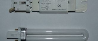
Electronic ballasts belong to the category of modern devices in which the disadvantages of an electromagnetic choke are almost completely eliminated. Schematically, such an element is a single unit that starts the lighting device and supports the combustion process by forming a certain sequence in changing the voltage level.
The advantages of electronic ballast are presented:
- any launch speed;
- no need to install a starter;
- flicker is excluded;
- maximum luminous efficiency;
- compact size and light weight of the device;
- optimal operating conditions.
This is what electronic ballast looks like
Electronic ballasts are an order of magnitude higher than electromagnetic devices, which is due to the complexity of the circuit with the presence of filters that correct the power factor of moments, an inverter and ballast. Some models of electronic devices are complemented by a system of protection against turning on the lighting device without a lamp.
The ease of use of electronic ballasts in energy-saving fluorescent lamps is due to the installation of light sources directly into the base of standard sockets.
Principle of operation
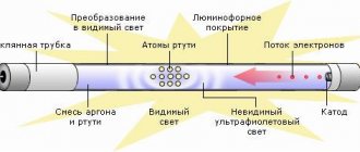
The principle of operation of a fluorescent lamp is equivalent to gas-discharge light sources and is energy-saving. The air is evacuated from the glass flask and an inert gas with a drop of 30 mg of mercury is placed. Spiral electrodes reminiscent of an incandescent filament are built into opposite sides. These electrodes are soldered on both sides to two contact legs placed in dielectric plates. The inside of the tube is coated with a layer of phosphor. The length, diameter and shape of the flask can be different, but the internal structure does not change.
Structure of a fluorescent lamp
The LL is switched on using ballasts - electromagnetic or electronic. Electromagnetic ballasts (EMPRA) include the main element - a choke.
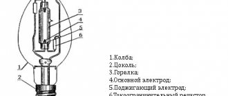
Electromechanical throttle
This is a ballast resistance in the form of an inductor with a metal core, connected in series with the LDS. The choke maintains the uniformity of the discharge and adjusts the current if necessary. The moment the lamp is turned on, the inductor restrains the starting current until the spiral filaments heat up, then produces a peak voltage from self-induction, which lights the lamp.
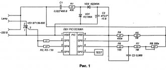
Diagram of a fluorescent lamp with electronic ballasts
Note! The choke restrains the current in the system when turned on, preventing the spiral filaments in the tube from overheating and burning out.
Requirements for ballast resistance:
- minimal power loss;
- small weight and size;
- absence of hum;
- the heating temperature is not higher than 600 degrees Celsius.
Another significant element of the electronic ballast is the glow discharge starter.
Glow starter
When the lamp is turned on, a current discharge occurs in the starter, heating the bimetallic contacts. They close, increasing the current in the lamp circuit, which leads to heating of the electrodes. Next, the bimetallic contact of the starter cools down and opens the circuit. At this moment, the ballast (choke) emits a high-voltage pulse to the electrodes. An arc discharge occurs between them, causing ultraviolet radiation. This causes the phosphor on the surface of the flask to glow in the human-visible spectrum.
A fluorescent lamp with an electromagnetic choke operates in two modes: ignition and glow.
Electronic ballasts (EPG) are used in new generation luminaires, extending the service life of the lamp and increasing efficiency. In the glow mode, the voltage level on the electrodes allows the LL to operate with burnt-out spirals, which is impossible with electronic ballasts. The electronic ballast circuit excludes the use of starters.
Electronic ballast connection diagram
Electronic ballasts are quite expensive and difficult to repair on your own, so electromechanical chokes are widely used.
Electronic ballast
Important! The lamp with electronic ballast operates in four modes: on, preheating, ignition and combustion.
Most common malfunctions
As a rule, sources of malfunction that are associated with the operation of fluorescent lamps are represented by malfunctions in the electrical circuit of the ballast and starter. By assessing the characteristic visual effects, the causes of the malfunction can be reliably determined:
- the presence of a “fiery snake” curling inside the flask is the result of exceeding the permissible current values and instability of the electrical discharge;
- a dark bulb in the area where the output base contacts are located indicates a discrepancy between the current indicators for starting and operation with the current-voltage characteristics;
- Burnout of spirals in fluorescent lamps may result from insulating wear of the winding of the ballast.
Quite often there are problems accompanied by the appearance of a burning smell or third-party sounds. In this case, we can assume the appearance of an interturn short circuit on the induction coil.
Power check
How to check the generator
Measuring the power of a light bulb allows you to create more suitable conditions for it and use it for its intended purpose. You don't need a high-power lamp to read a book or a low-power lamp to do small jobs.
The easiest way to measure is with a multimeter. With its help, measurements will be made quickly and with high accuracy. But if such a device is not at hand, you can use another method, which is also quite effective.
You will need to have a voltmeter and an ammeter. They are connected to the lamp switching circuit, the ammeter in series, and the voltmeter in parallel. Then you should turn on the power supply to the device. Then you take readings from both meters and write them down. Dividing the resulting current strength by the voltage shown by the voltmeter, you will get the value in watts. This indicator will be the rated power of your light bulb.
Testing performance
Functionality testing is a very easy verification process. The first thing to do is, of course, try to connect the lamp to the network directly or install it in an appropriate lamp. After which you can draw conclusions about the serviceability and functioning of the device.
Causes of breakdown and repair
A more detailed check will consist of testing each element separately, but this one will take much more effort and will require you to have certain knowledge in this area.
Causes of breakdowns and their repair
There are many options for malfunctioning fluorescent lamps; we have prepared for you the most common types and methods for solving them.
Having figured out the cause of the problem, you can easily solve it, let's start studying our list:
- The device does not turn on - the cause of such a malfunction may be the loss of functionality of the lamp or breakage of wires, circuits and contacts. It is necessary to replace the lamp; if this does not help, you should look for the cause in the connections and wires; perhaps there is a circuit break somewhere.
- The lamp begins to blink, but does not light up until it glows steadily - This is due to a short circuit in the wires or between the contacts. It is necessary to check the insulation and replace the wires if necessary. If this does not help, the lamp itself may need to be replaced.
- A dim glow on both or one end of the device - this happens due to a violation of the seal of the flask. Such a device must be replaced; it cannot be repaired.
- Darkening of the ends and complete shutdown during operation - the cause of this phenomenon may be a faulty ballast. You should completely replace it and test the device again.
- Cyclic dimming and ignition of the lamp - most often the cause of this malfunction is the starter. It should be replaced, as in the case of a broken ballast.
- Burnout and blackening of the ends during switching on - this happens when the incoming voltage does not correspond to the rated voltage. The ballast resistance cannot withstand the increased load, and the lamp immediately burns out. It could also be due to a faulty ballast. In this case, the ballast is also replaced with a new one.
Today I will talk about one problem that is associated with two things - fluorescent lamps and illuminated switches. Illuminated switches are a truly functional and convenient thing. There is no need to fumble around in a dark corridor looking for a light switch. In this case, a neon lamp or LED is used as an indication element in series with a resistor. When the switch is turned off, the backlight comes on, and this can only mean one thing: current is flowing through the circuit.
How to check a fluorescent lamp choke with a multimeter
The most wear-resistant element in the design of luminaires with fluorescent lamps is the inductor, the breakdown of which is quite rare. A malfunction of such an element can be represented by a break or winding burnout, or violations of interturn insulation in electrical wires.
Both faults can be detected by connecting a tester in the form of a multimeter to the choke terminals to measure resistance. The presence of infinite resistance indicates a break and burnout.
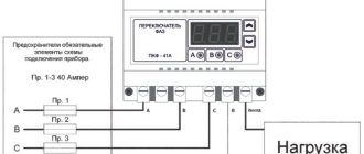
Starter and choke for fluorescent lamps
As a rule, burnout is accompanied by the appearance of an unpleasant odor emanating from the part that has become unusable.
Any verification processes described above are valid only in the case of using electromagnetic ballasts, since electronic ballasts exclude the presence of a starter in the circuit.
How to check a fluorescent lamp starter
The process of checking fluorescent-type lighting devices involves not only monitoring the spiral integrity inside the bulb, but also the performance of the throttle and starter systems.
- capacitors that should not be swollen, deformed or burst under the influence of excess voltage in the electrical network;
- light source bulb, which should not be blackened.
Capacitor integrity is checked using a multimeter in ohmmeter mode with the maximum possible resistance measurement limits.
If the readings on the tester are less than 2.0 MOhm, then it can be assumed that there is an unacceptable current leakage in the capacitor. As practice shows, the best option when carrying out independent repair work is to completely replace all elements that have become unusable (starter and throttle) with new devices of a similar type.
Setting the device to the desired mode for testing
A multimeter (tester) is a compact device that allows you to perform various electrical measurements. It is useful for identifying faults in electrical networks and power tools.
The dialing procedure involves checking the integrity of the electrical circuit and the presence of direct contact. In most tester models, this mode is built-in initially. To activate it, you need to turn the switch in the center of the device to the appropriate position (towards the buzzer or diode icon).
In addition, it is necessary to connect the measuring probes correctly. The black probe should be inserted into the holes marked “COM” and the ground symbol. The red meter must be inserted into the connector marked “VΩmA”. Testing can begin immediately after placing the controls in the required position.
The metal tips must be closed, after which a beeping sound should be heard from the buzzer. The display will show zero values, which means there is no resistance or discontinuity. If the 220 Volt circuit is open, the number “1” will be displayed on the screen.
Purpose and device
In some devices, chokes are installed in order to pass pulse currents of a certain frequency range. This range depends on the design of the inductor, that is, on the wire used in the coil, its cross-section, the number of turns, the presence of a core and the material from which it is made.
Structurally, the inductor is an insulated wire wound around a core. The core can be metal, made up of insulated plates, or ferrite. Sometimes the choke can be made without a core. In this case, a ceramic or plastic frame for the wire is used.
The throttle valve is present in the carburetor. It regulates the supply of the combustible mixture, representing a potentiometer. To check the throttle sensor in a car, determine whether the input voltage of the device corresponds to the throttle position .
In lamps
In luminaires designed for the use of fluorescent lamps, in addition to the lamps themselves, components such as a starter and a choke are used.
The starter, as the name suggests, starts the glow process in the lamp and does not participate further in the process. The choke functions as a current and voltage stabilizer during the entire period of the lamp's glow.
If the choke is faulty, the lamp does not light or does not burn steadily, its glow is not uniform along its entire length, and areas with a brighter glow may appear inside, moving from one electrode of the lamp to another. Sometimes you can notice the flickering effect of the light.
If the throttle is faulty, the lamp may not light up the first time, and the starter will turn on repeatedly until the lighting process finally starts. As a result, dark spots will appear on the lamp bulb where the spirals are installed. This is due to the fact that the coils operate for a longer time than is set for normal starting.
The principle of operation of a fluorescent lamp and its scope
The working ability of a fluorescent lamp lies in the glow of phosphors that react to exposure to ultraviolet rays. The light output of this device is 5 times higher than that of incandescent lamps.
The principle of operation of a fluorescent lamp and its scope
The validity period can be quite long, but this is influenced by a number of important factors, such as maintaining electrical ballast, eliminating voltage surges and short circuits.
Fluorescent lamps are in great demand today and are used at home. This device is quite economical in cost and in further operation. The use of fluorescent lamps in production is not excluded. In this industry, they are very practical and allow you to illuminate the room well at any time of the day. Having looked a little at how a fluorescent lamp works, let’s move on to the issue of recycling this device.
Checking in lamps
The throttle must be checked if one of the above-described phenomena is observed when the fluorescent lamp is operating, as well as if a characteristic smell of burning insulation is noticed, sounds that are not typical for the operation of the device are observed, and also if the lamp does not turn on.
Before checking the lamp choke, the lamp itself and the starter are checked.
A malfunction of the inductor may consist of a break or burnout of the coil wire or an interturn short circuit caused by breakdown or burning of the insulation.
Both malfunctions can occur either due to a long period of use of the device, or as a result of any mechanical impact. It is possible for the coil wire to burn out as a result of supplying it with a current greater than the maximum for which the inductor is designed.
In the event of a wire break or burnout, you can identify the fault with a conventional tester or multimeter. Due to the fact that the inductor passes direct current, closing the tester circuit through the coil, you can understand by the glow of the control lamp or its absence whether there is a break or not.
If, when measured with a multimeter, the resistance is infinite, the coil wire has broken.
Checking throttles
In case the lamp suddenly stops working. First you need to make sure the ballast is working properly. To do this, the inductor is removed from the device body for diagnostics.
Throttle malfunctions
The most common breakdowns that occur are:
- Winding break. This often happens with low-quality coils made of insufficiently purified copper or aluminum;
- Closing the turns. This breakdown is possible if the conductor insulation is made using low-quality varnish;
- Damage to contact terminals. If the contacts are not tightly screwed to the pads, carbon deposits may appear on them, which will prevent the flow of current.
If the design of the luminaire allows, it is recommended to dismantle it entirely for subsequent diagnostics, rather than removing individual faulty elements
Checking throttles
A break is easily determined using a tester. To do this, the probes of the measuring device, included in the circuit continuity test mode, touch the ballast terminals in the mode. An audible signal indicates that the coil is working properly.
Interturn short circuits are more difficult to diagnose. It is necessary to know the inductance of a working coil. This information can be obtained by examining the labels on the ballast, visiting the manufacturer’s website, or measuring this value on a known-good device.
You should also check whether the winding is breaking through the housing, which will also indicate a coil malfunction. To do this, one probe of the tester touches the coil body in the circuit continuity test mode, and the other touches sequentially both contacts of the coil. There should be no sound indication.
Replacement
To replace a failed ballast, it is removed from the lamp. To dismantle it is necessary to remove the decorative panel and reflector. In order not to damage the lamps, it is recommended to remove them too. This should be done carefully so as not to damage the fragile flasks.
The ballast itself is secured with screws in the lamp body. Working near the ceiling is not always convenient. If the design of the luminaire allows, it is recommended to dismantle it entirely for subsequent diagnostics, rather than removing individual faulty elements.
Checking turn-to-turn short circuit
In the case of an interturn short circuit, checking with a tester will not give a result. In this case, you need to know how to check the throttle using a multimeter.
An interturn short circuit occurs when there is direct galvanic contact between two turns or when the turns come into contact with a metal core. Obviously, in this case the coil resistance decreases.
There may be a rare case when measuring the coil resistance will not give a reliable picture of its condition. This can happen when there is a break and an interturn short circuit at the same time.
In this case, the interturn short circuit may turn out to be parallel to the break, and several turns simply will not participate in the measurement. A seemingly serviceable throttle will not work correctly.
To check the coil for the presence of an interturn short circuit, an analog multimeter in milliammeter mode must be used as part of a device assembled with two transistors.
The diagram of the device is shown in the figure.
The device itself is a low frequency generator. When assembling the circuit, any transistors from the MP39-MP42 line are used (gain factor 40-50).
Diodes can be used type D1 or D2 with any index. Resistors are used of any type, designed for a power of at least 0.12 W. The device is powered from a DC source with a voltage of 7-9 V.
Features of diodes
A standard diode is a component of the electrical network and acts as a pn junction semiconductor. Its structure allows current to pass through the circuit in only one direction - from the anode to the cathode (different ends of the part). To do this, you need to apply “+” to the anode and “-” to the cathode. Due to this feature of the product, if you suspect a breakdown, it can be checked with a tester or multimeter.
Various types of diodes.
Today in radio electronics there are several types of diodes: Types of diodes:
- Light-emitting diode. When an electric current passes through such an element, it begins to glow as a result of the transformation of energy into a visible glow;
- protective or regular diode. Such elements in the electrical network act as a suppressor or voltage limiter. One of the varieties of this element is the Schottky diode. It is also called a Schottky barrier diode. Such an element, when connected directly, gives a low voltage drop. In Schottky, instead of a pn junction, a metal-semiconductor junction is used.
It will be interesting Ways to check transistors for performance
Here is a small selection made up of specific diodes and their corresponding Vf values, which were obtained when testing them with a multimeter. All diodes were previously checked for serviceability.
Table of measurements of diode characteristics using a multimeter.
If ordinary parts and LEDs are used in the vast majority of electrical appliances, then Schottky ones are used mainly in high-quality power supplies (for example, for devices such as computers). It is worth noting that testing a conventional diode and a Schottky diode is practically no different, since it is carried out according to the same principle. Therefore, there is no need to worry about this issue, because the operating principle of both Schottky and conventional diodes is identical.
Schottky diode
Being a component of an electronic circuit, such semiconductor elements often fail. The most common reasons for their failure are:
- exceeding the maximum permissible direct current level;
- excess reverse voltage;
- poor quality part;
- violation of the device operating rules established by the manufacturer.
Moreover, regardless of the cause of loss of performance, failure can be directly caused by either a “breakdown” or a short circuit. In any case, if there is an assumption that the electrical network has failed in the semiconductor area, it is necessary to diagnose it using a special device - a multimeter. Only to carry out such manipulations you need to know how to check the diode using it correctly.
What is a multimeter
A multimeter is a universal device that performs a number of functions:
- measures voltage;
- determines resistance;
- checks wires for breaks.
It will be interesting How to make a power regulator on a triac with your own hands
Using this device you can even determine the suitability of the battery.
Checking the LEDs in the lamp.
How to test a diode
After we have figured out the semiconductors of the electrical circuit and the purpose of the device, we can answer the question “how to check the diode for serviceability?” The whole point of checking diodes with a multimeter is their one-way electrical current carrying capacity. If this rule is observed, the electrical circuit element is considered to function correctly and without failures. Conventional diodes and Schottky diodes can be easily tested using this device. To check this semiconductor element with a multimeter, you need to do the following manipulations:
- you need to make sure that your multimeter has a diode test function;
- If such a function is available, we connect the probes of the device to the side of the semiconductor from which the “ringing” will be carried out. If this function is missing, then use the switch to switch the device to 1 kOhm. You should also select the mode for measuring resistance;
- the red wire of the measuring device must be connected to the anode end, and the black wire to the cathode end;
- after this, you need to observe changes in the forward resistance of the semiconductor;
- we draw conclusions about the presence or absence of voltage
The unit can then be switched to check for leaks or high circuits. To do this, you need to change the location of the diode output. In this state, it is also necessary to evaluate the obtained values of the device.
Sequence of action
The verification procedure is as follows:
- The Vk toggle switch turns on. In this case, the multimeter needle should deflect to the middle of the scale;
- depending on the inductance of the coil, the position of the variable resistor R5 is set. The left position corresponds to less, and the right to greater inductance. When checking coils with inductance less than 15 mH, you must additionally press the Kn2 button;
- The inductor terminals are connected to the Lx terminals and contact Kn1 is closed with a button. In this case, if there are no turns in the winding that are short-circuited with each other, the multimeter needle should deviate towards higher values or slightly deviate towards smaller values. If the winding has at least one short circuit between the turns, the arrow returns to zero.
Sometimes the cause of a coil malfunction can be a broken or damaged core. The material from which the core is made, its size and position relative to the coil affect the inductance.
Inductance check
The presence in the arsenal of a multimeter of such a useful function as measuring the inductance of the coils will be useful for checking the compliance of the inductor with the characteristics stated in the reference literature. This feature is only available on some digital multimeter models.
To use this feature, you must set your multimeter to measure inductance. The probe contacts are connected to the coil terminals. For the first measurement, the multimeter is set to its largest measurement range, and then the range is reduced to obtain a measurement of sufficient accuracy.
When carrying out all measurements, it is important not to allow your hands to touch the contacts on which certain parameters are measured, otherwise the conductivity of the human body may change the readings of the device.