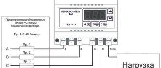
In some cases, industrial and sometimes household single-phase lines are powered from a network with three or four phases. In order to select a phase with a voltage corresponding to the line parameters, an automatic phase switch is installed in the circuit. This device ensures uninterrupted power supply and also protects connected devices from surges that can cause equipment failure. The automatic phase switch is connected to a three-phase or four-phase network, through which electricity is supplied to a single-phase line. One of the phase conductors at its output is connected to the protected circuit. When the voltage parameters on it go beyond the normal limits, the device switches the power supply to power from another cable.
Switch operation order
An automatic switch is a digital device based on microprocessors. The device is durable and highly accurate, allowing for reliable protection of equipment connected to the network.
When connecting the device to the line, any phase conductor can be selected as the supply conductor.
To prevent the contacts of the output relays built into the device from sticking, the device is equipped with an internal lock. In addition, it monitors the state of the contactors of the starters, which are located in the external electrical circuit. Using this device helps prevent phase overload.
Application area
First, it is necessary to talk about the decoding of AVR - automatic input of reserve. These systems are required to be used in the electrical networks of consumers of the first category. They are necessary to ensure that power outages do not lead to serious financial losses or a threat to people's lives.
ATS systems are usually classified according to their operating principle:
- Single-sided - the circuit includes sections of the main and backup power.
- Bilateral - each line can be used as a backup or primary.
- Restoring - after the main power source is restored, the system returns to its previous operating mode.
- Non-recoverable – the backup power system is switched off manually.
ADF installation parameters
The following settings are typical for the models of these devices:
- Limit voltage (upper and lower). The maximum voltage indicator is the most significant, and it is important to choose it correctly without making a mistake when setting it up. If it is too low, the device will constantly operate, and if the selected value is too high, overheating of the internal wiring is inevitable, which can lead to a fire.
- Priority phase of ACE. If there are no voltage drops on it, the device will not switch to other lines. In the event of a power surge, the line power will be switched to another conductor, but at the same time the device will continue to monitor the priority core. When the potential difference across it is normalized, the load will switch back.
- On time. This term refers to the delay period after the voltage disappears on all current-carrying conductors. When it expires, the device will try to turn on the power again.
- Return time. This is the interval after switching the power from the priority core to the backup one, after which the device will check the main phase, and if its parameters are normal, switch the power supply to the line to it. If the priority conductor is not ready to connect the load, the test will be repeated after the same time period.
Features of connection and operation of the device
The automatic switch is installed immediately after the electric meter. The device connected to the line tests the condition of the conductors and connects the circuit to the core whose parameters best correspond to the required ones. During operation, the device constantly monitors the voltage, which should not go beyond the established limits.
Operating procedure and device of the phase switch in the video:
During operation, voltage control is carried out not only on the priority phase, but also on two backup ones. This is necessary so that if the parameters on the main conductor are violated, without delay, select another core to switch the power. If the voltage on both backup lines is within acceptable limits, switching proceeds from L1 to L2 and further (phase designations are on the device body, each has its own LED).
If the potential difference does not correspond to the specified parameters on any conductor, power will not be supplied through them. When the voltage on the priority line normalizes, the connection will be made to it first.
Automatic power supply switch
Automatic power supply switch When powering a device from multiple sources (for example, using a buffer power supply), it is often necessary to use the one that currently has the highest power. A conventional circuit with Schottky diodes introduces small energy losses, especially at high load currents. The presented circuit uses MOSFET-N transistors as switching elements, which minimizes energy loss.
The operation of this automatic power supply switch is based on the fact that it compares two voltage sources in real time and selects the one that has a higher voltage. The selected source is used to power the device connected to the third pair of terminals. The value of this voltage is not important. In other words, it behaves like a diode switch.
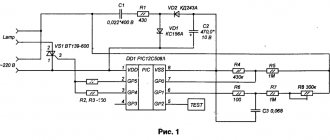
This switch uses N-channel MOSFETs as control elements - they have the lowest open-channel resistance. In addition, the diode between the drain and source is directed so that it does not cause current to leak from the receiver after both power supplies are turned off. Since the positive cable was interrupted, a higher potential than the cable was required to polarize the gates. The circuit diagram of the automatic power supply switch is shown in the figure.
Diodes D1 and D2 protect the transistor's gate, limiting the maximum gate voltage to approximately 13V. This voltage, in turn, is sufficient to completely turn on this transistor. Resistor R1 discharges the gate - the transistor will not turn on accidentally. Resistor R2 limits the current flowing through the zener diodes and the op-amp output to a few milliamps.
Op-amp US1A acts as a comparator for the output voltage (supplied to the sink) connected to the inverting input and the source input, reduced by about 0.1%, connected to the non-inverting input. If the source voltage is higher than that supplied to the receiver, the potential of the non-inverting input will overwhelm the inverting input. The op amp output is high, which polarizes the transistor's gate, turning it on.
Even with zero voltage drop across the transistor, the relationship between the input potentials of the US1A system is still maintained. This is facilitated by a voltage divider consisting of resistors R3 and R4, the task of which is to reduce the input voltage by an amount greater than the voltage offset of the amplifier used - about 5 mV.
The transistor will turn off when the output potential exceeds the input potential. The output will be at about 0V, meaning the gate voltage will become negative. Zener diodes switched in both directions ensure that the transistor is not damaged in this situation. The specified divider R3 + R4 is required when turning off. Their role is to overcome the amplifier's offset so much that the input voltage is still higher than the input voltage.
Without this, the transistor may click in its conducting state. Only with an ideal amplifier, with zero voltage offset, can you dispense with this divider. The supply voltage for the operational amplifier is provided by a simple switching converter. It is powered by a voltage intended for the consumer so as not to be affected by its operation.
The automatic power supply switch was assembled on the MC34063A chip in its normal state, and the output voltage is about 28V. The LM358 chip allows a supply voltage of no more than 32V. The circuit is assembled on a double-sided printed circuit board measuring 45 mm × 55 mm and is shown in the figure.
Transistors must be installed on the radiator. The model uses transistors of the IRL3705N type. A load drawing a current of 2 A caused a voltage drop of 23 mV. In comparison, the SK34 Schottky diode causes a voltage drop of 0.5 V. There is nothing stopping you from using a different type of MOS-FET-N transistor as long as its terminals have the same pinout arrangement as the IRL3705N. The range of permissible input voltages supplied to connectors J1 and J2 is 5 ... 16V. The lower limit is due to the need to ensure normal operating conditions for the converter. The 5...16V range makes the circuit ideal for interfacing with 6 and 12V batteries and devices.
Main types of ACEs
In modern networks in our country, the most common switch models are PF 431 and PF 451. Let us consider them in more detail.
PF 431
This device provides reliable protection of household equipment from voltage surges on phase conductors. It can be installed together with air conditioners, refrigerators and freezers, computers, alarm and video surveillance systems and other equipment that must be continuously supplied with electricity.
The device works according to the following principle. A three-phase voltage is connected to the APF input, and a single-phase network with parameters 220V, 50Hz is connected to the output. The device monitors the output potential difference, and if it goes beyond the established limits, it connects the line to a phase conductor whose parameters correspond to the norm. At the same time, control over the priority conductor, which for this model is L3, does not stop.
When the voltage on it returns to normal, the reverse connection occurs. If the potential difference on L3 is stable, power reconnection to the backup phases will not occur.
PF 451
This device is designed to ensure power stability of single-phase lines. It is used with various household equipment, like the PF 431, and works on a similar principle, which there is no need to describe again. The main difference between them is that the PF 451 does not have a priority phase. Therefore, a line with optimal voltage values is always selected for connection.
Operating principle and installation of an electrical circuit based on a phase switch on video:
Description and purpose of AVR
An electrical panel or ATS cabinet is a device used to start backup power manually or automatically when the voltage drops. If the main power supply equipment fails, this causes loss of power to consumers. Therefore, an energy backup system with auto-start for a generator or switchboard will prevent disruption of the technological process. The ATS circuit can be used to activate additional equipment when the main devices are turned off.
The cabinets and equipment themselves are manufactured for one-way service and are used for installation on objects of the first and second categories. The response time of the automatic transfer system may vary depending on the type of equipment. The device is supplied with voltage; for this, two or three independent sources are used. The equipment must be connected to the network in advance so that the user can carry out control and configuration in advance. Load failures may occur when switching to an additional power supply.
TheMIKLLLE channel spoke about the principle of operation of the automatic reserve system.
Requirements
The following requirements are imposed on reserve input systems:
- Switching on the switchboard at 40 A, 100 A or with other parameters must be performed when there is a load loss in the equipment buses, regardless of the reason. This occurs when the switches of a functioning power source are turned off in an emergency, accidental or arbitrary manner. Also, activation of the ATS equipment should be carried out when there is a loss of voltage in the buses that are powered from the main source, or when a short circuit occurs on the equipment buses.
- The backup equipment is activated immediately when the main power supply is turned off. This will reduce the duration of the interruption in power supply to the shields.
- The operation of the reserve input system should be one-time.
- Activation of the ATS should not be performed until the switch of the operating source is turned off. Thanks to this, parallel operation of several sources will be prevented.
- In modern switchboards, manufacturers provide protection for an additional source after activating the redundancy system.