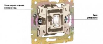
Advantages of capacitive switches
Speaking about the advantages of this type of switches, the following qualities should be noted:
- Long service life. This is greatly facilitated by the absence of moving parts and contact groups.
- Compatible with all types of lighting fixtures. Models with dimming are available for LED strips and energy-saving lamps, if they have such an option. In addition, switching of any circuits that meet the operating conditions of the switches is allowed
- Availability of additional functions.
- Possibility of integration into the Smart Home system.
- Large selection of colors and designs. Switches “Hares” model range Kopou
- No mechanical contacts.
- The touch sensor can be installed in a standard “glass” for a hidden wiring switch.
Now briefly about the shortcomings. First of all, it is necessary to note the difference in cost with conventional mechanical switches, but it has become significantly less than 10-20 years ago. The price of inexpensive Chinese touchscreen models today is much cheaper than mechanical switches from well-known brands, such as GTS or Electronics.
Sometimes LED lamps connected to touch switches flicker. This may be due to both the low quality of the lighting sources themselves and the low-cost switch models. The problem can be resolved in two ways:
- Use products from well-known brands (Jazzway, Panasonic, Sapphire, Funry, LightaLight, Tronic, Sesso, etc.).
- Connect a 0.1 uF 630 V capacitor in parallel with the LED lamp.
An example of the implementation of lighting in a bedroom using Livolo pass-through switches
Task:
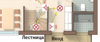
- Implement control of the general lighting of the room from three places. 3 - at the entrance to the bedroom, 1 - the glory of the bed, 2 - to the right of the bed.
- Implement control of sconces on the left of the bed and on the right of the bed.
The connection diagram for Livolo pass-through switches in this case will be as follows:
After connecting the pass-through switches, they must be synchronized to work together. See video example of synchronization above on this page.
Annotation. After connecting and synchronizing, the light control in the room will be like this:
- Lamp No. 3 is controlled from switch No. 1, No. 2, No. 3;
- Lamp No. 1 is controlled from switch No. 1
- Lamp No. 2 is controlled from switch No. 2
Other mounting options
It is necessary to consider a few more features of connecting touch switches. The pass-through switch circuit is used when installing lighting fixtures, for example, in a long corridor.
In this case, it is impossible to open the electrical circuit of the lamp at the beginning and end of the route with one switch. This would cause connection difficulties. To prevent this from happening, pass-through switches are used. They are connected according to a special circuit.
You need to purchase two pass-through switches. Their choice depends on the total power of electrical appliances.
The phase is supplied from the network, supplied first to the first and then to the second touch switch. The neutral wire comes from the opposite side. It passes through the lighting fixtures. From each lamp, a wire is connected to the corresponding terminal of the second switch (1.1 and 1.2). Then another neutral wire comes out of the same device from the “COM” terminal. It is carried out to the same terminal on the first switch. This allows you to connect two touch sensors into a single system.
Advantages of touch switches
The advantages of touch switches include:
- increasing the service life of electricity consumers (due to the possibility of smooth switching on, which eliminates even short-term operation in extreme starting mode),
- long service life,
- reliability,
- compatibility with any lighting devices (incandescent lamps and other types of lamps),
- Possibility of economical operation of consumers and power regulation.
In order for the touch lamp to live up to expectations and significantly increase the comfort of the room, it is important when choosing to take into account all your needs and determine what functions you would like to “entrust” to the device. It will be easier to formulate requirements if you answer the following questions:
- How many light sources are you planning to connect to the touch switch?
- Where are you planning to install the switch (do you need a model that is resistant to temperature changes or )?
- Are there plans to connect additional electrical appliances, and is it necessary to automatically control their operation (presence of a temperature sensor)?
- Do you need a function to automatically turn on the lights when people appear in the room and turn them off when they are absent (motion sensor)?
Legrand
Multi-brand company with a central office in France. In Russia there is not only a representative office of the company, but also a production site, however, in Dubna, where it is located, they produce only small-section cable channels. Touch switches, distinguished by good quality and functionality, are imported from abroad and have a real “imported” price: a single-channel device costs about 3.5 thousand rubles.
Livolo
Domestic products are traditionally competitive in terms of prices, however, their characteristics often leave much to be desired. The products of the Ekaterinburg company Livolo cannot be called of poor quality, however, its touch switches may not work correctly with LEDs (lamps, strips) etc. But the price of a three-channel device is less than that of a single-channel imported device - 2.1-2.3 thousand rubles.
Technologies do not stand still, and now we already have a touch switch in wide use, which allows us to take the lighting control system in the house to a fundamentally new level.
Our article will tell you why such a device is needed, what it is and how it works. Thanks to this, you can make a touch switch with your own hands for 12 or 220 volts without any problems, and the connection itself, both a home-made device and a purchased one, will not be difficult.
Homemade touch switch
Some users believe that the touch switch circuit is relatively simple. Therefore, making such a device with your own hands will not be difficult. To do this you need to know how to use a soldering iron. You will need to purchase the appropriate parts:
- Transistors KT 315 (2 pcs.).
- Electrolytic type capacitor 16 V (100 µF).
- Resistance 30 Ohm.
- A regular capacitor is 0.22 µF.
- Power supply or powerful battery with an output voltage of 9 V.
- Semiconductor D 226.
You need to choose a suitable housing (suitable from an old switch). A hole is made on the front part for connecting wires. The circuit from the listed parts must be soldered in the following sequence.
The assembled structure is connected to the power supply. The wire must be soldered to a metal plate fixed to the front plane of the device.
Device options and capabilities
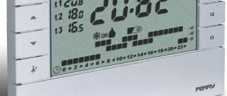
The development of a touch switching product equipped with a timer clearly deserves special consideration. There are traditional characteristics here, such as:
- silent operation;
- interesting design;
- safe use.
In addition to all this, another useful feature is added - a built-in timer. With its help, the user is able to control the switch programmatically. For example, set on and off times in a certain time range.
A unique option for developing a switch with integrated timer functionality. With the help of such devices, it is possible to control lighting at a strictly specified time. Electricity savings are obvious
As a rule, such devices have not only a timer, but also an accessory of another kind - for example, an acoustic sensor.
In this embodiment, the device works as a motion or noise controller. It is enough to raise your voice or clap your palms and the lamps in the apartment will light up with a bright light.
By the way, in case the brightness is too high, there is another functionality - dimmer adjustment. Touch-type switches equipped with a dimmer allow you to control the light intensity.
Modification of touch devices – acoustic switch. It operates according to a slightly different method, but is also a device that supports technologies for using sensors. In this case, the sensor element is a sensitive microphone
True, there is one caveat for such developments. Dimmers, as a rule, do not support the use of fluorescent and LED lamps in luminaires. But eliminating this shortcoming is most likely a matter of time.
Diagrams and tips for connecting a 220 V device with your own hands
Switch on trigger
factory devices have complex, often incomprehensible circuits for the average person
Important The main element of the circuit is the K561TM2 microcircuit, which radio amateurs very often use. This part is a trigger, which will change its state upon receiving a control signal. Therefore, such a phenomenon is best suited to implement the switch option
Therefore, such a phenomenon is best suited to implement the switch option.
The principle of operation of the circuit:
- The plate is touched.
- An electrical signal is received at the input.
- The trigger is switched by a field effect transistor.
- The signal is multiplied and transmitted to open the thyristor.
- The lamp included in the thyristor circuit turns on.
Based on infrared sensor
- relay;
- photodetector;
- IR LED;
- regular LED.
- DD1 – as a signal generator;
- DD2 – as a system counter.
Attention For a certain period of device waiting time, it is necessary to select a detail of the appropriate parameters. separate article
Touch Switch Parts
All resistors are MLT or S2-33 type. Transistor VT1 - KP501 with any letter, or it is possible to use KP7131A9. Zener diode VD1, which has a stabilization voltage of 6...12V, can be replaced with D814A, KS 175A, D808. Oxide capacitor C1 - K50-24, K50-29. Rectifier diodes VD2-VD5 with a reverse voltage of at least 300V are replaceable with diodes D112-16, KD226V. The HL1 incandescent electric lamp is designed for a voltage of 220V. Transistor VT2 can be replaced with KT815B - KT815G, KT940B - KT940G, KT630A - KT630V.
The touch switch is assembled on a printed circuit board and installed in a plastic case of a suitable size. When soldering elements, you need to ensure that the leads of the radio components are short (to reduce the impact of interference).
If there is a need to change the sensitivity of the sensor, this can be done by selecting the required resistance R2. The sensor can be made from any metal with a diameter of at least 3 cm.
This touch-sensitive light switch allows you to turn on and off a lighting source with a power of no more than 60W. At higher power, the thyristor must be placed on the radiator.
S.V. doesn't work - 2 installation errors
In addition to failure of board parts, the device may not work due to a poorly configured sensor or installation errors - lack of grounding in the right places or a grounded sensor.
If the sensor operates without protective glass, then you must:
- remove glass;
- turn off the power;
- install glass;
- turn on the power supply.
Sometimes it helps.
Attention! If you install glass on a sensor that is under voltage, it will stop working normally.
Touch light switch VL-C701R from Livolo with remote control
Choosing the optimal model
The main determining indicator for the full operation of a touch switching device is the characteristics of the electrical network. The required voltage of 220 V is not suitable for all models. There are options with a deviation of 20-30%.
Therefore, when choosing, you should pay attention to the threshold voltage values indicated in the device characteristics. In case of significant deviations, it will be necessary to additionally install a stabilizer, through which the vibrations will be leveled
In order for the purchase of an electronic switch to meet all expectations and the device to significantly increase the level of comfort in the room, when choosing, you should take into account the necessary functionality that the device must have
To determine the appropriate model of a sensor product, it is necessary to take into account the priority capabilities that are necessary:
- The number of groups of light bulbs connected to the regulator - there can be one, two or three.
- Intensity. Some devices are additionally equipped with a dimmer, which changes the current supplied to the light bulbs.
- Built-in timer. In walk-through models, an automatic shutdown timer is installed that operates after a specified time. These devices are mostly used for corridors and staircases.
- Control method. It all depends solely on the preferences of the buyer. There are devices controlled by remote control, touch, sound, etc.
Having decided on the set of necessary functions, you should choose one of the presented manufacturers. The price category of devices is not cheap, therefore, when purchasing a low-cost product, you may encounter a low-quality analogue.
The Belgian brand Basalte is focused on luxury products. The Deseo model is the embodiment of multifunctionality and exquisite design. Almost all products have LED backlighting
The Belgian company Basalte produces high-quality touch control devices. The developments are focused on consumers with the highest demands.
Elite models are distinguished not only by their original design, but also by one of the highest price categories. Nevertheless, the cost is fully compensated by ease of use, the presence of various functions and simple adjustments.
Despite the fact that many buyers are biased towards Chinese products, Livolo was able to prove the quality characteristics of its products
Among the Chinese representatives, the company Livolo is noted. The main advantages of touch switches of this brand are the affordable cost of products and original design solutions for home improvement that can emphasize individuality.
At the same time, the range is not limited to technically simple models. It is also worth noting the constant replenishment of the assortment.
We also recommend reading our other material, where we talked in detail about how to assemble a touch switch yourself.
Models with dimmer and for LED strip
There is a large selection of models of touch switches on sale, the design of which includes a dimmer. This allows you to smoothly change the light intensity in the room. Adjustments can also be made using the control panel. This will allow you to adjust the brightness of the main lighting or LED strip.
The 12V touch switch circuit makes it easy to connect and control the lighting created by the LED strip. Such devices are called “dimmers”. They are also suitable for any lighting fixtures that operate on 12 V. This is a compact and functional device. It can be used to create additional or primary lighting in the following cases:
- Creation of lighting in the entrance and on staircases.
- Equipment for the Smart Home system.
- Creating an effective interior design and indoor zoning.
In most cases, such devices are not designed to operate from a 220 V network. Therefore, such touch switches are not suitable for a regular chandelier or sconce. You need to take this into account when purchasing.
Marking
It is imperative to consider the features of application, installation, and connection diagrams of touch switches before purchasing. Livolo is one of the most famous manufacturers of the equipment presented. This company produces touch sensors of various types. To understand what qualities a switch has, you need to look at its markings.
When studying the circuit diagram of a touch switch from Livolo and other manufacturers, you should consider the decoding of the designation using the example of the VL C702R model presented by the company.
The first two letters of the marking, VL, are the name of the Chinese brand Livolo. Next comes the letter C7, but it could also be C6, C8. This is a device modification. Next you can see the numbers 01, 02 or 03. This is the number of lighting groups that can be connected to this device. Compared to a mechanical switch, these could be devices with one, two or three keys.
In the marking, the last letters indicate additional functions of the device. So, the letter R is lit, indicating that the sensor is controlled using a radio signal. The letter D in the marking indicates the presence of a dimmer function, there is brightness adjustment, and the letter S is a pass-through switch. The presence of the letter T in the marking indicates that the manufacturer has included a timer in the model.
Features of work
Before considering the connection diagram for touch switches, you need to understand the operating principle of this device. Any device of the presented type is a sensor. He reacts even to a slight touch. The human body has a weak electrical charge. Therefore, it can be detected by a sensitive sensor.
The presented device consists of several required components, such as:
- A highly sensitive element that responds to a person approaching or touching the sensor surface.
- A signal amplifier, which is assembled on microcircuits or semiconductors.
- A switching device that includes a load, such as a mini-relay or thyristor.
Experts say that devices whose circuit includes a thyristor are more reliable. This is due to the absence of a contact part. Over time, the latter may oxidize or burn.
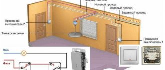
Setting up the control panel
Touch switches look really very stylish - they will look great in the living room, in the hallway, in the kitchen, and anywhere. Another good thing about such devices is that they can be controlled remotely. To do this, you just need to order a universal remote control online. The price of this device, which is a keychain with a carabiner and a metal front panel, is not so high.
There are four buttons on the remote control panel, they are designated in Latin letters - A, B, C, D. This device operates on a 27A battery with a voltage of 12 volts. This remote control is compatible with a variety of touch switches, in particular, with the popular LIVOLO switches of the C6 and C7 series.
Setting up this remote control is quite simple. First of all, you need to press the touch switch button (while it itself must be in the “off” position) and hold it until the “Pi” sound signal is heard from the touch device - this is about 5 seconds.
Then you should press one of the buttons on the remote control (A, B or C), as a result of which another sound signal should be heard - it means that the “binding” procedure is completed. Now the button that we pressed on the remote control during binding can be controlled (disabled, enabled) by touch switches at a distance. All other buttons on the switches are linked to the remote control in exactly the same way.
It is worth noting that several touch devices can be assigned to one button on the remote control. That is, several buttons and even several remote controls can be linked to one sensor. There is information on the Internet that you can make 8 such bindings (I haven’t tried it myself).
| At the same time, button D has a slightly different function than all the others - it is designed to turn off all three lines at once. |
Detaching the sensor from the remote control is also very simple. To do this, touch the sensor and do not release it for about ten seconds
After five seconds the first beep will sound, but this should not be taken into account. And only when another, second beep is heard, all previous settings will be reset
The operating range of the VL-RMT-02 universal control panel is 30 meters. This is quite enough for everyday use - the remote control will properly perform its functions throughout the entire territory of an ordinary apartment.
Connecting a single-key touch switch Livolo VL-C701R
So, let's figure out how to connect a 220 Volt touch light switch. In essence, it is no different from the connection diagram of a single-key switch.
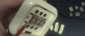
On the switch body there are two terminals marked “L-in” and “L-load”. The “L-in” terminal, the literal abbreviation of which sounds like “live line terminal”. If we use electrical engineering translation, it means approximately the following: “live line” - live line, “terminal” - contact, contact screw. In general, this is a contact for connecting the PHASE wire (the one that came from the distribution box).
The “L-load” terminal in the instruction manual is called “lightin terminal”, translated approximately like this: “lightin” - lighting devices, “load” - load. That is, this is a contact for connecting the wire that goes to the lighting load (the wire that goes to the lamp or chandelier).
As you can see, there is nothing complicated in this “electronic miracle”, everything is like in a regular switch, two terminals “phase-input”, “phase-output”. We strip the wires to the required length and connect them to the terminals.
If you are installing a touch switch to replace the old one, simply unscrew the wires from the old one and connect it to the new one. The main thing is to decide where the phase is and connect it to the desired contact of the touch light switch ("L-in" contact).
The only thing I would recommend is that if you use a cable with a stranded core, use NShVI lugs. The touch switch has screw-type terminals, and if you push a bare stranded wire there when tightening, you can easily crush it.
This is what the Livolo switch looks like from the side
Principle of operation
The touch switch circuit for 12 V and 220 V does not have any special differences when connected. Most often, when the light is turned off, the display will have a blue backlight. If the light is turned on, it will glow red.
The signal from the sensor is fed to the amplifier. Then it goes to the performer relay. Its contacts turn off and turn on the lighting. Control can be done using the remote control. Its range is up to 30 m.
Touch switches have protection that is triggered when the network is disconnected. In this mode, there is a transition to the original off position. The executive relay can withstand loads up to 1 kW. In this case, the load current is 5 A. Such devices are designed to operate from a network of up to 250 V. If voltage surges are observed in the system, it is recommended to install a stabilizer.
Connection diagrams
Instructions for installation and operation of touch switches.
Attention! When installing touch switches, be sure to follow the following instructions:
- Installation should be carried out strictly on de-energized wiring to prevent short circuits and damage to the device.
- Install and remove the glass front panel on a de-energized mechanism.
- Do not recess the support (the metal part of the fastening with screws to the mounting box) into the wall by tightening the screws to maximum force. If it is necessary to loosen the fastening screws by half a turn, the front panel should not rest against the wall on one side and should stand strictly parallel to the wall.
- Supply power to the touch switches only when each line is under load (the output phase is connected to the consumer).
- To avoid contamination of the switch sensor and subsequent incorrect operation, place the front glass panel on the switch immediately after installation. If there is construction dust on the switch sensor, wipe it with a dry, clean cloth and immediately install the front panel.
— During installation, do not allow the metal parts of the installation tool to come into contact with the inner painted side of the front panel.
— Remove the product from the packaging, insert a flat-head screwdriver all the way into the lock located at the bottom of the front panel and turn it axially to disconnect the panel, de-energize the wiring, connect the phase to the L-in input connector, and then connect the out-L1-L2 output connectors ( depending on the number of lines in the product).
— Secure the caliper in the mounting box, connect the upper part of the front panel with the caliper so that the lock teeth fit into the grooves, then bring the lower part of the panel to the caliper and with moderate pressure on the entire plane, lock the lock until it clicks.
Connection diagram for touch switches:
Turning the lighting on and off is done by lightly touching the front panel in the illuminated area where the sensor is located; when it is off it glows blue, when it is on it glows red.
For models with dimming, turning on and off is carried out with a short touch; by adjusting the lighting power with a long touch, the power will increase, and when touched again, it will decrease. The dimmer must only be used with lamps that support dimming. It is acceptable if the dimmer heats up during operation.
Attention! When using LED lamps with a total line load of less than 15 W, the lamps may blink when turned off, in which case you will need an LED adapter
Connection diagram for a touch switch with an LED adapter next to the load:
Connection diagram for a touch switch with an LED adapter in the installation box:
Pass-through touch switches
The pass-through switches must be synchronized; to do this, hold the sensor of one switch until a sound signal, then touch the second, the backlight should blink twice.
Synchronization is reset by holding the touch for 10 seconds or more until a double signal.
Pass-through switches (switches) only work when the phase is connected to the L-in of both products, and the COM-COM connectors are connected.
Connection diagram for single-line pass-through touch switches:
Connection diagram for pass-through touch two-line switches:
Setting up radio controlled switches
To pair, hold your finger on the sensor for more than 5 seconds until you hear a beep. After the beep, press the numbered button on the remote control, repeat for the next lines. To program a scenario button, connect all the necessary lines to one of these remote control buttons according to the algorithm described above. To reset the settings, hold the sensor for more than 10 seconds until you hear a double beep.
How to assemble?
- on reading simple electrical circuits;
- experience with a soldering iron;
- ability to understand electrical and radio components;
- practice in the manufacture of printed circuit boards.
The switch will operate at 9 volts. A rectangular battery is suitable as a power source, but it can be replaced with a battery. When using a step-down transformer or DC-DC converter, you can operate from a 220 W network.
Advice If you do not have the skills or qualifications, it is better not to try to do it yourself. For such people, there is a huge selection of ready-made options.
Parts List
Resistors:
- R1– 10K;
- R2– 1M;
- R3– 22K;
- R5– 2K;
- R6– 1.8K;
- R7– 330 Ohm;
- R8– 1.5K.
Transistors:
- VT1–KT315;
- VT2–RT315;
- V3– 3107 (DC557).
Capacitors:
- C1– 2200 pF;
- C2– 1 µF*10V.
Diode - VD1– 1N.
Miscellaneous:
- M1 - electrical chip;
- HL1 – LED or relay;
- contact block.
Attention: If a relay is used as a load, then resistor R8 must be changed to 2 Ohms
Printed circuit board
Small blank, designed for DIP components. Selecting a case will not take much time. The manufacturing process is not easy, it takes more than one hour. There is enough information on this issue on the Internet. Design is carried out in the Spirint-layout 6.0 program. The manufactured board is shown in photo 1.
Treat the paths with tin. It will protect the surface from oxidation.
An example of the produced coating is in photo 2.