Are you interested in why an electronic ballast module is needed for fluorescent lamps and how it should be connected? Proper installation of energy-saving lamps will extend their service life many times over, right? But you don’t know how to connect electronic ballasts and whether it is necessary to do so?
We will tell you about the purpose of the electronic module and its connection - the article discusses the design features of this device, thanks to which the so-called starter voltage is formed, and the optimal operating mode of the lamps is maintained.
Schematic diagrams for connecting fluorescent light bulbs using an electronic ballast are provided, as well as video recommendations for the use of such devices. Which are an integral part of the gas-discharge lamp circuit, despite the fact that the design of such light sources may differ significantly.
Designs of ballast modules
The designs of industrial and household fluorescent light bulbs are usually equipped with electronic ballast modules. The abbreviation reads quite clearly - electronic ballast.
Old style electromagnetic device
Considering the design of this device from the series of electromagnetic classics, one can immediately note an obvious drawback - the bulkiness of the module.
True, designers have always sought to minimize the overall dimensions of EMP. To some extent this was successful, judging by modern modifications already in the form of electronic ballasts.
A set of functional elements of an electromagnetic ballast. Its components, as you can see, are only two components - a choke (the so-called ballast) and a starter (discharge formation circuit)
The bulkiness of the electromagnetic design is due to the introduction of a large inductor into the circuit - a mandatory element designed to smooth out the mains voltage and act as ballast.
In addition to the choke, the EMP circuit includes starters (one or two). The dependence of the quality of their work and the durability of the lamp is obvious, since a defect in the starter causes a false start, which means an overcurrent on the filaments.
This is what one of the design options for the starter of the ballast control electromagnetic module of fluorescent lamps looks like. There are a lot of other designs where there is a difference in size and body materials
Along with the unreliability of the starter, fluorescent lamps suffer from the strobing effect. It appears in the form of flickering with a certain frequency close to 50 Hz.
Finally, the ballast provides significant energy losses, that is, it generally reduces the efficiency of fluorescent lamps.
Improvement of the design to electronic ballasts
Since the 1990s, fluorescent lamp circuits have increasingly been supplemented with an improved ballast design.
The basis of the modernized module was made up of semiconductor electronic elements. Accordingly, the dimensions of the device have been reduced, and the quality of work is noted at a higher level.
The result of modification of electromagnetic regulators is electronic semiconductor devices for starting and adjusting the glow of fluorescent lamps. From a technical point of view, they have higher performance indicators
The introduction of semiconductor electronic ballasts led to the almost complete elimination of the shortcomings that were present in the circuits of devices of outdated format.
Electronic modules show high-quality stable operation and increase the durability of fluorescent lamps.
Higher efficiency, smooth dimming, increased power factor - all these are the advantageous characteristics of new electronic ballast modules.
Troubleshooting problems opening GHF files
Common problems opening GHF files
TestLink SE309 binary data file not installed
Electronic ballast for fluorescent lamps (EPRA), unlike empra
By double-clicking the GHF file, you may see a system dialog box that says “This file type cannot be opened.” In this case, it is usually due to the fact that TestLink SE309 binary data file for %%os%% is not installed on your computer. Since your operating system doesn't know what to do with this file, you won't be able to open it by double-clicking on it.
Tip: If you know of another program that can open the GHF file, you can try opening the file by selecting that application from the list of possible programs.
Incorrect version of TestLink SE309 binary data file installed
In some cases, you may have a newer (or older) version of the RS232 Interactive Software file that is not supported by the installed version of the application. If you do not have the correct version of the TestLink SE309 binary data file software (or any of the other programs listed above), you may need to download a different version of the software or one of the other application software listed above. This problem most often occurs when you are running an older version of an application with a file created in a newer version that the older version cannot recognize.
Tip: You can sometimes get a general idea of the version of a GHF file by right-clicking the file and then selecting Properties (Windows) or Get Info (Mac OSX).
Summary: In any case, most problems that occur while opening GHF files are due to not having the correct application software installed on your computer.
Even if you already have TestLink SE309 binary data file or other GHF-related software installed on your computer, you may still encounter problems while opening RS232 Interactive Software files. If you are still having problems opening GHF files, there may be other issues preventing the files from opening. Such problems include (presented in order from most to least common):
What does the device consist of?
The main components of the electronic module circuit are:
- rectifier device;
- electromagnetic radiation filter;
- power factor corrector;
- voltage smoothing filter;
- inverter circuit;
- throttle element.
The circuit design provides for one of two variations - bridge or half-bridge. Designs that use a bridge circuit typically support high-power lamps.
Ballast control modules made according to a bridge circuit are designed for approximately such light devices (with a power of 100 watts or more). Which, in addition to power support, has a positive effect on the characteristics of the supply voltage
Meanwhile, mainly modules built on the basis of a half-bridge circuit are used as part of fluorescent lamps.
Such devices are more common on the market compared to pavement ones, since for traditional use, lamps with a power of up to 50 W are sufficient.
Features of the device
Conventionally, the functioning of electronics can be divided into three operating stages. First of all, the function of preheating the filaments is turned on, which is an important point in terms of the durability of gas light fixtures.
This function is seen as especially necessary in low-temperature environments.
View of the working electronic board of one of the models of a ballast module based on semiconductor elements. This small, lightweight board completely replaces the functionality of a massive inductor and adds a number of improved features.
Then the module circuitry starts the function of generating a high-voltage impedance pulse - a voltage level of about 1.5 kV.
The presence of a voltage of this magnitude between the electrodes is inevitably accompanied by a breakdown of the gaseous medium of the fluorescent lamp cylinder - the ignition of the lamp.
Finally, the third stage of the module circuit is connected, the main function of which is to create a stabilized gas combustion voltage inside the cylinder.
The voltage level in this case is relatively low, which ensures low energy consumption.
Schematic diagram of the ballast
As already noted, a frequently used design is an electronic ballast module assembled using a push-pull half-bridge circuit.
Schematic diagram of a half-bridge device for starting and adjusting the parameters of fluorescent lamps. However, this is far from the only circuit solution that is used for the manufacture of electronic ballasts
This scheme works in the following sequence:
- The mains voltage of 220V is supplied to the diode bridge and filter.
- A constant voltage of 300-310V is generated at the filter output.
- The inverter module increases the voltage frequency.
- From the inverter, the voltage passes to a symmetrical transformer.
- At the transformer, due to the control keys, the necessary operating potential for the fluorescent lamp is formed.
Control keys installed in the circuit of two sections of the primary and on the secondary winding regulate the required power.
Therefore, the secondary winding generates its own potential for each stage of lamp operation. For example, when heating the filaments one, in the current operating mode the other.
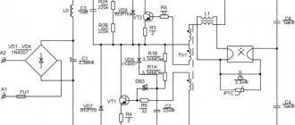
Let's consider the schematic diagram of a half-bridge electronic ballast for lamps with a power of up to 30 W. Here the mains voltage is rectified by an assembly of four diodes.
The rectified voltage from the diode bridge goes to the capacitor, where it is smoothed in amplitude and filtered from harmonics.
The quality of circuit operation is influenced by the correct selection of electronic elements. Normal operation is characterized by the current parameter at the positive terminal of capacitor C1. The duration of the lamp ignition pulse is determined by capacitor C4
Next, through the inverting part of the circuit, assembled on two key transistors (half-bridge), the voltage coming from the network with a frequency of 50 Hz is converted into a potential with a higher frequency - from 20 kHz.
It is already supplied to the terminals of the fluorescent lamp to ensure operating mode.
A bridge circuit operates on approximately the same principle. The only difference is that it uses not two inverters, but four key transistors. Accordingly, the scheme becomes somewhat more complicated, additional elements are added.
An inverter circuit assembly assembled using a bridge circuit. Here, not two, but four key transistors are involved in the operation of the node. Moreover, preference is often given to semiconductor elements of the field structure. In the diagram: VT1...VT4 - transistors; Tp—current transformer; Up, Un - converters
Meanwhile, it is the bridge version of the assembly that ensures the connection of a large number of lamps (more than two) on one ballast. As a rule, devices assembled using a bridge circuit are designed for load power of 100 W and above.
Comparison
Electronic ballasts very quickly bring the lamp into working condition. To do this, she only needs half a second and there is an even stream of light, eliminating flickering. The operating frequency of this electronic mechanism is about 50,000 thousand hertz. This is an important indicator, since the electronic ballast produces only 50 hertz. Of course, a human being cannot catch in 1 second the flickering of light, emitted at a frequency of 50 pulses, but if you stay in a room that is illuminated in this way for a long time, the eye will quickly get tired. The light transmitted by electronic ballasts is perceived by the human eye as close to natural. In addition, lamps equipped with electronic ballasts last approximately twice as long.
Users of lighting fixtures equipped with electronic equipment note that they are also easy to use. To continue their functioning, it is enough only to replace burnt out bulbs. With the electromagnetic type, as a rule, both starters and chokes fail. In addition, if a lamp burns out in an electromagnetic type, electricity continues to flow to the burnt-out lamp. This is dangerous and does not at all guarantee that the installer will not receive an electrical discharge when replacing the lamp. Energy consumption will accordingly continue.
In a similar situation with electronic ballasts, the device will automatically block the energy flow to the burnt-out light bulb, and energy consumption will be reduced by up to 25%.
Differing from EmPR, the electronic type is capable of powering from a constant current source, in other words, from a battery, which is why it is often used for emergency lighting.
Electronic ballasts are also differentiated into two types - cold and warm start. The principle of current supply in them is different. The warm start electronic ballast first gives a signal to the lamp coils, which begin to heat up. Having reached the required temperature, they immediately light up. This entire process takes only a fraction of a second. At the same time, warm start electronic ballasts last 3-4 times longer than their cold start counterparts.
Lamps equipped with electronic ballasts are also completely silent during operation. In this way, they are also more convenient than electronic ballasts, which, especially over time, emit a background hum that causes auditory discomfort to those in the room.
Connection options for fluorescent lamps
Depending on the circuit solutions used in the design of ballasts, connection options can be very different.
If one device model supports, for example, connecting one lamp, another model can support the simultaneous operation of four lamps.
The simplest option for powering a lamp through an electromagnetic ballast element: 1 – filament; 2 – starter; 3 – glass flask; 4 – throttle; L – phase power line; N – zero line
The simplest connection seems to be the option with an electromagnetic device, where the main elements of the circuit are only the throttle and starter.
Here, from the network interface, the phase line is connected to one of the two inductor terminals, and the neutral wire is connected to one terminal of the fluorescent lamp.
The phase smoothed at the inductor is diverted from its second terminal and connected to the second (opposite) terminal.
The remaining two lamp terminals that remain free are connected to the starter socket. This, in fact, is the entire circuit, which was used everywhere before the advent of electronic semiconductor models of electronic ballasts.
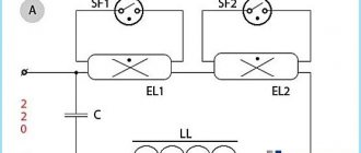
Option for connecting two fluorescent lamps through one choke: 1 – filter capacitor; 2 – choke, power equal to the power of two light devices; 3, 4 – lamps; 5,6 – starting starters; L – phase power line; N – zero line
Based on the same schematics, a solution is implemented with the connection of two fluorescent lamps, one choke and two starters. True, in this case it is necessary to select a choke based on power, based on the total power of gas lamps.
The throttle circuit option can be modified to eliminate the gating defect. It quite often occurs on lamps with electromagnetic electronic ballasts.
The modification is accompanied by the addition of a diode bridge to the circuit, which is switched on after the inductor.
Electronic ballast circuits
It hardly makes sense to assemble electronic ballast with your own hands. Even quality models don't cost enough to justify the time required to assemble them. Unless you want to do something yourself. A self-made thing that works certainly brings moral satisfaction. There are a lot of schemes on the Internet, but many of them are completely unworkable. At this point we will present the workers - based on microcircuits or without them.
Electronic ballast circuit for fluorescent lamps based on transistor switches
Electronic ballasts based on the IR2520D chip from IR with an operating frequency range from 35 kHz to 80 kHz
Electronic ballast circuit based on the UBA2021 chip from NXP. Operating frequency 39 kHz
Ballast with ICB1FL02G chip and 40 kHz frequency
Connection to electronic modules
The connection options for fluorescent lamps on electronic modules are somewhat different. Each electronic ballast has input terminals for supplying mains voltage and output terminals for load.
Depending on the electronic ballast configuration, one or more lamps are connected. As a rule, on the body of a device of any power, designed to connect the corresponding number of lamps, there is a circuit diagram for switching on.
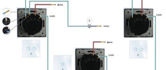
The procedure for connecting fluorescent lamps to a starting and control device operating on semiconductor elements: 1 – interface for network and grounding; 2 – interface for lamps; 3.4 - lamps; L – phase power line; N – zero line; 1…6 — interface contacts
The diagram above, for example, provides for powering a maximum of two fluorescent lamps, since the diagram uses a two-lamp ballast model.
The two interfaces of the device are designed as follows: one for connecting the mains voltage and ground wire, the second for connecting lamps. This option is also one of a series of simple solutions.
A similar device, but designed to work with four lamps, is distinguished by the presence of an increased number of terminals on the load connection interface. The network interface and ground connection line remain unchanged.
Connection wiring according to the four-lamp version. An electronic semiconductor electronic ballast is also used as a triggering and control device. In diagram 1...10 - contacts of the start-up and control device interface
However, along with simple devices - one-, two-, four-lamp - there are ballast structures, the schematics of which provide for the use of the function of adjusting the glow of fluorescent lamps using.
These are the so-called controlled models of regulators. We recommend that you familiarize yourself in more detail with the operating principle of the lighting power regulator.
How do such devices differ from the devices already discussed? The fact that, in addition to the network and load ones, they are also equipped with an interface for connecting control voltage, the level of which is usually 1-10 volts DC.
Four-lamp configuration with the ability to smoothly adjust the brightness: 1 – mode switch; 2 – control voltage supply contacts; 3 – grounding contact; 4, 5, 6, 7 – fluorescent lamps; L – phase power line; N – zero line; 1…20—starter and control device interface contacts
Thus, the variety of configurations of electronic ballast modules allows you to organize lighting systems of different levels. This refers not only to the level of power and area coverage, but also to the level of control.
Cost indicators
Cost indicators for electronic ballasts may be underestimated if the reliability, functionality and strength properties of materials decrease. Consequences:
- reduced service life, half the normal service life of similar parts;
- each start further reduces the specified service time;
- There may be no function for automatically adjusting output powers during network voltage fluctuations. While standard models are conditioned in operating voltage fluctuations up to 200 to 250 watts with a uniform luminous flux;
- Some models do not have automatic power off;
- Some electronic ballasts with a reduced price can only be supplied with alternating current.
Conclusions and useful video on the topic
The video material, based on the practice of an electrician, tells and shows which of the two devices should be recognized by the end user as better and more practical.
This story once again confirms that simple solutions look reliable and durable:
Meanwhile, electronic ballasts continue to be improved. New models of such devices periodically appear on the market. Electronic designs are also not without drawbacks, but compared to electromagnetic options, they clearly show better technical and operational qualities.
Do you understand the principles of operation and connection diagrams of electronic ballasts and want to supplement the above material with personal observations? Or would you like to share useful recommendations on the nuances of repairing, replacing or choosing a ballast? Please write your comments on this entry in the block below.
Make it yourself
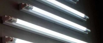
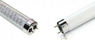
Tubular luminaires with a length of 1200 mm are inexpensive and can illuminate large areas. The lamp can be made with your own hands, for example, from 2 lamps of 36 W each.
- The body is a rectangular base made of non-combustible material. You can use a used lamp that no longer requires repair.
- Electronic ballasts are selected according to the power of the lamps.
- For each lamp you will need 2 G13 sockets, stranded wire and fasteners.
- Lamp sockets are attached to the body after selecting the distance between them.
- Electronic ballasts are installed in the zone of minimal heating from the lamps (usually closer to the center) and connected to the sockets. Each unit is produced with a connection diagram on the case.
- The lamp is mounted on the wall or ceiling with a connection to a 220 V power supply via a switch.
- It is advisable to use a transparent cap to protect the lamps.
Homemade lamp
How does a housekeeper work?
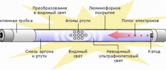
The appearance of fluorescent lamps may vary. Despite this, they have the same operating principle, which is implemented thanks to the following elements that the device circuit usually contains:
- electrodes;
- phosphor - a special luminescent coating;
- glass flask with an inert gas and mercury vapor inside.
The structure of a fluorescent light bulb
This fluorescent lamp is a gas-discharge device with a sealed glass bulb. The gas mixture inside the flask is selected in such a way as to reduce the energy costs required to support the ionization process.
To do this, a voltage of a specific value is applied to the electrodes of the fluorescent lamp. They are located on opposite sides of the glass flask. Each electrode has two contacts that connect to a current source. In this way, the space near the electrodes is heated. The actual connection diagram for this light source consists of a series of sequential actions:
- heating of electrodes;
- then a high-voltage pulse is supplied to them;
- the optimal voltage is maintained in the electrical circuit to create a glow discharge.
As a result, an ultraviolet invisible glow is formed in the flask, which, passing through the phosphor, becomes visible to the human eye. To maintain the voltage to create a glow discharge, the operating diagram of fluorescent lamps involves connecting the following devices:
throttle. It acts as a ballast and is designed to limit the current flowing through the device to an optimal level;
Choke for fluorescent light bulbs
starter. It is designed to protect the fluorescent lamp from overheating. At the same time, it regulates the intensity of the electrodes.
Very often, the cause of breakdown of the housekeepers is the failure of the electronic ballast filling or the burnout of the starter. To avoid this, you can avoid using burnt-out parts in the connection.
Standard connection diagram
The standard circuit used for connecting fluorescent lamps can be modified (go without a choke). This will minimize the risk of failure of the lighting fixture.
Switching option without ballast
As we found out, ballast plays an important role in the design of a fluorescent lamp. At the same time, today there is a scheme in which it is possible to avoid the inclusion of this element, which very often fails. You can avoid turning on both the ballast and the starter.
As you can see, this circuit does not contain a filament. In this case, the lamps/tubes will be powered through a diode bridge, which will create an increased DC voltage. But in such a situation, it is necessary to remember that with this method of power supply, the lighting product may darken on one side. In implementation, the above scheme is quite simple. It can be implemented using old components. For this type of connection you can use the following elements:
- 18 W tube/light source;
- GBU 408 assembly. It will act as a diode bridge;
capacitors with an operating voltage not exceeding 1000 V, having a capacity of 2 and 3 nF.
It must be remembered that the selection of diodes for the diode bridge, as well as capacitors, must be carried out with a voltage reserve. A lighting device assembled in this way will produce a glow slightly less bright than when using the standard connection option using a choke and starter.
Why does the lamp need ballasts?
As you know, all light sources used are divided into two groups: thermal and gas-discharge. Heat lamps are the well-known incandescent lamps. The principle of their operation is based on heating a metal spiral when an electric current passes through it. They connect directly to the network and do not require the use of special devices to run. Incandescent lamps are simply screwed into a socket through which a current of 220 W flows.
Gas-discharge light sources, on the contrary, cannot be connected directly to the network, but require the use of special devices for their operation. This is due to the physics of gas discharge. Thus, in gas-discharge light sources, as the current increases, the voltage across it does not increase, but decreases, unlike other receivers of electrical energy, where as the voltage supplied to them increases, the current flowing through them also increases.
This means that if the discharge current in gas-discharge lamps is not limited, it will grow like an avalanche until one of the three links in the electrical circuit fails: the energy source, the receiver, or the wires connecting the energy source and receiver.
From all of the above it follows that turning on gas-discharge light sources is possible only in conjunction with such devices that, on the one hand, provide a voltage supply sufficient to cause a discharge (i.e., to ignite the lamp), and, on the other hand, limit the current to level required for normal lamp operation. Such devices are called ballasts (ballasts).