One of the main elements of a large number of lighting devices is a ballast, denoted by the abbreviation electronic ballast. The component has features that are best known before connecting to the luminaire. Let's consider the electronic ballast circuit.
The main function of electronic ballasts is to convert alternating current into direct current. In another way, electronic ballast for gas-discharge lamps is also called a high-frequency inverter. One of the advantages of such devices is their compactness and, accordingly, low weight, which further simplifies the operation of fluorescent light sources. And the electronic ballast does not create noise during operation.
An electronic ballast, after connecting to a power source, provides current rectification and heating of the electrodes. In order for the fluorescent lamp to light up, a certain voltage is applied. The current is adjusted automatically, which is implemented using a special regulator.
Electronic ballasts for fluorescent lamps are divided into groups that differ in functionality: analog; digital; standard.
Expert opinion
Viktor Pavlovich Strebizh, lighting and electrical expert
Any questions ask me, I will help!
Some believe that due to the poor quality of electricity supplied in Russia, electronic ballasts too often fail, so chokes are preferred to them. If there is something you don’t understand, write to me!
What is electronic ballast and what is it for?
The use of electronic starting and control equipment or apparatus (abbreviated electronic ballasts) provides a significant increase in the useful life of lighting equipment of this type.
Electronic ballasts are the next round of development of lamp ignition systems. The electronic ballast is produced as a separate module with contacts for supplying power supply and contacts for connecting one or more lamps. This unit replaced a simple but outdated circuit with a throttle and starter. All modern lamps are usually equipped with this design.
What's happened
Electronic ballast uses solid-state electronic circuitry to provide proper starting and operating electrical conditions to power HID light bulbs. They are often based on an SMPS topology, first rectifying the input power and then chopping it at a high frequency. Advanced EBs may allow brightness to be adjusted using pulse width modulation or by changing the frequency to a higher value. Ballasts incorporating a microcontroller or digital circuits can offer remote control and monitoring over networks or simple analog control using a 0-10 VDC dimming signal.
The use of electronic ballasts for HID lighting is becoming increasingly popular. Most new generation EBs can operate with both high pressure sodium (HPS) lamps and metal halide devices, reducing the costs of lighting systems that use both types of lamps. Initially the ballast acts as an arc starter by providing a high voltage pulse and then it functions as a limiter/regulator of the electrical flow within the circuit. EBs operate much cooler and easier than their magnetic counterparts.
Electronic ballast device
An electronic ballast is a complex electronic device. Includes:
- Interference filter: necessary to level out the influence of interference from and into the electrical network;
- Rectifier: needed to convert AC to DC;
- Optional: power corrector;
- Anti-aliasing filter: used to reduce ripple;
- Inverter: increases the voltage to the required level;
- Ballast: analogue of an electromagnetic choke.
In some models, the inverter can be supplemented with a brightness control. To do this, you need an external dimmer (either manual or automatic based on a photoresistor). A lot of schemes have been developed. The element base of electronic ballasts for daytime fluorescent lamps is very diverse: from powerful field-effect transistors in a bridge circuit with loads of hundreds of watts, to driver microcircuits in low-power lamps. But nevertheless, the operating algorithm is the same.
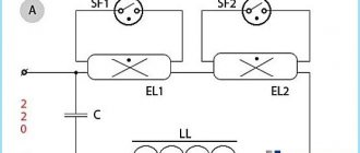
In a simplified form for one fluorescent lamp, the diagram looks like this:
Those. the circuit consists of only two components: a fluorescent lamp and an electronic starter. From an electrician's point of view, this is much simpler than the classic lamp circuit using an electromagnetic choke and starter. Terminals N and L are supplied with mains voltage. Ground pin – grounding. For electronic ballasts to operate, connecting a grounding contact is not mandatory and serves only for safe operation.
The connection diagram for two lamps is similar.
There are no additional elements in it; the circuit is supplemented only by a second lamp, the terminals of which are connected directly to the electronic unit.
Electronic ballast circuits are complex and consist of many electronic components. It is very difficult for a person without an engineering education to understand the diagram. In addition, not every electrician will be able to understand the internal structure.
One of the options for the electronic ballast circuit diagram
This is a fairly simple circuit for an electronics engineer. In a simplified sense, the scheme works as follows. Rectification is carried out by a full-wave rectifier - a diode bridge. Ripple smoothing is performed by an electrolytic capacitor designed for a voltage higher than the mains voltage, since the amplitude value of the sinusoid for the alternating current mains is approximately one and a half times higher than the mains voltage (√2*220V). The remaining processes are controlled by the microcircuit. Field-effect transistors are responsible for supplying voltage to the lamps. Then the converter operates autonomously, the frequency does not change.
Knowledge of electronics allows you to create a power supply circuit for a fluorescent lamp from low-voltage sources. The scheme turns out to be quite compact. The most important thing is to wind the transformer correctly.
Schematic diagram of powering a fluorescent lamp from a low-voltage source
Main varieties
Today there are two types of ballast - electromagnetic and electronic. They differ in how they work, so it’s worth getting to know each of them.
Electromagnetic ballast
This type of implementation involves connecting the inductor in series to the lamp. Also, for the operation of electromagnetic ballasts, a starter is required, with the help of which the ignition process of the lamp is regulated. This part is a gas-discharge lamp, inside the bulb of which there are bimetallic electrodes.
The device works as follows:
- When voltage is applied to the starter, the bimetallic electrodes close due to heat. This leads to an increase in current strength, since it can only be limited by the internal resistance of the inductor windings.
- As the electric current increases, the electrodes of the fluorescent lamp begin to heat up.
- When the starter cools down, the bimetallic electrodes open.
- When the circuit is broken by the starter, a high voltage pulse occurs in the throttle coil, which leads to the ignition of the lighting device.
When the luminescent device returns to normal operation, the voltage on it and the starter is 50% less than the mains voltage, and this is not enough to trigger the second element. As a result, the starter goes into a disabled state and ceases to influence the operation of the lighting device.
Electromagnetic ballast is characterized by low cost and simple design. For a long time, these devices were actively used in the manufacture of lamps, but they have a number of disadvantages:
- It takes about 3 seconds for the luminescent device to enter operating mode.
- Lighting devices with electromagnetic ballast flicker during operation, which negatively affects the organs of vision.
- The energy consumption of these devices is significantly higher compared to electronic ballast.
- The throttle is noisy during operation.
Electronic implementation
Electronic devices are voltage converters that provide power to fluorescent lamps. Although many variations of electronic ballast have been created, most use a single block diagram. At the same time, manufacturers can make certain changes to it, for example, adding a brightness control circuit for a lighting fixture.
Transferring a fluorescent lamp lamp to normal operation using electronic ballasts is most often carried out in one of two ways:
- Before the ignition voltage is applied to the cathodes of the lamp, they are preheated. This allows you to get rid of flicker and also increase the efficiency of the lighting device.
- An oscillatory circuit is installed in the design of the lamp, which enters into resonance before a discharge appears in the lamp bulb.
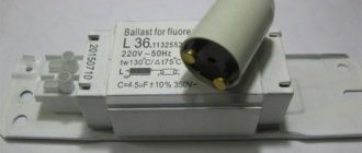
Scheme of ballast for 36w lamps.
Operating principle of the starter
Whatever circuit is used to start a fluorescent lamp. The general operating principle remains unchanged. In principle, similar processes occur when using a throttle and starter. There are only three phases:
- Initial heating of the electrodes. In electronic ballasts this occurs by a fairly gentle increase in voltage on the tungsten filaments.
- Arson. At this moment, the circuit delivers a high-voltage pulse (usually about one and a half kilovolts). This is enough for electrical breakdown of gas and mercury vapor. The ignition voltage of fluorescent lamps is significantly higher than the combustion voltage.
- Combustion. After a high-voltage pulse, the circuit reduces the voltage to that required to maintain the glow discharge. The AC frequency at the electrodes can reach 38 kHz depending on the circuit.
In electronic ballasts, the igniting impulse is provided by an electronic circuit. In the classical scheme - due to the energy accumulated by the inductor. Warming up of the electrodes is also provided by electronic ballasts. With a starter switching circuit, the electrodes warm up at the moment the starter contacts close. It can be replaced with a push button.
How to test a throttle with and without a multimeter. All causes of malfunction of ballasts and electronic ballasts.
Fluorescent lamps, despite the popularization of LED lighting, still remain one of the most common types of lighting devices in homes, garages and industrial premises.
When such a lamp stops burning, the first thing to blame is the light bulb itself or the starter. And if they are not to blame, how to check another equally important element - the throttle?
First, let’s define what a throttle is or what it is also called ballast. In essence, this is an ordinary inductor with a ferromagnetic core.
This is what it looks like in cross section.
In circuits, ballast is needed for three functions:
- current control so that it does not exceed the nominal
- formation due to inductance of a short-term pulse of increased voltage
- smoothing out possible ripples in the 220V network
It is connected in series, and a starter is mounted in parallel with it.
A starter is needed to ignite the lamp.
The voltage supplied to the spiral electrodes at the ends of the lamp is initially insufficient to ignite it. And here the throttle and starter come to the rescue.
After voltage appears in the starter, a discharge is formed inside, which heats the bimetallic electrode.
Due to heating, the shape of the electrode changes and it shorts out.
As a result, the current increases sharply and the electrodes become hot. The current is limited only by the resistance of the inductor itself.
The contacts of the starter gradually cool down and open. When opened, thanks to the choke, a self-induction effect occurs in the lamp, with the formation of a high-voltage pulse and an electrical discharge with a voltage of up to 1000V.
This discharge creates an ultraviolet glow from the mercury vapor that fills the flask. It affects the phosphor, and only thanks to it we can distinguish light in the spectrum that is familiar to us.
If this explanation is too abstruse for some, then here is one of the simplest and most understandable videos that explains in a language understandable to everyone how an LDS lamp works.
It turns out that the process of turning on a fluorescent fluorescent lamp itself is quite lengthy and takes 5 stages:
- supplying 220V from the socket and closing the starter contacts
- supply of a high-voltage pulse from the inductor
- formation of a glow discharge in the flask and supporting it with an external voltage of 220V + bypassing the starter and excluding it from the circuit
As can be seen from the startup process, if the lamps malfunction, three elements may be to blame:
In this case, most often the light bulbs and starter are damaged - due to burnt out tungsten filaments and capacitors.
The easiest way to find out about this is by replacing the starter or light bulb. Moreover, they cost pennies. But how can you quickly find out about a throttle malfunction?
Without special measuring instruments, a faulty ballast may be indicated by the fire snake effect. You can visually observe it inside the lamp.
What does this mean? And this means, first of all, that there is an excess of the maximum permissible current. Because of this, the charge lost stability.
The lamp may also glow intermittently or flicker. If the ballast breaks down, the lamp will not light up the first time.
As a result, the starter will constantly start and stop, start and stop. From such frequent starts, blackening appears near the spirals at the ends of the lamp.
Another way to check without measuring instruments and a multimeter is with a test light. Its power should be approximately the same as the power of the throttle itself.
Connect it in series according to the following diagram with the ballast and watch how it lights up.
- if it doesn’t light up at all, there is a break in the ballast, the throttle is faulty
- burns brightly - there is an interturn short circuit in the ballast
- blinks or lights up at half intensity - the throttle is working
But to be sure that the throttle is damaged, it is still better to use a multimeter and take measurements.
Throttle damage can be of five types:
- short circuit of turns in one winding
One of the wires with which the inductor is wound may simply break. This is easy to detect.
Switch the multimeter to resistance measurement mode and touch the inductor terminals with the probes. If the reading “infinity” is displayed, this indicates a break.
Connection diagrams
The development of such devices was carried out to minimize the design of the lamp and replace the large inductor and starter with one single module, which is connected to the AC power supply and to the electrodes of the fluorescent lamp.
Electronic ballasts are devoid of all the disadvantages of classical connection schemes.
There are modules designed to simultaneously connect four lamps.
Connecting electronic ballasts to four lamps
As is the case with one or two lamps, the circuit does not require any additional elements. The electronic ballast module is connected directly to the fluorescent lamp.
Connection diagram for electronic ballasts with one lamp
Connection diagram for electronic ballasts 4x18 W (Example: Navigator NB-ETL-418-EA3)
Source: vamfaza.ru
Make it yourself
Tubular luminaires with a length of 1200 mm are inexpensive and can illuminate large areas. The lamp can be made with your own hands, for example, from 2 lamps of 36 W each.
- The body is a rectangular base made of non-combustible material. You can use a used lamp that no longer requires repair.
- Electronic ballasts are selected according to the power of the lamps.
- For each lamp you will need 2 G13 sockets, stranded wire and fasteners.
- Lamp sockets are attached to the body after selecting the distance between them.
- Electronic ballasts are installed in the zone of minimal heating from the lamps (usually closer to the center) and connected to the sockets. Each unit is produced with a connection diagram on the case.
- The lamp is mounted on the wall or ceiling with a connection to a 220 V power supply via a switch.
- It is advisable to use a transparent cap to protect the lamps.
Checking the serviceability of the fluorescent lamp and its elements
Lamps of this type (LDS) belong to the class of fluorescent devices used for lighting. They have a number of advantages compared to incandescent lamps. At the same time, the lamp itself is only an integral part of the lighting device, is used as an emitter and works as part of a circuit together with ballasts. The device is far from trouble-free in terms of malfunctions that arise during its operation. To troubleshoot problems that arise, you need to be able to check a fluorescent lamp with a tester.
Schematic diagram
This is a large part of this electronic ballast; the Chinese did not include the inductor and capacitor here.
Actually, a diagram faithfully copied from a printed circuit board. The rating of the electronic components that made it possible to do this was determined not only “by appearance,” but also using measurements, with preliminary desoldering of the components from the board. In the diagram, the resistor values are indicated in accordance with the color coding. Only with regard to the choke, I allowed myself not to unwind the existing one to determine the number of turns, but measured the resistance of the wound wire (1.5 Ohms with a diameter of 0.4 mm) - it worked.
First assembly on the circuit board. I carefully selected the component values, regardless of size and quantity, and was rewarded - the light bulb lit up the first time. Ferrite ring (10 x 6 x 4.5 mm) from an energy-saving light bulb, its magnetic permeability is unknown, the diameter of the wire of the coils wound on it is 0.3 mm (without insulation). The first start-up is mandatory through a 25 W incandescent light bulb. If it is on and the fluorescent one initially blinks and goes out, increase (gradually) the value of C4, when everything worked and nothing suspicious was found, and removed the incandescent lamp, then reduced its value to the original value.
To some extent, focusing on the printed circuit board of the original source, I drew a signet for the existing suitable case and electronic components.
I etched the scarf and assembled the diagram. I was already looking forward to the moment when I would be satisfied with myself and glad to be. But the circuit assembled on a printed circuit board refused to work. I had to delve into and select resistors and capacitors. At the time of installation of the electronic ballast at the site of operation, C4 had a capacity of 3n5, C5 - 7n5, R4 resistance of 6 Ohms, R5 - 8 Ohms, R7 - 13 Ohms.
The lamp “fit” not only into the design; the lamp, raised all the way up, made it possible to comfortably use the shelf inside the secretary niche. Babay made the “room” feel comfortable.
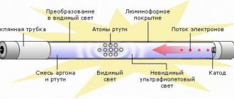
A fluorescent lamp (LL) is a glass tube filled with an inert gas (Ar, Ne, Kr) with the addition of a small amount of mercury. At the ends of the tube there are metal electrodes for applying voltage, the electric field of which leads to gas breakdown, the occurrence of a glow discharge and the appearance of electric current in the circuit. The glow of the gas discharge is pale blue and very weak in the visible light range.
But as a result of an electrical discharge, most of the energy passes into the invisible, ultraviolet range, the quanta of which, entering phosphorus-containing compounds (phosphor coatings), cause a glow in the visible region of the spectrum. By changing the chemical composition of the phosphor, different glow colors are obtained: for fluorescent lamps (FLLs) various shades of white have been developed, and for decorative lighting you can choose lamps of a different color. The invention and mass production of fluorescent lamps is a step forward compared to low-efficiency incandescent lamps.
Why do fluorescent lamps burn out?
The lamp itself is a glass bulb of various geometric shapes, made of fragile quartz glass. Its inner walls are covered with phosphor - a material capable of converting the radiation spectrum of ultraviolet wavelengths into the visible part of radiation - daylight. Quartz loses its transparency over time.
External mechanical influences on the flask can lead to the appearance of microcracks in its structure, which can result in air entering the sealed cavity. This leads to burnout of the LDS. To glow, a glow discharge is required inside the housing, which is provided by the cathodes of the device, which are tungsten filaments in the form of spirals heated by electric current.
They are coated with a layer of alkali metal to extend the life of the lamp, which crumbles when turned on and off frequently. This, in turn, leads to overheating of the cathode and its failure. Over time, the electrode's emissivity, or its ability to emit electrons from its surface, decreases. Their number is no longer capable of supporting a glow discharge.
Halogen lamp test sequence
We will also check with a multimeter. To do this, set the device to a mode for measuring the minimum resistance.
Attention! We do not touch the light bulb with our bare hands. If the skin touches the flask, a fatty imprint appears. Subsequently, the light bulb will heat up more in this place, which will shorten its service life or lead to complete failure. That's why we wear gloves.
- put a light bulb next to the device;
- we take the probes in our hands;
- apply to the terminals of the light bulb.
The readings depend on the type of light bulb and how much it has cooled since the previous turn on. The resistances will also be different for a household lamp of 220 volts and for a car lamp of 12 volts, but in any case the resistance value will be in the range from 0.5 Ohm to units of Ohm. If the value tends to infinity, then the lamp is considered inoperative.
Troubleshooting and Troubleshooting
To begin with, we must remember that an electroluminescent lamp performs its lighting functions only when all its components work in harmony - the lamp itself, the ballast, which can be either electromechanical or electronic. Thus, the reasons for the malfunction of the lamp can be either in the circuitry of the ballasts, or it can be a failure of the LDS due to its aging or violation of operating conditions.
It is best to check a fluorescent lamp (lamp) if you have a working analogue. It is necessary to provide convenient access to all its components. In this way, you can correctly analyze the malfunction and give recommendations for elimination, even if you repair it yourself. We'll tell you how to check a fluorescent lamp at home.
Integrity of electrode spirals
The electrode spirals are located inside the gas-filled LDS tube and during production are soldered to the legs of the lamp bases. They are located in the end parts of the flask. Thus, using a multimeter in resistance measurement mode, you can ring a fluorescent lamp.
Preparatory work
No special skills in handling electrical measuring instruments are required. In addition to a multimeter, the only thing you may need to successfully test light bulbs is gloves. Some models of electric light sources must not be handled with bare hands, otherwise the grease marks left on the surface of the lamp can lead to rapid failure of the product. You may also need rubbing alcohol and an old toothbrush to clean the contacts. If the light bulb has been used in a humid environment, a fairly strong oxide film can form on its metal elements, which often causes a false conclusion that the electric light source is faulty. You can also use universal WD-40 for this purpose.
Before performing a diagnostic operation, you should also make sure that the measuring device is in working order. For this purpose, it is enough to switch the device to the “ringing” mode and connect the positive and negative probes. By the sound signal you can determine the serviceability of the multimeter. If it is not possible to check the multimeter in this way, the device should be switched to resistance measurement mode. The serviceability of the tester can also be established by connecting the contacts, but, in this case, a numerical display of resistance (about 1 Ohm) should appear on the indicator.
The safety of performing the diagnostic operation is paramount, therefore, if you are not sure that the phase wire is connected to the lamp through the switch, it is recommended to turn off the safety circuit breakers in the electrical panel before removing it from the socket.
Electronic ballast for fluorescent lamps: connection instructions
At the moment, the consumer has not yet appreciated all the advantages of the improved trigger mechanism. The most important reason is the high price level for equipment of this type. You can find out about the motion sensor for turning on the light and tips on how to choose here.
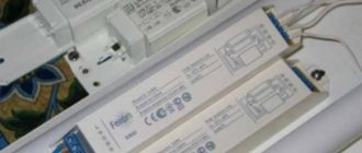
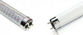
The photo shows an electronic ballast for fluorescent lamps
Principle of operation
The whole principle of operation of fluorescent lamps with electronic ballast comes down to the fact that the electric current passes through the rectifier and enters the buffer zone of the capacitor. Afterwards the voltage is supplied to the inverter
The microcircuit is triggered at a voltage level of 5.5 V. After the voltage in the system reaches 12 V, the system enters the next phase. Preheating occurs. The electronic control unit is needed to prevent the lamp from operating incorrectly.
At the third stage, the frequency response of the half-bridge decreases, and the voltage is 600 V. Ignition occurs in 1.7 seconds. If the start-up is incorrect, the filament burns out. See the guide on how to properly solder with a soldering iron here: https://howelektrik.com/elektrooborudovanie/instrumenty/payalniki/rukovodstvo-kak-pravilno-payat-payalnikom.html.
Device
Directly on the electronic ballast board is located:
- A filter that prevents the spread of electromagnetic interference.
- Rectifier - converts direct electrical current into alternating current.
- Anti-aliasing filter.
- Power factor correction.
- Half-bridge inverter.
- Protection against voltage surges.
- Throttle.
Types and characteristics
At the moment, you can use the following ballast options for fluorescent lamps:
- electronic ballasts for tubular fluorescent lamps - in this case, the electronic ballast makes it possible to continuously operate and “produce” diffused light, and on top of everything else, such a device has increased energy efficiency.
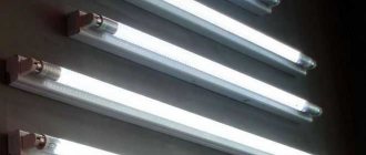
The photo shows an electronic ballast for tubular fluorescent lamps
Ballast for T8 Navigator fluorescent lamps in the photo
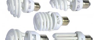
The picture shows a compact fluorescent lamp with electronic ballast
Integrated controllers for fluorescent lamp ballasts in the photo
Scheme
The figure shows a diagram of an electronic ballast for 4 fluorescent lamps
- Inclusion
- Preheat
- Arson
- Combustion
At the moment, the electronic ballast circuit for fluorescent lamps with a power of 36w is very common
There is also another balance option for turning on fluorescent lamps - inductive ballast. Its work is based on electromagnetic induction.
Switching diagram for fluorescent lamps with inductive ballast
Connection
Connecting a fluorescent lamp to an electronic ballast in the diagram
- Prepare EB and lamp.
- Remove the old filling from the lamp. Attach the EB box.
- On the one hand, electronic devices connect to the network - two wires.
- At the output from the EB, I connect the wires to the two poles of the lamp.
- Connect the device to an outlet.
Typical ballast circuit
The electronic ballast design uses an active power factor correction, ensuring compatibility with the electrical network. The basis of the corrector is a powerful boost pulse converter controlled by a special integrated circuit. This provides rated operation with a power factor close to 0.98. The high value of this coefficient is maintained in any operating mode. Voltage changes are allowed in the range of 220 volts + 15%. The corrector ensures stable illumination even with significant changes in network voltage. To stabilize it, an intermediate DC circuit is used.
An important role is played by the mains filter, which smoothes out high-frequency ripples of the supply current. Together with the corrector, this device strictly regulates all components of the consumed current. The line filter input is equipped with a protective unit with a varistor and a fuse. This allows you to effectively eliminate network overvoltages. A thermistor having a negative temperature coefficient of resistance is connected in series with the fuse, which ensures that the input current surge is limited when the electronic ballast is connected from the inverter to the network.
In addition to the main elements, the ballast circuit for fluorescent lamps requires the presence of a special protection unit. With its help, the status of the lamps is monitored, as well as their shutdown in case of malfunction or absence. This device monitors the current consumed by the inverter and the voltage supplied to each lamp. If during a certain period of time the specified voltage or current level exceeds the set value, then the protection is triggered. The same thing happens during a load circuit break.
The executive element of the protective unit is a thyristor. Its open state is maintained by current passing through a resistor installed in the ballast. The value of the ballast resistance allows the thyristor current to maintain the on state until the supply voltage is removed from the electronic ballast.
The electronic ballast control unit is powered through a mains rectifier when current passes through the ballast resistor. Reducing the power of the electronic ballast and improving its efficiency allows the use of smoothing circuit current. This circuit connects to the point where the inverter transistors connect. Thus, the control system is powered. The construction of the circuit ensures that the control system is launched at the initial stage, after which the power circuit is started with a slight delay.
Electronic ballast for fluorescent lamps: connection instructions
At the moment, the consumer has not yet appreciated all the advantages of the improved trigger mechanism. The most important reason is the high price level for equipment of this type. You can find out about the motion sensor for turning on the light and tips on how to choose here.
The photo shows an electronic ballast for fluorescent lamps
Principle of operation
The whole principle of operation of fluorescent lamps with electronic ballast comes down to the fact that the electric current passes through the rectifier and enters the buffer zone of the capacitor. Afterwards the voltage is supplied to the inverter
The microcircuit is triggered at a voltage level of 5.5 V. After the voltage in the system reaches 12 V, the system enters the next phase. Preheating occurs. The electronic control unit is needed to prevent the lamp from operating incorrectly.
At the third stage, the frequency response of the half-bridge decreases, and the voltage is 600 V. Ignition occurs in 1.7 seconds. If the start-up is incorrect, the filament burns out. See the guide on how to properly solder with a soldering iron here: https://howelektrik.com/elektrooborudovanie/instrumenty/payalniki/rukovodstvo-kak-pravilno-payat-payalnikom.html.
Device
Directly on the electronic ballast board is located:
- A filter that prevents the spread of electromagnetic interference.
- Rectifier - converts direct electrical current into alternating current.
- Anti-aliasing filter.
- Power factor correction.
- Half-bridge inverter.
- Protection against voltage surges.
- Throttle.
Types and characteristics
At the moment, you can use the following ballast options for fluorescent lamps:
- electronic ballasts for tubular fluorescent lamps - in this case, the electronic ballast makes it possible to continuously operate and “produce” diffused light, and on top of everything else, such a device has increased energy efficiency.
The photo shows an electronic ballast for tubular fluorescent lamps
Ballast for T8 Navigator fluorescent lamps in the photo
The picture shows a compact fluorescent lamp with electronic ballast
Integrated controllers for fluorescent lamp ballasts in the photo
Scheme
The figure shows a diagram of an electronic ballast for 4 fluorescent lamps
- Inclusion
- Preheat
- Arson
- Combustion
At the moment, the electronic ballast circuit for fluorescent lamps with a power of 36w is very common
There is also another balance option for turning on fluorescent lamps - inductive ballast. Its work is based on electromagnetic induction.
Switching diagram for fluorescent lamps with inductive ballast
Connection
Connecting a fluorescent lamp to an electronic ballast in the diagram
- Prepare EB and lamp.
- Remove the old filling from the lamp. Attach the EB box.
- On the one hand, electronic devices connect to the network - two wires.
- At the output from the EB, I connect the wires to the two poles of the lamp.
- Connect the device to an outlet.
Switching on two fluorescent lamps through a ballast involves parallel connection in the circuit. Only in this way will all lighting elements receive sufficient voltage for uniform operation of the devices.
Scheme for connecting two fluorescent lamps through ballast
How to check electronic ballast for fluorescent lamps?
The picture shows a device for testing lamps, including fluorescent ones
Malfunctions and repairs
It goes without saying that any equipment can sooner or later break down or malfunction. In other words, any device sometimes requires repairs and additional maintenance.
The photo shows the electronic ballast disassembled
If, due to a malfunction of the ballast for fluorescent lamps, smoke starts to appear, then it will be necessary to completely replace this element, because the smoke indicates that the component has burned out.
Repair of electronic ballast in the photo
Cost of electronic ballast for fluorescent lamps
If you need to purchase electronic ballast for fluorescent lamps, you need to contact stores that specialize in electronics or lighting equipment. The cost of this type of equipment will vary from 150 to 1200 rubles.
Where to buy electronic ballast for fluorescent lamps?
Where to order in Moscow:
- Online store Rulight.ru Moscow, Konstantin Simonov St., 5 Contact phone: 8 (495) 7883548 (multi-channel);
- Trading company Ampertorg Moscow, st. Tovaricheskaya house 6 k.1 Contact phone number;
- Online store Elektropara Moscow, st. Dokukina 10 building 10 Contact phone number.
Where to order in St. Petersburg:
- Torgovaya St. Petersburg, st. Bestuzhevskaya, 10, office 2604 (TC “Bestuzhevsky Dvor”) Contact phone number;
- Snabelektro company, St. Petersburg st. Vatutina house 17, Lit.B, Contact phone;
- Energy Saving Technologies Company, St. Petersburg, 192148 St. Petersburg, Elizarova Ave., 38 letter R, Contact phone: +7-812-3654217.
Video
Watch the video for a description of the 36 W electronic ballast:
So it turns out that this type of lamp, when using an electronic balance, begins to work several times better. In addition, the response period of the device and its operating time are significantly reduced.
Source: howelektrik.com
Operating principle of electronic ballast
The action of electronic ballasts is directly related to the operating principle of the fluorescent lamp itself. The main stage is its launch, during which certain conditions must be met. First of all, both filaments are heated, after which they are supplied with high voltage, about 600 volts. The value of the ignition voltage is directly dependent on the length of the glass tube. The shorter the lamp and the lower its wattage, the lower the required starting voltage will be.
At the initial stage, the input mains voltage is rectified to a constant value within 260-270 V and its subsequent smoothing using an electrolytic capacitor C1. This is clearly visible in the diagram presented.
Then the work of a push-pull half-bridge converter begins, consisting of two high-voltage bipolar transistors with a p-p-p structure. These transistors perform the function of switches, and the entire circuit converts a direct voltage of 260-270 V into a voltage with a high frequency of up to 38 kHz. Due to this, the size and weight of the device are reduced.
The electronic ballast circuit includes a transformer that simultaneously performs load and control functions. Of its three windings, two four-turn windings are control windings, and one two-turn winding is working. The working winding included in the circuit creates the necessary load for the converter.
Initially, the converter is started using a symmetrical dinistor, which opens if the voltage exceeds the operating threshold at the connection points. When in the open state, it sends a pulse to the transistor base, which causes the converter to start. A capacitor located in the resonant circuit and connected directly to the lamp provides a voltage drop to the level at which the lamp lights up.
Thus, with the help of the maximum current, both filaments are heated, and the lamp is directly ignited due to the high resonant voltage on the capacitor. When the lamp is lit, the resistance decreases, but the remaining voltage resonance ensures its continued combustion. Current limitation occurs due to the inductance of the inductor. Despite such a detailed description, it actually takes less than 1 second to light a fluorescent lamp.
Checking the serviceability of the fluorescent lamp and throttle
One of the most popular sources of artificial lighting is fluorescent lamps. They consume 5-6 times less energy than standard incandescent lamps, but still shine with the same brightness. LED lamps with drivers are more economical, but due to their high cost, they have not been able to displace fluorescent lamps (FLL) from the market. With prolonged use, fluorescent lamps may lose their functionality. It is possible to fix such problems, but to do this you need to know how to check a fluorescent lamp, including using a multimeter.
What malfunctions are possible and how to eliminate them
In a situation where the level of illumination provided by fluorescent lamps is no longer stable, you need to look for reasons in order to find out whether the light source can be repaired or needs to be replaced.
Note! Checking fluorescent lamps (with a multimeter) should begin with the starter or choke, since these are the two most important elements of the light source.
Also, very often, the breakdown of a fluorescent lamp occurs due to the burnout of the tungsten filament. This is generally the most common reason for a light source to fail.
Expert opinion
It-Technology, Electrical power and electronics specialist
Ask questions to the “Specialist for modernization of energy generation systems”
How to test an inductor (inductor) using a multimeter? This device is part of the electromagnetic control equipment and, when working together with the choke, ensures the start of the process of forming a glow discharge in the LDS bulb when an alternating mains voltage is applied to the contacts of the lamp. Ask, I'm in touch!
Design and principle of operation of fluorescent lamps
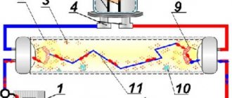
Many of the advantages of LDS are due to the fact that they are gas-discharge devices in which ultraviolet radiation is generated due to electrical discharges in mercury vapor.
There is only one peculiarity here - visible illumination from the lamp occurs only after the ultraviolet radiation is modified. Such a transformation is possible only when using those compounds that contain calcium halophosphate or other compounds with the presence of phosphors.
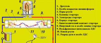
Based on the principle of operation, LDS can be equated to gas-discharge lighting sources. An inert gas is placed in a glass flask, after the air has been pumped out of it, and then 30 mg of mercury is added to the gas. Spiral-shaped electrodes, similar to an incandescent filament, are installed at both edges of the vessel. They are soldered on each side to 2 contact legs, which are placed in dielectric-type plates. The inner surface of the tube is covered with a layer of phosphor.
The daylight is turned on using a ballast - electromagnetic or electronic type. The electromagnetic device includes a main element - a choke. This is a ballast type resistance in the form of an inductive coil with a metal core, which is connected in series with a fluorescent lamp.
The choke is necessary to maintain uniformity of discharge and adjust the current if necessary. When the light bulb turns on, the inductor suppresses the starting current until the spiral filaments heat up, and then produces the maximum voltage from self-induction, as a result of which the LDS ignites.
Causes of light bulb failure
Before repairing the lamp, it must be disassembled to determine the cause of the breakdown.
The best way to solve a problem is to take systematic action. Therefore, we will carry out the work in a clear sequence:
- We prepare a set of tools.
- We dismantle the lamp.
- We look for and fix problems.
- Reassemble the lamp in reverse order.
To perform the repair you will need the following tools:
- flat screwdriver;
- multimeter;
- a 25–30 W soldering iron, as well as a soldering kit.
We carry out dismantling in this order:
- First, we detach the flask from the base. The operation should be performed with extreme caution to maintain the integrity of the base. The parts of the light bulb are connected to each other with latches. To disassemble the device, it is recommended to use a screwdriver with a thin but wide blade. One of the latches is usually located where the technical data of the light bulb is indicated. We point the screwdriver into the gap and gently turn the halves apart. Next, we move the screwdriver in a circle until the lamp is divided into two parts, and then we unfasten the base and bulb.
- Disconnect the wires going to the filaments. Two pairs of wires are attached to the bulb (they are filaments), to test for serviceability, they need to be disconnected. The threads are usually not soldered, but wound on wire pins in several turns. In this regard, detaching the threads is usually not difficult.
- We check the lamp filaments for functionality. The flask most often contains a pair of spirals with a resistance of 10–15 ohms. We check using a multimeter. If the threads are not damaged, then the problem most likely lies in the ballast. And vice versa: if the threads are damaged, the ballast is operational.
Note! It is important to act carefully so as not to accidentally break the wiring coming from the light bulb base.
Reasons for burnout of fluorescent lamps
Often the LDS burns out, which makes it similar to a traditional incandescent lamp. When turned on, an arc of electricity is formed in the bulb, as a result of which the spiral-shaped tungsten electrodes become very hot. High temperature surges lead to destruction and burnout of the threads.
To extend the service life, a layer of active alkali metal is applied to the tungsten filament. The discharge between the electrodes is stabilized and the temperature decreases, thanks to which the thread lasts much longer.
Frequent switching on/off of the lamp entails the destruction of the protective layer, it simply falls off. The discharge passing through the bare filaments heats the spiral at weak points, resulting in burnout.
Checking with a digital tester
Using a digital tester, you can check the integrity of the filaments. This can be done both in the dialing mode and in the resistance testing mode. It is necessary to set the multimeter to the desired mode and check the spiral at both ends of the tube.
In the dialing mode, if the spiral is working properly, the tester will produce a characteristic sound - a buzzer.
In the resistance test mode, if the spiral is working properly, the multimeter indicator will display a value of 5-10 Ohms.
Burnout of heating filaments is the most common failure of fluorescent lamps, which can be easily detected using a digital tester.
Where to start checking the performance of a light bulb with a multimeter
How to test a fluorescent lamp choke with a multimeter
To check, take a multimeter in continuity mode or measure small resistance and measure the inductor. A buzzer or indicator reading will indicate the presence or absence of a wire break inside the inductor.
Check the insulation for insulation breakdown; you need to set the multimeter to resistance measurement mode at the maximum limit. The multimeter indicator should show a break when it touches any of the leads and the metal case.
Starter continuity
Testing the starter with a multimeter consists of checking the neon bulb for an internal short circuit. To do this, remove the housing and use a multimeter to place any probe on one terminal of the lamp. With the second wire of the multimeter we touch the other terminal of the neon. The multimeter should show no resistance.
You can test the starter's performance without a multimeter. Pull the starter out of the socket without disturbing the rest of the circuit. Turn on the power. Using caution and making sure that the tool is well insulated, briefly short-circuit the contacts of the starter socket. The lamp of the lamp should light up if all other elements of the circuit are in working order.
What kind of lighting do you prefer?
Built-in Chandelier
Troubleshooting and Troubleshooting
The LDS is faulty in the following cases:
- does not turn on;
- flickers temporarily before turning on;
- flickers for a long time, but does not turn on;
- buzzes;
- flickers when burning.
Integrity of spiral electrodes
You can test the spiral electrode for the presence of resistance using a multimeter. The device is set to resistance measurement mode, and after that the probes are applied to the legs of the flask on both sides.
If the spiral is faulty, the multimeter will show zero resistance - the thread is broken. A whole spiral always shows a small resistance - up to 10 ohms. If at least one of the spirals is faulty, the lamp must be replaced. It cannot be restored.
Faults in the electronic ballast
To check the serviceability of the electronic ballast, it must be replaced with a working one. If the lamp lights up, it means that it was the cause of the breakdown. You can fix a broken ballast yourself. First you need to replace the fuse with a similar model with the same characteristics. If the threads glow weakly, it means there is a breakdown in the capacitor between them. It is also replaced by a similar one, but with an operating voltage of 2 kV. weak models will burn out quickly.
Transistors may burn out due to voltage surges. They need to be changed. You can take new ones from old ballasts. After replacement, you need to check the fluorescent lamp using a 40 W lamp.
How to check the choke of a fluorescent lamp
Before checking the choke of a fluorescent lamp with a multimeter, you need to familiarize yourself with the main signs of its failure:
- hum of a lighting fixture;
- the lamp turns on and goes out after a while, getting dark around the edges;
- LDS overheats;
- “snakes” appear inside the tube;
- The lamp flickers a lot.
To check the choke for operability, you need to remove the starter from the lamp, and then close the contacts in its socket. Then the lamp is removed and the contacts in both sockets are also short-circuited. The multimeter is set to measure resistance, after which its probes are connected to the contacts in the lamp socket. If there is a break, the device will show endless resistance. If there is an interturn short circuit, the device will show a zero value.
How to check the starter
If the lamp begins to flicker immediately after switching on, but does not light up, the starter has failed. It will not be possible to test it separately from the LDS, since without voltage its contacts are open.
Checking the serviceability of the starter is possible using another method - by connecting it in series with an incandescent lamp to a standard electrical network.
The main reason for failure is that the bimetallic plate wears out greatly.
How to check the capacitance of a capacitor with a tester
If the LDS capacitor is faulty, its efficiency indicator decreases to 35-40%. For lighting devices with a power of no more than 40 W, a capacitor with a capacity of 4.5 μF is sufficient. If it is less than this norm, the efficiency will be reduced; if it is more, the lighting will blink.
To carry out the measurement, the capacitor must be ringed with a multimeter. When the probes touch the outputs of a part, the device demonstrates endless resistance. When this indicator is less than 2 MΩ, this is a symptom of significant current leakage.
Electronic ballast circuits 4×18 (2×36)
EB 4×18 is used with inverting capacitors with a capacity of 5 pF. Thus, the resistance of this module can increase to 40 Ohms. Another feature of this circuit is the location of the choke element (it can be found below the dinistor).
Electronic ballast circuit 4×18
The circuit above uses only one transistor. The transformer performs the function of reducing and rectifying the current. This element protects the device from overloads, but there is also a fuse in the circuit.
Scheme for "Navigator"
Another 4×18 EB is “Navigator”. The circuit also contains a step-down transformer and a transistor. The main difference is the presence of a special regulator that allows you to change the output voltage. The capacitive resistor also distinguishes this circuit from the previous one.
Note! Here two capacitors with a capacity of 5 and 7 pF are used. This allows you to create resistance up to 40 ohms
This circuit does not use a fuse.
Scheme 2x36
The 2x36 ballast circuit includes a transceiver for expansion. The device is connected using an adapter device. As in the previous versions, there are capacitors, but their capacitance is smaller, only 4 pF. The circuit is distinguished by the presence of thyristors and frequency regulators. For most models of modules of this type, you can see two rectifiers in the circuit. The operating voltage of such a ballast is 200 V, and the frequency is 55 Hz.
Electronic ballast 4x18 is a necessary device to maintain the integrity of fluorescent lamps. There are several schemes to connect it. You can choose the most suitable and easiest to implement.
Turning on a fluorescent lamp without a choke
A burnt-out fluorescent lamp can be returned to work if it is connected to the circuit using constant voltage, excluding the starter and throttle element. Using a full-wave rectifier with voltage doubling will help here. If after some time the brightness of the lamp decreases, it must be turned over in the lamp, as a result of which the connection poles will change.
This scheme involves the use of radioelements with a voltage value of no more than 900 V. This is the value that the LDS reaches at startup.
Connecting and repairing a ballast for fluorescent lamps
Ballast for a gas-discharge lamp (fluorescent light sources) is used to ensure normal operating conditions.
Another name is ballast (ballast). There are two options: electromagnetic and electronic. The first of them has a number of disadvantages, for example, noise, the flickering effect of a fluorescent lamp. The second type of ballast eliminates many of the disadvantages in the operation of the light source of this group, and therefore is more popular. But breakdowns in such devices also happen. Before discarding, it is recommended to check the ballast circuit elements for faults. It is quite possible to carry out electronic ballast repairs yourself.
Connection diagram for burnt out lamps
Fluorescent lamps often become unusable due to filament burnout. You can restore a second life to such a lamp using an unconventional starting scheme, repeatedly tested by folk craftsmen.
From the table you can find out the nominal values of radioelements for LDS with different powers. Limiting resistors R1 must be made of wire.
You can repair LDS at home if you follow the diagrams and follow certain instructions. Such knowledge makes it possible to extend the operational period of the lighting device.
Source: strojdvor.ru
How to choose
- When choosing a ballast for a fluorescent lamp, you need to pay attention to the power of the module. It must match the power ratings of the lighting fixture. If these requirements are not met, the device will not function properly;
- Price. Electromagnetic elements are inferior in price to electronic ones. But, technically, they are outdated and are inferior in operation due to additional energy costs and bulkiness;
- The cost of electronic ballasts is higher, but practicality and energy savings make up for this disadvantage.
Branded manufacturers include high-quality parts that ensure correct operation over a long period of time. Such devices will be able to fulfill the warranty period.
It is necessary to pay attention to the presence of the IP2 marking affixed to the products. This indicates that the device has the required level of protection and is also protected from small elements entering the housing. The design prevents direct user contact with elements supplying electricity.
The temperature range has been significantly expanded. The devices can operate at temperatures from -20 °C to + 40 °C.