Main functions
It is not possible to connect fluorescent light sources directly to the electrical network. There are the following reasons for this:
- to create a persistent discharge in a fluorescent lamp, it is necessary to preheat its electrodes and apply a starting pulse to them;
- Since gas-discharge light sources have a negative differential resistance, they are characterized by an increase in current strength after entering the operating mode. It must be limited to prevent the light source from failing.
Based on the reasons described above, it is necessary to use ballasts.
Electromagnetic type ballasts
Operating principle of electronic ballast
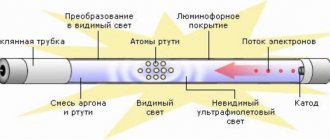
The action of electronic ballasts is directly related to the operating principle of the fluorescent lamp itself. The main stage is its launch, during which certain conditions must be met. First of all, both filaments are heated, after which they are supplied with high voltage, about 600 volts. The value of the ignition voltage is directly dependent on the length of the glass tube. The shorter the lamp and the lower its wattage, the lower the required starting voltage will be.
Principle of operation
Let's consider the principle of operation of an electromagnetic choke using the example of a typical connection diagram for gas-discharge lamps.
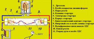
Typical connection diagram
The diagram shows:
- EL – gas-discharge (fluorescent) type lamp;
- SF is a starter, it is a device consisting of a flask filled with an inert gas, inside it there are bimetal contacts. A capacitor is installed parallel to the flask;
- LL – choke (electromagnetic);
- lamp spirals (1 and 2);
- C – capacitor (compensates for reactive power), its capacity depends on the power of the lamp, the correspondence table is shown below.
| Gas discharge source power (W) | Capacitor capacity (uF) |
| 15 | 4,50 |
| 18 | 4,50 |
| 30 | 4,50 |
| 36 | 4,50 |
| 58 | 7,00 |
There are devices in the circuits of which there is no compensating capacitor; this is unacceptable, since reactive load leads to the following negative consequences:
- there is an increase in power consumption, which leads to increased energy consumption;
- The service life of the equipment is significantly reduced.
Now let's move directly to the principle of operation of the above typical scheme. Conventionally, it can be divided into the following stages:
- when connected to the mains, a current begins to flow through the circuit inductor “LL” – spiral “1” – starter “SF” – spiral “2”, the strength of which is from 40 to 50 mA;
- under the influence of this process, an inert gas is ionized in the starter flask, which leads to an increase in current strength and heating of the bimetallic contacts;
- the heated electrodes in the starter close, this causes a sharp increase in current, up to approximately 600 mA. Its further growth limits the inductance of the inductor;
- due to the increased current in the circuit, the spirals (1 and 2) are heated, as a result of which electrons are emitted by them, the gas mixture is heated, which leads to a discharge;
- Under the influence of the discharge, ultraviolet radiation appears, which hits the phosphor coating. As a result, it glows in the visible spectrum;
- when the light source “lights up”, its resistance decreases, and accordingly, the voltage at the inductor decreases (up to 110 V);
- The starter contacts cool down and open.
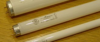
Tandem connection
Below is a diagram where two fluorescent type lamps are connected in series.
Tandem connection diagram
The operating principle of the presented circuit does not differ from a standard connection, the only difference is in the parameters of the starters. For a two-lamp connection, starters are used whose “breakdown” voltage is 110 V (type S2), for a single-lamp connection - 220 V (type S10).
Starters S10 and S2 for 220 and 110 V respectively
How to connect
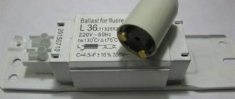
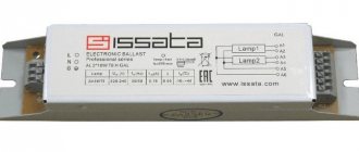
The appearance of electronic ballasts resembles a block with external terminals, inside of which a printed circuit board is installed. Depending on the type of this board, a certain number of fluorescent lamps are connected.
The connection process itself is quite simple and does not require any special knowledge. It consists of several stages:
- The first and second output connectors of the device are connected to the corresponding contact pair on the lighting device.
- Next, supply voltage is applied to the input.
If you need to make a connection according to a separate circuit, you should remember that the inductor must be connected to the break in the supply wire. In parallel with it, a starter is connected to the electrodes. The electronic ballast, starter connectors and filaments must be connected in series.
Features of electromagnetic type chokes
Speaking about the features of electromagnetic ballasts, it should be noted that the only advantages of these devices are their relatively low price, simple operation and simple installation. The classical connection scheme has much more disadvantages :
- the presence of a bulky and “noisy” throttle;
- starters, unfortunately, are not reliable;
- the presence of a strobe effect (the lamp flickers at a frequency of 50 Hz) causes increased fatigue in a person, which leads to a decrease in his performance;
- when the starters fail, a false start occurs, that is, the lamp flashes several times before “lighting up”, this reduces the working life of the light source;
- approximately 25% of the power is spent on electromagnetic ballast, resulting in a significant reduction in efficiency.
The use of electronic ballasts allows you to get rid of most of the disadvantages listed above.
Electronic ballast (EPG)
Electronic ballasts appeared en masse not so long ago, about thirty years ago, and now they have practically replaced electromagnetic devices. This was facilitated by numerous advantages over the classical switching circuit; we will name the main ones:
- increasing the luminous efficiency of fluorescent lamps due to high-frequency discharge;
- absence of noise characteristic of low-frequency electromagnetic chokes;
- reducing the gating effect significantly expanded the scope of application;
- the absence of a false start increases the service life of luminescent sources;
- Efficiency can reach 97%;
- compared to electromagnetic type ballasts, energy consumption is reduced by 30%;
- there is no need to compensate for reactive load;
- Some models of electronic devices provide control of the power of the lighting source; this is done by adjusting the frequency in the voltage converter.
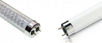
EPLA appearance and internal structure
It is also worth noting: due to the absence of a bulky inductor, it became possible to reduce the size of the electronic ballast, which made it possible to place it in the base. This significantly expands the scope of application, making it possible to use it in lighting devices instead of sources that use a filament.
Electronic ballast located in the base
As an example, let's take a simple electronic ballast circuit, typical of most inexpensive devices.
Diagram of a typical electronic ballast
List of elements:
- resistor ratings: R1 and R2 -15 Ohm, R3 and R4 – 2.2 Ohm, R5 – 620 kOhm, R6 – 1.6 Mohm;
- capacitors used: C1 – 47 nF 400 V, C2 – 6800 pF 1200 V, C3 – 2200 pF, C4 – 22 nF, C5 – 4.7 µF 350 V;
- diodes: VD1-VD7 – 1N400;
- transistors: T1 and T2 – 13003;
- diode triac VS – DB3.
Concluding the topic of electronic ballasts, it is necessary to note that their significant drawback is the relatively high cost of high-quality devices. As for inexpensive models, their reliability leaves much to be desired.
Converter for fluorescent lamp circuit
This converter can be used to power fluorescent lamps with a power of up to 20 W from a battery or other autonomous source with a voltage of 6.12 V, for example, in camping conditions.
Its circuit, similar to those widely used in many imported portable battery-powered fluorescent lamps, is shown in Fig. 1. The basis of the converter - a blocking oscillator on transistor VT1 and transformer T1 - generates short pulses with a frequency of 30.40 kHz and an amplitude of 400 V, which are supplied to the fluorescent lamp EL1. Due to the high pulse frequency and inertia of the phosphor, the blinking of the lamp is completely invisible.
When adjusting the frequency using variable resistor R2, the pulse duration remains constant. Their duty cycle changes, and with it the brightness of the lamp. The higher the resistance introduced, the lower the frequency and the higher the duty cycle, the lower the brightness of the lamp and the lower the current consumed from the power source (for example, a car battery). When testing the converter with the F13W lamp, the current was 70 mA at minimum and 800 mA at maximum brightness.
The regulator is assembled on a single-sided printed circuit board measuring 35x85 mm, a fragment of which is shown in Fig. 2. On the rest of it there are (glued or fastened with screws) transformer T1 and transistor VT1 with a heat sink. After soldering the leads, the housing of the variable resistor R2 is also fixed with glue. The appearance of the mounted board is shown in Fig. 3.
It is placed in a housing of a suitable size made of insulating material, leading the axis of the variable resistor into the hole on the front wall. The EL1 lamp can be installed in a standard fixture or one made independently from scrap materials.
Instead of the KT841A transistor, you can use the KT805A or KT847A. The heat sink area must be at least 15 cm2.
The magnetic core of the T1 transformer is an armored BZO made of M1500NMZ ferrite. It is assembled with a non-magnetic gap of 0.2. 0.5 mm. Winding I - 24 turns PEV-2 0.38. 0.41 mm (in two wires), II - 7 turns of the same, but single wire, III - 190 turns of PEV-2 0.18 wire. 0.2 mm. The latter is reliably isolated from other windings and the magnetic circuit with lacquered cloth or insulating tape.
Any fluorescent lamps with a power of 4.20 W can be connected to the converter, including those with burnt-out filaments. If the lamp power is less than 10 W, the number of turns of winding III should be reduced.
The converter will be able to operate at a lower (down to 6 V) supply voltage if the number of turns of winding II is reduced in proportion to the voltage. However, its efficiency is noticeably reduced, so using lamps with a power of more than 10 W in this case is not recommended.
When setting up the converter, resistor R1 is selected in such a way that in the right (according to the diagram) position of the variable resistor R2 slider, the brightness of the lamp is subjectively perceived as nominal, corresponding to its connection to the network according to a standard circuit with a “ballast” choke. If moving the slider to the opposite position reduces the brightness insufficiently or excessively, the value of the variable resistor should be increased or decreased accordingly.
Source
Connection without ballast
If necessary, gas-discharge light sources can be connected to the power supply without electromagnetic or electronic ballast. The diagram of such a connection is shown below.
Throttleless connection method
To implement such a connection you will need:
- fluorescent lamp - 40 W and incandescent lamp - 60 W (the latter will work as a ballast resistance);
- two capacitors 0.47 uF 400 V (play the role of a multiplier);
- diode bridge KTs404A or similar, you can use four diodes designed for a current of at least 1 A and a reverse pulse voltage of 600 V.
This circuit is inferior in its parameters to connection using an electromagnetic choke and electronic ballasts. It is provided for informational purposes only.