Introduction
The exponential growth of LED lighting is accompanied by an expanding selection of chips for driving LEDs. Switching LED drivers have long replaced linear current sources, which consume significantly more energy. All applications, from flashlights to stadium scoreboards, require precise control of regulated current. In many cases, it is necessary to change the output intensity of LEDs in real time. This function is commonly referred to as LED dimming. This article introduces the basic concepts of LED theory as well as some brightness control techniques for switching LED drivers.
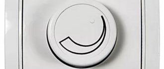
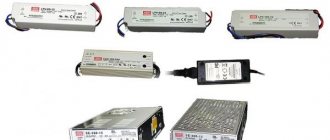
Ready-to-use dimmers
A regulator that is sold ready-made for LED lamps is called a dimmer. The frequency of the pulses created by them is high enough so that we do not feel flickering. Thanks to the PWM controller, smooth adjustment is possible, allowing you to achieve maximum brightness or dimming of the lamp.
By installing such a dimmer into the wall, you can use it like a regular switch. For exceptional convenience, the LED brightness control can be controlled by a radio remote control.
The ability of lamps based on LEDs to change their brightness opens up great opportunities for holding light shows and creating beautiful street lighting. And it becomes much more convenient to use a regular pocket flashlight if you can adjust the intensity of its glow.
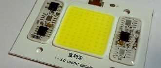
LED brightness and color temperature
LED brightness
The concept of brightness of visible light emitted by an LED is quite simple to explain. The numerical value of the perceived brightness of an LED can be easily measured in luminous flux density units called candelas (cd). The total output power of an LED is measured in lumens (lm).
It is also important to understand that the average forward current of an LED determines the brightness of the LED. Figure 1 shows the LED forward current as a function of light output. It can be seen from the figure that this dependence is linear over a wide range of applied values of the forward current IF. Note that as IF increases, the nonlinearity increases. When the current begins to go beyond the linear region, a decrease in efficiency (lm/W) occurs.
LED color temperature
Operating an LED beyond its ramp-up range causes the LED output power to be converted into heat. This, in turn, creates a load on the LED driver and complicates the heat dissipation system.
Color temperature is an indicator that describes the color of the LED and is indicated in the technical documentation for the LED. LED color temperature is defined over a range of values and varies with forward current, junction temperature, and LED life. Lower color temperatures correspond to red-yellow colors (which are called warm), and higher color temperatures correspond to blue-green colors (cool). Many color LEDs specify a predominant wavelength rather than a color temperature, and also allow wavelength shifts.
Methods for adjusting LED brightness
There are two popular methods for adjusting the brightness of LEDs in switching driver circuits: PWM dimming and analog dimming. Both methods control time-averaged current through an LED or string of LEDs, but there are differences between them that become clear when discussing the advantages and disadvantages of the two types of control circuits.
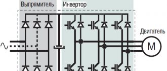
Figure 2 shows a switching LED driver enabled in a buck topology. The VIN voltage should always be higher than the LED voltage plus the RSNS voltage. The current in the inductor is the LED current. Current stabilization occurs by monitoring the voltage at the CS pin. When the voltage at the CS pin begins to fall below the set voltage, the duty cycle of the current pulses flowing through the L1 coil, the LED, and the RSNS resistor increases, thereby increasing the average LED current.
Analogue dimming of LEDs involves adjusting the LED current. In simple terms, it is adjusting the constant current level of the LED. Analog adjustment can be done by adjusting the current control resistor RSNS or by controlling the analog voltage at the DIM pin of the chip. Figure 2 shows these two analog adjustment methods.
Why do you need to adjust brightness?
Any comparison table clearly shows the relationship between electricity consumption and lamp brightness. A dimmer provides a real opportunity to save money, as it allows you to reduce the intensity of the light flux, for example, in a room where the family is currently watching TV, or increase the lighting while receiving guests at the table.
Many kids are afraid of the dark, and older people have trouble finding their way around when the lights are off. In both cases, the dimming option will come in handy. But it should not be present in the general switch, but in the circuit of the LED electrical appliance.
During the evening rest period, the light can be made softer. Whereas, if it is necessary to perform any work, increase the lighting to the required maximum. It should be noted that some luminaire models are equipped with remote or automatic control, taking into account time intervals or the fact of object movement within the coverage area of a specially installed sensor.
Find out the price
Analogue brightness control
Analog adjustment using RSNS trim
From Figure 2, it can be seen that a change in RSNS resistance results in a corresponding change in LED current at a fixed reference voltage at the CS pin. If a potentiometer could be found that could drive high LED current and also operate down to 1 ohm, then this would be a feasible method for adjusting the brightness of LEDs.
Analog regulation using constant voltage control on the CS pin
A more complex control method is to directly control the LED current by applying voltage to the CS pin. The voltage source is usually included in the feedback circuit, the current in which is generated by the amplifier (see Fig. 2). The LED current can be controlled by the amplifier gain. Using a feedback circuit, you can implement current and thermal protection of the LED.
The disadvantage of analogue control is that the color temperature of the emitted light may vary depending on the LED current. In cases where the color of an LED is a critical parameter, or a particular LED exhibits noticeable changes in color temperature when the LED current changes, adjusting the brightness by adjusting the LED current becomes unacceptable.
Should I use a dimmer for LED strip?
Definitely worth it. Even a non-professional can install such a device, but the dimmer itself greatly expands the functions and capabilities of the LED strip. For example, you can refuse a large number of lamps of different power, since the same strip will shine with different brightness, replacing both a large chandelier and a small night light.
Such lighting is very convenient in a children's room - when the child falls asleep, you can simply dim the light to a minimum, without worrying about the wiring or the fact that the child will wake up at night in the dark and get scared.
Fans of home parties will definitely love the lighting effects that can be created using a dimmer with an audio input. And this is only a small part of the ways to use dimmers and LED strips in ordinary apartments and houses.
PWM adjustment
With the PWM control method, current is passed through the LED for short periods of time. The frequency of these start-restart cycles of current must be higher than the frequency detectable by the human eye to prevent the flicker effect. Typically a frequency of about 200 Hz or higher is used. The brightness of the LED in this case is proportional to the duty cycle of the adjustment signal in accordance with the formula:
IDIM-LED - DDIM ILED,
where IDIM-LED is the average LED current, DDIM is the duty cycle of the regulation signal, ILED is the rated LED current, which is set by the RSNS resistor, as shown in Figure 3.
Many modern LED drivers are equipped with a dedicated PWM adjustment pin (DIM) that can accept a wide range of PWM signals and amplitudes, allowing easy interfacing with external logic. The signal applied to the DIM pin turns off only the output of the circuit, leaving the internal blocks in the operating state to prevent delay in startup of the chip. You can also use the output enable pin and other logic functions of the chip.
Controlling an LED Driver Using a PWM Signal
2-wire PWM control
2-wire PWM control is a popular method used in automotive interior lighting systems. Since VIN is modulated below 70% of VIN-NOMINAL, the VINS pin (see Figure 3) detects the voltage change and converts the input PWM signal to a corresponding PWM output signal. The disadvantage of this method is that the converter's power supply must contain a circuit that generates a PWM signal at its DC output.
Fast PWM control using a shunt device
Due to the delay in turning off and starting the converter output, there are restrictions on the frequency of the PWM control signal and the range of duty cycles. To reduce this delay, an external bypass component such as an FET can be connected in parallel with the LED or string of LEDs to provide a path for the converter output current to bypass the LED, as shown in Figure 4.
| Rice. 5. Comparison of turn-on delay using DIM pin and shunt FET |
The current in the inductor does not disappear when the LED is turned off, which eliminates the long delay in its rise and fall. The delay time is now determined by the minimum rise and fall time of the shunt device signal. Figure 4 shows the LM3406 with a shunt FET, and Figure 5 compares the LED turn-on/off latency using the DIM pin and the shunt FET. These measurements were performed at 10 nF output capacitance using a Si3458 shunt FET.
When shunting LED current when using switching converters, precautions should be taken due to possible output current surges when the FET is turned on. The LM340x family of LED drivers are time-controlled converters with no current surge. The output capacitance rating on the LED must be small to ensure maximum switching speed.
The disadvantage of the fast brightness control circuit is the loss of efficiency. When the shunt device is turned on, power dissipation equal to VSHUNT DEVICE ILED is lost as heat. Using a FET with a low Rds(on) value minimizes efficiency losses.
LM3409 provides multiple brightness adjustment functions
| Rice. 6. Connection diagram for LM3409 with analog brightness control |
National Semiconductor's LM3409 is a unique LED driver that provides the necessary functionality for simple analog and PWM dimming. This device provides four possible ways to realize LED brightness control.
- Analog adjustment using direct control of the IADJ pin from a voltage source in the range 0...1.24 V.
- Analog adjustment using a potentiometer connected between the IADJ pin and ground.
- PWM control using the resolution pin.
- PWM control using external shunt FETs.
The LM3409 circuitry for analog adjustment using a potentiometer is shown in Figure 6. An internal 5-µA current source creates a voltage drop across the RADJ, which in turn allows the internal current sensitivity threshold to be varied. For the same purpose, the IADJ pin can be directly driven from a constant voltage source.
Figure 7 shows a graph of the LED current versus the resistance of the potentiometer connected between the IADJ pin and GND. The flat part of the curve at a current value of 1 A corresponds to the maximum rated current of the LED, which is set by the current control resistor RSNS, shown in Figure 4.
Rice. 8. Dependence of LED current on voltage at pin IADJ
Both analogue dimming options are easy to implement and provide very linear LED dimming levels up to 10% of maximum. Figure 8 shows LED current as a function of IADJ pin voltage. Note that this graph shows the same maximum LED current set by the RSNS resistor.
Digital control
The standard I2C port is used to preset the I-LED current value and PWM depth, using software to program the controller's internal functions. To better illustrate the gradual change in brightness, let's take the NCP5623 controller as an example .
Before starting the PWM process, it is necessary to set the peak value of the ILED current by sending the appropriate code to the circuit as specified in the NCP5623 IC specification.
To ensure that the backlight turns on smoothly, software is needed to control all the steps used by the driver: in this case, 31 steps. A simple loop can be implemented in the microcontroller to perform this task, but the ramp signal may be corrupted by higher priority interrupts associated with real-time tasks.
A more efficient solution is to take advantage of the built-in sequence implemented in the NCP5623, which eliminates the need for a real-time microcontroller: gradual changes in brightness up or down can be triggered using a simple program, the execution of which is not affected by high-priority interrupts.
It is necessary to set the values of two registers:
- The meaning and direction of the gradual change in brightness:
– UPWARD = %101x xxxx → the last bits of [B4:B0] contain the maximum value of the ILED current; – DWNWRD = %110x xxxx → the last bits of [B5:B0] contain the minimum value of the ILED current.
- Duration and start conditions:
GRAD = %111x xxxx → the last bits of [B5:B0] contain the duration of the step.
The ILED current will ramp up from 0 to 5.5 mA, the total duration of the sequence equal to the contents of bits [B5:B0] of the GRAD register multiplied by the number of steps set by the contents of the UPWARD register. Example described above:
T=GRAD[B5:B0]•UPWARD[B5:B0] T=64•26=1664 ms
The curve shown in Fig. 3 illustrates a gradual increase in brightness; The dimming operation is carried out by appropriate programming of the DWNWRD register.
Rice. 3. Typical automatic brightness increase by the NCP5623 driver in steps of 8 ms
As we can see, the ILED current increases according to a quasi-exponential characteristic, sufficient to compensate for the sensitivity of the human eye.
Changing the brightness in the opposite direction is done by using the corresponding code of the first three bits of the data register, the rest of the sequence is carried out similarly.
Built-in registers allow dynamic control of gradual brightness changes to emulate various visual effects. For example, you can repeat the sequence created by digitally modulating the dimming and dimming periods. You can also create a sawtooth curve by combining a gradual change in brightness with a sharp change in the direction of the curve in the opposite direction.
Finally, a fairly complex backlight sequence can be achieved by combining dimming using on-chip PWM and ILED peak current modulation using the IREF pin. Effects can be achieved using a minimum of passive components around the main controller.
Obtaining technical information, ordering samples, delivery - e-mail
30V N-Channel Power MOSFETs
These 8-lead SOIC and µ8FL (WDFN) power MOSFETs offer the following features:
- low channel resistance in the open state to reduce conduction losses;
- minimum gate charge to reduce switching losses;
- low input capacitance to minimize losses in the driver.
The use of transistors improves the efficiency of circuits such as DC-DC converters and synchronous rectifiers. With a small 3.3 x 3.3 x 0.8mm design and high current rating, these cells are used in laptops, laptops, printers and other peripheral devices. NTMS4800N provides current up to 8 A, NTMS4801N - 12 A, NTMS4802N - 18 A, NTTFS4821N - 57 A, NTTFS4823N - 50 A, NTTFS4824N - 69 A.
Thyristor protection components
ON Semiconductor has introduced a new series of thyristor protection devices (TSPDs) for telecommunications equipment circuits. These devices provide excellent protective properties, are small in size and have low intrinsic capacity.
NP0080, NP0120, and NP0160 microcircuits are produced in a TSOP-5 package, have a differential capacitance of up to 3 pF, and can withstand currents of up to 50 A for 8...20 μs. They are used to protect the line between the DSL transformer and the subscriber, as well as in data access devices.
Another series of thyristor protection devices, NP-MC, are manufactured in the SMB package, have a capacitance of up to 30 pF and a current of up to 100 A. These products are offered as an alternative to gas-discharge fuses. Due to their low capacitance, they introduce minimal distortion into VDSV2+ equipment and T1/E1 circuits.
•••
How to dim an LED lamp?
Cut a piece of wax paper. Cut a piece of duct tape and place it on wax paper. Take a stapler and pierce the electrical tape through the paper. You will get a round, even sticker - peel off the paper layer to cover the LED light bulb.
Interesting materials:
What is the diameter of handball for teenagers and men? What is the diameter of the garden hose? How long should skis and poles be? How long should a mustache be? How long is long hair considered? What should the snood be? What kind of winter overalls should be for a newborn? How long should men's trousers be? Which house is warmer: frame or vulture panels? Which home Internet is better: wired or wireless?