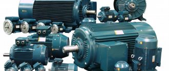
Today, electric motors are increasingly replacing hopelessly outdated gasoline units and are used both in modern transport and in numerous electronic devices. Examples of the use of these power units can be found everywhere. The vibration alert in the phone is carried out thanks to the operation of an electric motor, a modern electric bicycle also travels thanks to an electric motor, and even the “favorite” metro is all electric motors.
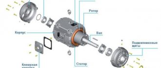
There are a huge number of types of electric motors today, but there is one important factor that will be similar for almost all of them. We are talking about the physics of how this type of device works. Note that not all of them will use the principle described below in their work, but most electric motors work this way. At a minimum, the physical effect on which all this rests is preserved. Before discussing in detail the physics of the process by which an electric motor rotates, let us first consider the design of a simple motor.
Asynchronous motor stator
The stator of an asynchronous motor is a core consisting of electrical steel plates and containing copper windings, which are laid in a certain way in the stator grooves.
As mentioned, the stator core consists of plates that are insulated from each other. There are grooves on the inside of the stator
in which the insulation is placed
Next, varnished copper wire is wound into these grooves in a certain way, which represents the stator windings
An induction motor has three “pieces” of copper wire
Which are laid in a certain way in the stator grooves at an angle of 120 degrees relative to each other.
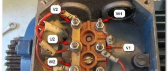
All 6 ends of the winding wires are led out into the terminal box, which is located on the motor housing.
The motor stator, or more precisely, the dimensions of the core, the number of coils in each winding and the thickness of the winding wire from which the coils are wound determine the main parameters of the motor. For example, the rated speed of the engine depends on the number of coils in each winding, and the rated power of the engine depends on the thickness of the wire with which they are wound. The number of windings for a three-phase asynchronous motor is always three. But the number of coils in each of these windings is different. Coils can be wound into one or two wires. Considering that the rated speed of the motor is inversely proportional to the rated load, we can safely say that the shaft speed of an asynchronous motor will decrease as the load increases. If, while the engine is running, its speed begins to decrease due to an increase in load, then not stopping this process can lead to a complete stop of the engine. The engine will begin to hum strongly, the rotor shaft will not spin - the coils will become very hot, followed by destruction of the insulation of the winding wire, which will lead to a short circuit and fire of the windings.
A real photo of the stator of one of the asynchronous motors looks like this.
What is an ED stator and its purpose?
The stator is the stationary part of the engine that works in tandem with the rotor. The stator consists of a base and a core. The base is a solid body made of aluminum or cast iron alloys. The core is made of sheet electrical steel, the thickness of which depends on the characteristics of the motor and ranges from 0.35 to 0.5 mm. The stator has slots designed to accommodate the windings. The winding is wires twisted together and connected in a parallel manner, which makes it possible to reduce the eddy currents that arise during operation. Three-phase rewinding of the stator creates an electromagnetic field. A certain number of coils are installed in the grooves, which are connected to each other.
In the event of a motor failure, the stator is rewinded. Rewinding options depend on the type of insulation. Insulation is selected depending on the maximum voltage, rewinding temperature, slot type and winding type.
The material used for winding is copper wire. Rewinding is carried out in one or two layers, depending on the location of the coils in the grooves.
ED repair begins with cleaning or blowing dirt and dust out of the stator components. The next step is to disassemble the housing to replace the winding. Using mechanical tools, the front part of the stator, where the rewinding is located, is cut off.
In order to disassemble the stator, it is necessary to heat it to a temperature of 200 degrees, after which removal of the winding and coils will be easier. After the stator is disassembled, the grooves are cleaned. A new winding is installed in the cleaned and prepared grooves using ready-made templates. Installed new coils must be coated with varnish and dried at a temperature of 150 degrees for two hours.
The resistance between the housing and the winding can be checked only after the entire drying technology has been completed. The use of cables of different diameters makes it possible to adjust the operating parameters of the electric motor.
During operation of the electric motor, situations are possible when parts begin to overheat. This is due to changes in current consumption. This occurs due to an open circuit. Another reason for heating the ED is wear of the bearings. This negatively affects the performance of the insulation winding. Manufacturers install overheating protection on all types of electric motors. It monitors and triggers in the following cases:
- exceeding the starting time;
- overload;
- power surges;
- failure of phase wires;
- rotor jamming;
- failure of drive devices. A thermal relay is also used to protect the stator. It is triggered when a bimetallic plate heats up, which, under the influence of a spring, opens the electrical circuit. The plate returns to its original position when the button is pressed.
The relay can be built into the ED, or can be purchased as a separate unit.
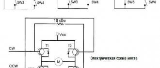
Speed control of asynchronous motors
To regulate the rotation speed of asynchronous electric motors and control their operating modes, the following methods exist:
- Frequency - when the frequency of the current in the electrical network changes, the rotation speed of the electric motor changes. For this method, a device called a frequency converter is used;
- Rheostat - when the resistance of the rheostat in the rotor changes, the rotation speed changes. This method increases the starting torque and critical slip;
- Pulse is a control method in which a special type of voltage is supplied to the motor.
- Switching the windings during operation of the electric motor from a star circuit to a delta circuit, which reduces starting currents;
- Control by changing pole pairs for squirrel-cage rotors;
- Connecting inductive reactance for wound-rotor motors.
With the development of electronic systems, the control of various asynchronous electric motors is becoming more efficient and accurate. Such engines are used everywhere in the world, the variety of tasks performed by such mechanisms is growing every day, and the need for them is not decreasing.
The final stage: features of engine checks under load
You cannot make a conclusion about the serviceability of the electric motor by relying only on the readings of the multimeter. It is necessary to check the performance characteristics of the drive under load, when it needs to perform rated work using the applied power.
Turning the voltage on at idle and checking that the rotor begins to rotate, as some novice electricians do, is a typical mistake.
For example, the owner of a very short video of PrJSC Dunaisudoremont believes that by measuring the current in the windings, he was convinced that the repaired engine was ready for further operation.
However, such a conclusion can only be given after performing long-term work and assessing not only current values, but also measuring stator and rotor temperatures and analyzing heat removal systems.
Unidentified defects of improper assembly or damage to individual elements can repeatedly cause additional repairs with great labor costs. If you still have questions on the topic of how to check an electric motor with a multimeter, then ask them in the comments.
Stator in different types of electric motors
The stator is an integral component of an electric machine that remains stationary while the engine is running. The rotor is the rotating part of an electric motor that transmits mechanical energy to the output shaft. Another name for a rotor is an armature.
Synchronous or commutator motor
Electric current is transmitted to the commutator lamellas by graphite brushes. Such an electric motor will operate in both direct and alternating current networks. The pulsating magnetic field generated by the stator windings will interact with the pulsating magnetic field generated by the armature windings. The rotor will begin to rotate. Such electric motors are widely used in various household and industrial appliances: electric drills, vacuum cleaners, power drives of machine tools, and electric vehicles.
Interesting. Motors of this type have another name - synchronous. This means that the rotation speed of the rotor is equal to the rotation speed of the electromagnetic field arising in the motor.
Asynchronous motors
The overwhelming majority of electric motors used both in industry and in everyday life are asynchronous electric motors with squirrel-cage rotors. Such motors are used in three-phase and single-phase AC networks.
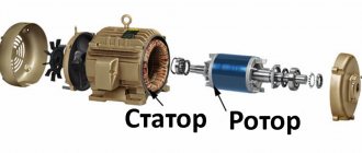
Asynchronous motor
The stator structure is assembled from a large number of steel plates and is located in a base housing cast from non-magnetic metals: cast iron or aluminum.
Stacked motor stator
Plate material – electrical steel. The plates are insulated from each other with a special dielectric varnish. The stator has longitudinal grooves where three windings are placed, shifted relative to the axis of rotation of the electric motor by 120 degrees from each other. The rotor is also made of insulated electrical steel plates. Rods made of aluminum, less often copper, are placed in the grooves of the rotor, connected at the ends by slip rings. Hence the name - squirrel-cage rotor. This design, called a “squirrel wheel,” plays the role of a rotor winding.
Below is a cross-sectional view of an asynchronous electric motor. You can clearly see what a stacked stator is.
Sectional view of an asynchronous motor
The motor windings can be connected to a three-phase electrical network in a delta or star configuration.
Three-phase motor connection options
The circuit is switched in the motor terminal box, called born or brno.
When three-phase voltage is applied, pulsating currents arise in the stator windings, which cause the appearance of a rotating magnetic field in the stator. This field crosses the conductive rods of the rotor, in which secondary pulsating currents are induced. The result is the appearance of a magnetic field in the rotor. The magnetic fields of the stator and rotor interact and cause the rods of the “squirrel wheel” to rotate, along with the rotor itself. The armature rotates at a speed slightly lower than the magnetic field of the stator.
The magnitude of this difference is called slip and can range from 2 to 8%. Due to the presence of slip, motors of this design are called asynchronous. The sliding effect is physically necessary for the operation of an asynchronous motor - there will be no lag in the rotation of the rotor from the magnetic field of the stator, no current will be induced in the rotor rods, and the magnetic field in the armature causing the rotor to rotate will disappear.
What is a rotor
A rotor, also sometimes called an anchor, is a moving, that is, rotating part in a generator or electric motors, which are widely used in household and industrial appliances.
If we consider the rotor of a DC motor or a universal commutator motor, then it consists of several main components, namely:
- Core. It is made of many stamped thin metal plates, insulated from each other by a special dielectric or simply an oxide film, which conducts current much worse than pure metal. The core is made up of them and is a “layer cake”. As a result, electrons do not have time to accelerate due to the small thickness of the metal, and the heating of the rotor is much less, and the efficiency of the entire device is higher due to reduced losses. This design solution was made to reduce Foucault eddy currents, which inevitably arise during engine operation due to magnetization reversal of the core. The same method of dealing with them is used in AC transformers.
- Windings Copper wire, coated with varnish insulation, is wound around the core in a special way to prevent the occurrence of short-circuited turns, which are unacceptable. The entire winding is additionally impregnated with epoxy resin or varnish to fix the windings so that they are not damaged by vibrations from rotation.
- The rotor windings can be connected to a commutator - a special block with contacts securely fixed to the shaft. These contacts are called lamellas, they are made of copper or its alloy for better transmission of electrical current. Brushes, usually made of graphite, slide along it, and at the right moment electric current is supplied to the windings. This is called sliding contact.
- The shaft itself is a metal rod, at its ends there are seats for rolling bearings; it may have threads or recesses, grooves for a key for attaching gears, pulleys or other parts driven by an electric motor.
- A fan impeller is also placed on the shaft so that the engine cools itself and does not have to install an additional device for heat removal.
It is worth noting that not every rotor has windings, which, in essence, are an electromagnet. Instead, permanent magnets can be used, as in brushless DC motors. But an asynchronous motor with a squirrel-cage rotor does not have windings in the usual form; instead, squirrel-cage metal rods are used, but more on that below.
Operating principle of electric motors
Induction motors consist of a rotor and a stator.
The currents in the stator windings are created by the phase voltage, which drives the induction motor. These currents create a rotating magnetic field, also called a stator field. The rotating magnetic field of the stator is determined by the currents in the windings and the number of phase windings.
A rotating magnetic field forms a magnetic flux. The rotating magnetic field is proportional to the electric voltage, and the magnetic flux is proportional to the electric current.
The rotating magnetic field of the stator moves faster than the rotor, which promotes the induction of currents in the windings of the rotor conductors, resulting in the formation of a rotor magnetic field. The magnetic fields of the stator and rotor form their own fluxes, these fluxes will attract each other and create a torque that causes the rotor to rotate. The operating principles of an induction motor are shown in the illustrations on the right.
Thus, the rotor and stator are the most important components of an AC induction motor. They are designed using CAD (Computer Aided Design). Next we will talk in more detail about the design of the rotor and stator.
Difference from synchronous motor
Along with simple asynchronous electrical machines, synchronous units are also used in industry. The main difference between a synchronous motor is the presence of an auxiliary winding on the rotor, designed to create a constant magnetic flux, as shown in Figure 4 below.
Rice. 4. Difference between an asynchronous and a synchronous electric motor
This winding creates a magnetic flux that is independent of the presence of electromotive force in the stator windings of the electric motor. Therefore, when a synchronous electric motor is excited, its shaft begins to rotate simultaneously with the stator field. Unlike the asynchronous type, where there is a difference in movement, which is physically expressed as sliding and is calculated by the formula:
It will be interesting➡ Resistivity for common materials
s = (n1 - n2) / n1
where s is the slip value, measured as a percentage, n1 is the frequency with which the stator field rotates, n2 is the frequency with which the rotor rotates.
Synchronous electric motors are used in those devices where it is important to maintain high precision in the synchronization of power supply and the start of movement. They also ensure that performance characteristics are maintained at the time of start-up.
Single-phase asynchronous electric motors
Device and principle of operation
The power of such a single-phase 220V motor can, depending on the design, range from 5 W to 10 kW. Its rotor is usually a short-circuited winding (“squirrel cage”) - copper or aluminum rods closed at the ends.
Such a single-phase motor usually has two windings offset by 90° relative to each other. The working (main) one occupies most of the stator slots, and the starting (auxiliary) one occupies the remaining part. And it is called single-phase because it has only one working winding.
Alternating current flowing through the main winding creates a periodically changing magnetic field. It can be considered to consist of two circular ones with the same amplitude, rotating towards each other.
According to the law of electromagnetic induction, in closed turns of the rotor, a changing magnetic flux creates an induced current that interacts with the field that generates it. If the rotor is stationary, the moments of the forces acting on it are the same, as a result of which the rotor remains stationary.
If the rotor begins to rotate, then the equality of the moments of these forces will be violated, since the sliding of its turns relative to the rotating magnetic fields will become different. As a consequence, the Ampere force acting on the rotor turns from the direct magnetic field will be significantly greater than from the reverse one.
An induced current in the rotor turns can only arise when they cross the magnetic field lines. And to do this, they must rotate at a speed slightly lower than the field rotation frequency (with one pair of poles - 3000 rpm). Hence the name that such electric motors received, asynchronous.
As the mechanical load increases, the rotation speed decreases and the magnitude of the induction current in the rotor turns increases. As a result, both the mechanical power of the engine and the power of the alternating current it consumes increase.
Startup and connection diagram
It is clear that it is inconvenient to manually spin the rotor every time you start the electric motor. The starting winding is used to create the initial starting torque. Since it makes a right angle with the working winding, in order to create a rotating magnetic field, the current in it must be shifted in phase relative to the current in the working winding by also 90°.
This can be achieved by including a phase-shifting element in its power supply circuit. A resistor or inductor cannot provide a phase shift of 90°, so in most situations it is logical to use a capacitor as a phase-shifting element. In this case, a single-phase electric motor has the best starting properties.
When the phase-shifting element is a capacitor, single-phase electric motors can be structurally as follows:
- with a starting capacitor (Fig. a);
- with starting and working (Fig. b);
- only with a working capacitor (Fig. c).
The first (most common) option involves connecting the starting winding with a capacitor for a short time during the start-up, after which they are turned off. It can be implemented using a time relay, or even simply by closing the circuit while pressing the start button. This starting circuit is characterized by a relatively small starting current, but in rated mode the characteristics are low. The reason is that the stator field is elliptical (it is stronger in the pole direction than in the perpendicular direction).
A circuit with a working, always-on capacitor works better in nominal mode, but has mediocre starting characteristics. The option with a starting and running capacitor is intermediate between the two described above. Calculating the values of their capacitances is relatively simple: for the working one 0.75 μF per 1 kW of power, for the starting one - 2.5 times more.
What elements does the stator of a synchronous generator consist of and the principle of operation?
Stator elements:
- Package of stator windings;
- Stator core or package;
- Wires for connection output.
The stator itself is made of three windings, three different current values are formed in them, this circuit is a three-phase output. The ends of each winding extend from the generator body (they are connected to it), the second end is connected to the rectifier. To concentrate and enhance the magnetic field in the generator, a core made of metal plates is used.
The stator winding of a synchronous generator is located in special slots, usually there are 36 such slots. In each slot, the winding is held by a wedge. This wedge is made of insulating materials.
Stator and rotor in asynchronous motors
Three-phase asynchronous motors have their own characteristics; the rotor and stator in them differ from those used in other types of electric motors. For example, the rotor can have two designs: squirrel-cage and phase. Let us consider the structural features of each of them in more detail. However, first, let's briefly understand how an induction motor works.
A rotating magnetic field is created in the stator. It induces an induced current on the rotor and thereby sets it in motion. Thus, the rotor always tries to “catch up” with the rotating magnetic field.
It is also necessary to mention such an important feature of an asynchronous motor as rotor slip. This phenomenon lies in the difference between the rotor speed and the magnetic field created by the stator
This is explained precisely by the fact that current is induced in the rotor only when it moves relative to the magnetic field. And if the rotation speeds were the same, then this movement simply would not occur. As a result, the rotor tries to “catch up” with the magnetic field in speed, and if this happens, then the current in the windings ceases to be induced and the rotor slows down. At this moment, the force acting on him grows, he begins to accelerate again. This is how the effect of stabilizing the rotation speed is obtained, for which these electric motors are in great demand.
Squirrel cage rotor
It is also a structure consisting of metal plates that act as a core. However, instead of a copper winding, there are rods or rods installed there that do not touch each other and are short-circuited with metal plates at the ends. In this case, the rods are not perpendicular to the plates, but are directed at an angle. This is done to reduce magnetic field and torque pulsations. In this way, short-circuited turns are obtained, hence the name.
Slip rotor
The main difference between a wound rotor and a squirrel-cage rotor is the presence of a three-phase winding, laid in the grooves of the core and connected in a special collector with three rings instead of lamellas. These windings are usually connected in a star. Such electric motors are more labor-intensive to manufacture due to the complexity of the design, but their starting currents are lower than those of squirrel-cage motors, and they are also better adjustable.
We hope that after reading this article you no longer have any questions about what the rotor and stator of an electric motor are and what their operating principle is. Finally, we recommend watching a video that clearly discusses this issue:
How to check the stator winding of an angle grinder at home in different ways
There are a large number of different electrical devices that can be used to diagnose the stator. However, at home, a limited number of technical means are used.
In the following video, a multimeter, or more commonly called a tester, is used as a tool for diagnosing the rotor and stator of an electric drive. Used to measure various electrical parameters: resistance, current, voltage. To determine faults in the form of broken wires or breakdown of the winding on the housing, the “ohmmeter” mode is used, that is, a certain resistance value is set, which is comparable to that present in the circuit being tested. In this case, with a limit of 200 Ohms.
A breakdown of the stator to the housing is determined by applying indicator probes to its housing and one of the ends of the winding. The presence of any resistance value on the indicator indicates the presence of a defect in the form of a breakdown of the winding to the housing. When diagnosing a winding break, the device indicator will not show anything when the probes are aligned with the winding terminals.
More complex manipulations should be carried out when checking the rotor windings of an electric drive. A winding break can occur in any connection with a single commutator lamella. Therefore, it is necessary to check the resistance between all lamellas of the collector by applying indicator probes to them one by one. In the absence of a break, the resistance will have the same small value in all cases. Any deviations indicate the presence of a break. Breakdown of the winding to the housing is checked with probes when they come into contact with the commutator and the “iron” from a set of electrical steel sheets. The indicator scale should not react to this action.
However, it is impossible to determine the turn-to-turn short circuit with a multimeter. A device called a short-circuited turn indicator (SCI) is used here. More details about it in the information below.
The operating principle of the device for determining interturn short circuits is shown in the following video. The device induces a magnetic field in the winding being tested. If there are short-circuited turns in the winding, the short circuit current causes increased resistance to the electromagnetic field generated by the device. By adjusting the IKZ, a setting is made, upon reaching which a light signal is triggered (the indicator light changes color from green to red) or a sound is heard. In addition to the main application, the author shows a method for determining where the winding wires are connected to the commutator lamellas, in the absence of visually visible contacts.
In one of the Makita models in the following video, smoke began to appear during operation, which is a sure sign of a burnt out rotor or stator. To determine the reasons, the author performed a complete disassembly of the angle grinder, which made it possible to perform a good external inspection of the components of the angle grinder suspected of malfunctioning. While no signs of smoke damage were found on the rotor, several places of burnt electrical insulating varnish were clearly visible on the stator.
Important: after a visual inspection, it is necessary to once again check with instruments the unit on which no external defects were found. So, for example, in this case, a multimeter detected breaks in the winding on the rotor. By the way, an external inspection of the stator was sufficient, since the multimeter could not detect a defect in the form of an interturn short circuit.
The multimeter, which is presented in the following video, is easy to use and allows you to take readings without unnecessary fuss, when the measured values “jump” in a device that does not have this option. A method for determining the measurement error associated with the resistance of indicator probes is shown. The approximate value of the winding resistance where there are no faults is given.
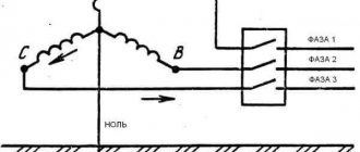
Connecting an asynchronous motor
Three-phase alternating current
The three-phase alternating current electrical network is the most widely used among electrical energy transmission systems. The main thing in comparison with single-phase and two-phase systems is its efficiency. In a three-phase circuit, energy is transmitted through three wires, and the currents flowing in different wires are phase-shifted relative to each other by 120°, while the sinusoidal EMFs at different phases have the same frequency and amplitude.
Three-phase current (phase difference 120°)
Star and triangle
The three-phase stator winding of the electric motor is connected according to the circuit depending on the mains supply voltage. The ends of a three-phase winding can be: connected inside the electric motor (three wires come out of the motor), brought out (six wires come out), brought into a distribution box (six wires come out of the box, three wires come out of the box).
Phase voltage - potential difference between the beginning and end of one phase
Another definition for a star connection: phase voltage is the potential difference between the line wire and the neutral (note that the delta connection does not have a neutral)
Line voltage
- potential difference between two linear wires (between phases).
| Star | Triangle | Designation |
| Uл, Uф - linear and phase voltage, V, | ||
| Il, Iph - linear and phase current, A, | ||
| S — total power, W | ||
| P—active power, W |
Attention: Although the power for star and delta connections is calculated using the same formula, connecting the same electric motor in different ways to the same electrical network will result in different power consumption. In this case, incorrect connection of the electric motor can lead to melting of the stator windings.
Example: Let’s say the electric motor was connected in a star configuration to a three-phase alternating current network Ul=380 V (respectively Uph=220 V) and consumed current Il=1 A
Total power consumption:
S = 1.73∙380∙1 = 658 W.
Now let’s change the connection diagram to a “triangle”, the linear voltage will remain the same Uл=380 V, and the phase voltage will increase by the root of 3 times Uф=Uл=380 V. An increase in the phase voltage will lead to an increase in the phase current by the root of 3 times. Thus, the linear current of the delta circuit will be three times greater than the linear current of the star circuit. And therefore the power consumption will be 3 times greater:
S = 1.73∙380∙3 = 1975 W.
Thus, if the motor is designed to be connected to a three-phase AC network in a star configuration, connecting this electric motor in a delta configuration may lead to its failure.
If in normal mode the electric motor is connected in a delta circuit, then to reduce the starting currents during the start-up it can be connected in a star circuit. In this case, along with the starting current, the starting torque will also decrease.
Connecting an electric motor according to a star and delta circuit
Designation of the stator terminals of a three-phase electric motor
Designation of the terminals of the stator windings of newly developed
three-phase machines according to
GOST 26772-85
| Winding connection diagram, name of phase and output | Pin designation | |
| Start | End | |
| Open circuit (number of pins 6) | ||
| first phase | U1 | U2 |
| second phase | V1 | V2 |
| third phase | W1 | W2 |
| Star connection (number of pins 3 or 4) | ||
| first phase | U | |
| second phase | V | |
| third phase | W | |
| star point (zero point) | N | |
| Delta connection (number of pins 3) | ||
| first conclusion | U | |
| second conclusion | V | |
| third conclusion | W |
previously developed stator winding terminals
and modernized three-phase machines in accordance with
GOST 26772-85
| Winding connection diagram, name of phase and output | Pin designation | |
| Start | End | |
| Open circuit (number of pins 6) | ||
| first phase | C1 | C4 |
| second phase | C2 | C5 |
| third phase | C3 | C6 |
| Star connection (number of pins 3 or 4) | ||
| first phase | C1 | |
| second phase | C2 | |
| third phase | C3 | |
| zero point | ||
| Delta connection (number of pins 3) | ||
| first conclusion | C1 | |
| second conclusion | C2 | |
| third conclusion | C3 |
Types of generator stator windings
There are several different types of stator lead connections; Before you start checking or looking for a stator replacement, it is important to know what type of stator you are working with. All stators have 3 phases, but they can have different connection types:
| Connection of stator terminals "delta" Connection of stator "delta" has: 6 stator terminals, which are connected in pairs to each other (the beginning of one winding to the end of the next) when connected to a diode bridge | Winding the stator with double wire |
| Star connection of stator terminals | Combined terminal connection: star and delta at the same time |
| The star-connected stator has An alternator with a star stator connection begins charging at a lower RPM and has a lower maximum power than an alternator with a delta connection stator. An alternator with a delta-connected stator starts charging at a higher RPM and has a higher maximum power than an alternator with a star-connected stator. Some alternators with a star stator connection have an additional 2 power diodes connected to the midpoint of the winding. This increases the generator's maximum output current by approximately 10% and with this addition, the generator not only starts charging at a lower RPM, but also achieves a higher maximum output. Once the stator connections are known, you can check this by measuring the resistance of each phase (they should be equal). The stator must be checked for a short circuit to the body of the stator winding (insulation resistance >1MOm). This check must be done with the stator disconnected from the diode bridge. |
Motors used in industry
Both types of motors are successfully used in industry: asynchronous with a squirrel-cage rotor, and synchronous commutator.
The first type of device has important advantages:
- Low price;
- Reliability and durability;
- Easy to use.
There are also disadvantages:
- Impossibility of smooth control of armature speed;
- Low rotation speed - limit 3000 rpm. in networks with a frequency of 50Hz;
- Large starting currents.
However, the advantages of these products far outweigh their disadvantages.
For your information. Asynchronous motors are used in those devices that require constant operating modes of industrial or transport equipment. For example, in drives of various pumps, belt conveyors, in ventilation systems, in lifting mechanisms. The niche of asynchronous electric machines occupies 65-75% of the total volume of electric motors used.
Synchronous commutator motors have their advantages:
- Possibility of smooth, stepless change of rotation speed;
- Great power;
- High rotation speed.
Disadvantages inherent in commutator electric motors:
- Relatively high cost;
- Sliding contacts of the armature commutator, reducing operational reliability and reducing the service life of the machine;
- Frequent maintenance required.
They are used where a smooth change in angular speeds is necessary: these are machine tool drives, traction motors of electric vehicles, and precision installation systems.
Both types of engines are widely used in industry and everyday life. For their long-term and trouble-free operation, it is necessary to carry out routine maintenance, and, if necessary, restoration repairs, including rewinding the stator and rotor windings.
Stator rewinding technology
Indicators of abnormal operation of the electric motor are:
- Power reduction;
- Increased heating of the case;
- “Breaking through” voltage to ground.
In this case, you should diagnose the stator malfunction. It is necessary to determine how to check the stator for an interturn short circuit with a multimeter. The winding resistance value is indicated in the reference literature for a specific motor. By checking the resistance of each winding with a multimeter, you can determine which one is defective. After which it is necessary to rewind one or all stator windings.
Basic operations:
- Removing old windings from the stator slots;
- Cleaning the grooves from the remains of old electrical and thermal insulation;
- Installation of new insulation in the stator slots;
- Laying new windings;
- Impregnation of windings with dielectric varnish and drying it;
- Checking the electrical parameters of new stator windings.
If repairs are carried out correctly, the electric motor will restore its original characteristics.
Features of the design of each element
The stator of an asynchronous electric motor is a cylinder made of sheets of special electrical steel up to 0.5 mm thick, coated with varnish. This cylinder is the core; on the inside there are grooves where the windings are placed. In three-phase ones, respectively, shifted by 120 degrees, in single-phase ones - by 90. The windings can be laid in several ways, depending on their connection diagram and operational requirements. It is on this that indicators such as torque and power on the shaft depend. And if there are more than 2 pairs of poles, it can be used in servo control systems for drive mechanisms.
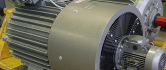
The stator is pressed into the housing or located between the flanges. The body and side covers are made of cast iron or aluminum alloy. They have fins to increase the area and increase the efficiency of heat dissipation during operation. This device allows for better engine cooling, ensuring prolonged operation under extreme loads.
The single-pole winding of such an electric motor is wound from 3 coils . Each of them is called a phase. To achieve the required operating parameters of the motor, the winding is placed in opposite slots of the core. The coils are connected to each other in a special way in accordance with the connection diagram and expected characteristics, providing excitation of the magnetic field and the required torque during rotation.
All ends of the sensors are brought out into the terminal box, which allows them to be connected in a star or triangle, which depends on the connection diagram of the control system and the power supply. The 3-phase electric motor is universal; if necessary, it can be connected to single-phase power supply with linear voltage. When the windings are connected in a triangle, the winding voltage is equal to linear Uph, and when connected according to a star circuit – √3Uph.
Scope of application of electric motors with wound rotor
Due to their high torque, low starting currents and the ability to operate for a long time at high loads, motors with a wound rotor are used where high electric motor power is needed, but there is no need to smoothly regulate the rotation speed over wide ranges. In addition, these machines are perfectly suited for starting with a load on the shaft.
Due to their high performance, wound rotor motors are most often used on various serious, heavy power equipment, for example, cranes, elevator drives, machine tools, and various lifts. In other words, these engines are used where there is a need to start under load, and not at idle.
Checking a wound rotor motor
To check the stator windings of a three-phase IM for integrity, you need to get to their connection terminals. Then you need to measure the resistance between the phase terminals separately, having first removed the jumpers. If the resistance of any winding is less than that of others, this indicates a short circuit between its turns. In this case, the motor is rewinded.
To check the rotor windings, you need to find the leads from the slip rings. Then you need to make sure that the winding resistances match. If the design of the electric motor provides for a system for disconnecting the rotor windings, the lack of contact may be due to the breakdown of this mechanism, and not to the breakage of the turns.
The following factors may indicate the presence of any malfunction of the blood pressure:
- Reduced rotation speed under load. Characteristic of high resistance in the rotor circuit, weak contact in its winding, low mains voltage
- Deployment of the IM when the rotor circuit is open - short circuit in the rotor winding
- Excessive uniform increase in engine temperature - prolonged overload of the motor or its insufficient cooling
- Heating of the stator winding of a local nature - double short circuit of the stator coils to the housing or between phases, short circuit between turns, incorrect connection of coils in phase with each other
- Heating of the stator steel of a local nature - violation of the insulation between the steel sheets, their melting and burnout, short circuit
- Extraneous noise during AD operation. It can be caused by both bearing failure and insufficient pressing of active steel. Determined by ear by the nature of extraneous noise
- Burnout in the armature winding of the fuses, lack of contact in the supply wiring, failure of the rheostat
For self-diagnosis and correction of electric motor malfunctions, at least minimal knowledge of the design of blood pressure and electrical circuits in general is necessary. However, it is highly not recommended to repair an electric motor with a wound rotor yourself, as this can lead to electric shock.
An asynchronous motor is an alternating current motor whose rotation speed is not equal to the frequency of the voltage in the stator windings. These electric motors are widely used because they are quite durable. Asynchronous single-phase and three-phase motors can operate under significant load for a long time without overheating and maintain their torque. The operation of an asynchronous motor is simple, but its characteristics directly depend on the parameters of the windings and the technology of their installation.
Types of motors
Based on the type of supply network, asynchronous electric motors are divided into:
- Three-phase. The windings of asynchronous motors of this type consist of 3 coils, specially laid in the stator slots. They are designed for use in industry, as they have high efficiency and cosφ close to 1, and to ensure additional savings they work with an energy recovery system during braking, acting as a generator.
- Single-phase asynchronous motor. It is used in everyday life and industry: old washing machines, household fans, refrigeration and other types of equipment. They have lower efficiency and power compared to three-phase ones, which is explained by losses in the stator due to the lack of an additional phase.
Principle of operation
The operating principle of an asynchronous motor is quite simple. It is based on two physical phenomena:
- When voltage is applied to the stator windings, a rotating magnetic field appears in the motor.
- The field affects the current induced in the rotor. And this creates a torque that turns the motor shaft relative to the poles.
For each rotation of the shaft, the poles change polarity with the network frequency. Therefore, the voltage of the stator winding has a standard frequency, and the rotation speed depends on:
- shaft loads;
- number of pole pairs;
- features of stator winding.