What is the difference between synchronous and asynchronous motor?
The motor is called asynchronous because the rotation frequency of the stator magnetic field does not coincide with the rotation frequency of the rotor. ... In a synchronous motor, the rotation frequency of the stator magnetic field and the rotor rotation frequency are the same.
Interesting materials:
When is Oge in 2022? When is Easter in 21 what date? When are crosses baked in 2022? When do they change the time in Russia in 2022? When will the Ob River go to Surgut in 2022? When is Easter celebrated in 2021? When is forgiveness day in 2022? When is winter farewell in 2021? When is Radonitsa for Catholics in 2022? When is Radonitsa celebrated by the Orthodox in 2022?
Rotor and stator
The easiest way to understand the concepts of rotor and stator. Because their physical condition determines their name. In other words, the terms rotor and stator refer to parts of electrical machines with respect to the physical movement of these parts relative to each other. In addition, each of these terms always refers to the same specific and unchanging part of the electric machine. It’s a little more difficult to understand what an armature and an inductor are. Since they can mean completely different parts of machines in different conditions.
Presumably the word stator comes from the Latin sto - standing. And already from Latin the English stator was formed. That is, the stator is a stationary (static) part of an electric generator or electric motor. In order for an electric machine to do any work, the stator must interact with the rotor. This interaction occurs through electromagnetic induction.
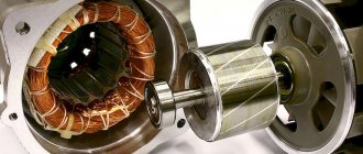
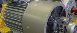
Stator and rotor of an asynchronous electric motor
The word rotor probably comes from the Latin rota - wheel, roto - spinning. That is, the rotor represents the moving (usually rotating) part of an electrical machine. The rotor is made mainly in the form of a cylinder or disk. By design, the rotor is connected to some kind of shaft. Through this shaft, it is either driven (generator) or itself drives a machine (electric motor).
What is a stator
The stator is the stationary part in an electric motor. Usually it is combined with the device body and is a cylindrical part. It also consists of many plates to reduce heating due to Foucault currents, which are necessarily varnished. At the ends there are seats for sliding or rolling bearings.
The design is called a stator package; it is pressed into the cast iron body of the device. Inside this cylinder, grooves are machined for the windings, which, just like for the rotor, are impregnated with special compounds so that the heat is distributed more evenly throughout the device and the windings do not rub against each other due to vibration.
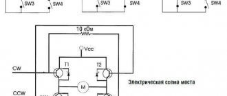
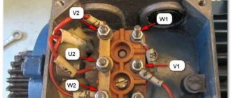
The stator windings can be connected in different ways depending on the purpose and type of electrical machine. For three-phase electric motors, star and delta connection types are applicable. They are presented in the diagram:
To make connections, a special distribution box (“boron”) is provided on the device body. The beginnings and ends of three windings are brought into this box and special terminal blocks of various designs are provided, depending on the power and purpose of the machine.
There are serious differences in the operation of motors with different winding connections. For example, when connected with a star, the engine will start smoother, but it will not be possible to develop maximum power. When connected in a triangle, the electric motor will produce all the torque declared by the manufacturer, but the starting currents in this case reach high values. The power grid may simply not be designed to handle such loads. Using the device in this mode is fraught with heating of the wires, and in a weak place (these are junctions and connectors), the wire can burn out and lead to a fire. The main advantage of asynchronous motors is the convenience of changing the direction of their rotation; you just need to swap the connections of any two windings.
Starter armature: the heart of the electric engine starting system
» Articles » Starter anchor: the heart of the electric engine start system
Every car has a special unit for starting the engine - a starter. An important component of the starter is the armature - the rotor of the electric motor, the torque of which ensures the start of the motor. Read the article about what a starter armature is, how it works and works, as well as its maintenance and repair.
Anchor
The electrical engineering term armature usually refers to one of the parts of electrical machines that have windings. However, this term may also refer to the moving part of the magnetic circuit of a relay or electromagnet. In electric machines, the armature can be either a stator or a rotor. It all depends on the circumstances. GOST 27471-87 (Rotating electric machines. Definitions) gives the armature this designation
The part of a DC commutator machine or an AC synchronous machine in which an emf is induced and a load current flows.
Typically, in practice, the concept of armature refers to the part of the electric motor through the windings of which the electric current of the network flows during operation. That is, the armature is that part of the electric motor to the windings of which power is connected (working winding). For a generator, the armature means that part from which the generated voltage is removed. For example, in a brushed DC motor the armature is the rotor. And in a brushless DC motor, the armature will be the stator. For synchronous alternating current generators, most often the armature is the stator. Although in some low-power generators, the armature is a rotor from which the generated voltage is removed through brushes.
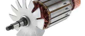
DC motor armature
An example of an armature is most rotors from motors for inexpensive hand-held power tools. Because in such tools the electric motors are commutator. That is, there is a collector on the rotor, to which voltage is supplied using graphite brushes. In other words, all rotors with commutators are armatures. However, the commutator should not be confused with the slip or slip rings located on the rotor of some electric machines. Slip rings have a continuous, uniform circle arrangement. The collector consists of many plates - lamellas, isolated from each other.
What is an ED stator and its purpose?
The stator is the stationary part of the engine that works in tandem with the rotor. The stator consists of a base and a core. The base is a solid body made of aluminum or cast iron alloys. The core is made of sheet electrical steel, the thickness of which depends on the characteristics of the motor and ranges from 0.35 to 0.5 mm. The stator has slots designed to accommodate the windings. The winding is wires twisted together and connected in a parallel manner, which makes it possible to reduce the eddy currents that arise during operation. Three-phase rewinding of the stator creates an electromagnetic field. A certain number of coils are installed in the grooves, which are connected to each other.
In the event of a motor failure, the stator is rewinded. Rewinding options depend on the type of insulation. Insulation is selected depending on the maximum voltage, rewinding temperature, slot type and winding type.
The material used for winding is copper wire. Rewinding is carried out in one or two layers, depending on the location of the coils in the grooves.
ED repair begins with cleaning or blowing dirt and dust out of the stator components. The next step is to disassemble the housing to replace the winding. Using mechanical tools, the front part of the stator, where the rewinding is located, is cut off.
In order to disassemble the stator, it is necessary to heat it to a temperature of 200 degrees, after which removal of the winding and coils will be easier. After the stator is disassembled, the grooves are cleaned. A new winding is installed in the cleaned and prepared grooves using ready-made templates. Installed new coils must be coated with varnish and dried at a temperature of 150 degrees for two hours.
The resistance between the housing and the winding can be checked only after the entire drying technology has been completed. The use of cables of different diameters makes it possible to adjust the operating parameters of the electric motor.
During operation of the electric motor, situations are possible when parts begin to overheat. This is due to changes in current consumption. This occurs due to an open circuit. Another reason for heating the ED is wear of the bearings. This negatively affects the performance of the insulation winding. Manufacturers install overheating protection on all types of electric motors. It monitors and triggers in the following cases:
- exceeding the starting time;
- overload;
- power surges;
- failure of phase wires;
- rotor jamming;
- failure of drive devices.
A thermal relay is also used to protect the stator. It is triggered when a bimetallic plate heats up, which, under the influence of a spring, opens the electrical circuit. The plate returns to its original position when the button is pressed.
The relay can be built into the ED, or can be purchased as a separate unit.
What is an armature in an engine?
The armature of asynchronous electric motors can often be called a rotor. And so, the rotor is the moving part of the electric motor, consisting of a cylinder, which is assembled from sheets of special steel intended for electrical devices. These sheets are put on the shaft. Rotors or armatures are either phase or short-circuited. The three-phase winding of the wound rotor is connected in a star circuit and has slip rings on the shaft. Using brushes, connect to the rings:
- chokes that hold the rotor current and stabilize the operation of the electric motor during overloads and sudden changes in speed;
- current source (DC);
- rheostat for adjusting the starting torque;
- inverter power supply, which allows you to control the shaft rotation speed and adjust the torque characteristics.
Electric motors with a wound rotor are installed on machines operating with variable loads.
The anchor practically does not wear out during operation. Only the brushes can be replaced. Basically, the armature only needs to be cleaned from carbon deposits that appear when the stator winding heats up. If the rotor alignment is disrupted due to wear of the bearings, serious breakdowns are possible, leading to the stoppage of the electric motor. To avoid unwanted equipment downtime while waiting for the ED to be replaced, preventive maintenance is carried out.
The operation of the armature is negatively affected by moisture, which leads to corrosion on the metal surface, increasing friction, leading to an increase in current load. This leads to excessive heating, melting of the contact and sparking of the electrode. Based on the appearance of sparking, we can conclude that the current collectors have outlived their service life. If the ED turns out to work, then most likely the dielectric collector brushes between the plates must be replaced. There may have been a short circuit.
You can talk about an ED malfunction if:
- the engine sparks;
- a hum is heard during operation;
- vibration appears;
- the anchor changes its direction of rotation in less than a revolution;
- the case gets very hot;
- a burning smell appears.
Seeing these irregularities in operation, it is recommended to disconnect the motor from the power supply and conduct an initial inspection, based on the results of which the fault will be determined and the engine will be sent for maintenance.
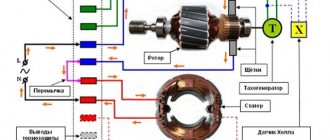
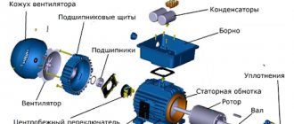
Asynchronous motor device
The design of an asynchronous motor is quite simple:
- The stator is the stationary part of the electric motor, which is equipped with field windings.
- The rotor is a rotating element of the motor that rotates under the influence of a magnetic field created by field windings located on the stator. There are 2 types of motors depending on the rotor design: squirrel-cage and phase.
- Flanges are a static part of an electric motor that contains support bearings that hold the rotor and are a kind of fastener for the stator. It is clamped between two flange covers with coupling bolts. Or they are screwed to the stator housing.
- The terminal box is a part of the static motor structure into which the ends of the windings from the stator are led out. Through it, the motor is connected to the control circuit.
- Impeller and protective casing - used to provide forced ventilation, and the casing will protect operating personnel from injury.
- Additional service windings - if necessary, together with the excitation winding on the stator, there can be an additional one designed to control and measure the operating parameters of the motor during its operation.
- Thermal sensors - industrial asynchronous motors, in addition to the windings, there are also temperature sensors that monitor overheating in case of a sharp increase in current consumption.
Read also: Weld heating registers from pipes
Also, engines can be equipped with planar gearboxes and manufactured in a single housing. These are mainly industrial types of units used on machines, conveyors and other types of equipment.
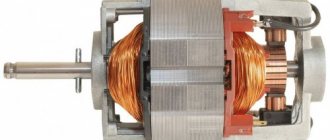
What is a rotor
A rotor, also sometimes called an anchor, is a moving, that is, rotating part in a generator or electric motors, which are widely used in household and industrial appliances.
If we consider the rotor of a DC motor or a universal commutator motor, then it consists of several main components, namely:
- Core. It is made of many stamped thin metal plates, insulated from each other by a special dielectric or simply an oxide film, which conducts current much worse than pure metal. The core is made up of them and is a “layer cake”. As a result, electrons do not have time to accelerate due to the small thickness of the metal, and the heating of the rotor is much less, and the efficiency of the entire device is higher due to reduced losses. This design solution was made to reduce Foucault eddy currents, which inevitably arise during engine operation due to magnetization reversal of the core. The same method of dealing with them is used in AC transformers.
- Windings Copper wire, coated with varnish insulation, is wound around the core in a special way to prevent the occurrence of short-circuited turns, which are unacceptable. The entire winding is additionally impregnated with epoxy resin or varnish to fix the windings so that they are not damaged by vibrations from rotation.
- The rotor windings can be connected to a commutator - a special block with contacts securely fixed to the shaft. These contacts are called lamellas, they are made of copper or its alloy for better transmission of electrical current. Brushes, usually made of graphite, slide along it, and at the right moment electric current is supplied to the windings. This is called sliding contact.
- The shaft itself is a metal rod, at its ends there are seats for rolling bearings; it may have threads or recesses, grooves for a key for attaching gears, pulleys or other parts driven by an electric motor.
- A fan impeller is also placed on the shaft so that the engine cools itself and does not have to install an additional device for heat removal.
It is worth noting that not every rotor has windings, which, in essence, are an electromagnet. Instead, permanent magnets can be used, as in brushless DC motors. But an asynchronous motor with a squirrel-cage rotor does not have windings in the usual form; instead, squirrel-cage metal rods are used, but more on that below.