Winding of phase rotors
The winding of phase rotors is carried out using loose and rod ones. Random windings are loop three-phase two-layer equal-coil windings with a shortened pitch, similar to stator random windings. The winding connection is a star. Random-wound rotors are typically designed to have a line-to-line voltage of approximately 380 V.
The advantages of random windings on the rotor include: increasing the rotor voltage to the stator voltage and a corresponding decrease in the rotor current, and therefore reducing the size of the contact-brush assembly, improving the operation of the starting and control equipment; the possibility of reducing the number of rotor slots and a corresponding reduction in the consumption of insulating materials; the possibility of mechanizing the laying of the wound rotor winding.
Random windings of phase rotors
used for motors with power up to 50 kW. The grooves are usually trapezoidal or pear-shaped, semi-closed, as shown in Fig. 10, a, b.
The core windings of phase rotors are two-layer wave windings. They are formed by rods of rectangular copper wire placed in rectangular semi-closed grooves of the rotor. Two rods are placed in each groove (Fig. 10, c), pre-insulated.
Rice. 10. Grooves of phase rotors
of the phase rotor winding coils
are divided into loop and wave. In the loop winding (Fig. 11), loop-shaped movements occur, and in the wave winding (Fig. 12), wave-shaped movements occur as each phase is bypassed. The stator windings of motors with voltages up to 0.66 kV for general industrial use are made only as loop windings. In the frontal parts the rods are bent (Fig. 12) so that two rods form a wave winding section. The pitch of the winding on the side of the slip rings (from the side of the winding terminals) is called the front unit or y1, and on the opposite side - the rear one y3 or y2. The sum y1+y2 is double pole division 2τ. An example of such a winding is shown in Fig. 12, where y1=y2=9, y1+y2=18, 2τ = 18.
Rice. 11. Detailed diagram of a two-layer loop winding: z1=48; 2р=8; y1=5; τ=6; β=5/6
With an integer number of slots per pole and phase, first perform q rounds in one direction, connect the two lower rods (jumper in Fig. 12) and make q rounds in the opposite direction. This creates each rotor phase winding.
Rice. 12. Detailed diagram of a two-layer wave winding: z2=36; 2р=4; y1=y2=9; τ=9
Recently, wave winding of phase rotors
, which does not require special jumpers for intermediate connections when performing a bypass rotation, as was the case in the previous case. Rotation is carried out for each phase winding using an oblique rod that passes from one layer of the groove to another. Some field distortion in this case does not have a significant effect on the operation of the asynchronous motor.
Rod windings are used for medium and high power motors with a voltage on the slip rings of 250-500 V. These windings are more labor-intensive to manufacture than random windings, due to the presence of a large number of solders and a large amount of manual work.
Contents Previous § Next3-14. LONG WINDING
The insulation of the stator slot and pressure washers is shown in Fig. 3-22 and 3-23. After laying all the conductors through the groove slot, the edges of the box, protruding outward from the groove to protect the conductor from damage during installation, are cut with a knife flush with the stator bore and bent (Fig. 3-22.6).
Groove insulation (box) for normal machines with class A insulation is made of two layers, electrical cardboard 0.1-0.3 mm thick,
glued together with insulating varnish, with varnished fabric 0.1-0.2 mm thick laid between them
.
For voltages up to 24
V,
the box consists of one layer of electrical cardboard with a thickness of 0.2-0.3
mm.
The length of the varnished fabric should be taken 15-20
mm
longer than the length of the electric cardboard, for
in order to be able to wrap la-cotton fabric on electric cardboard, as shown in Fig. 3-24. This design increases the moisture resistance of the insulation, preventing its resistance from decreasing under the influence of moisture.
The use of film-coelectric cardboard for the manufacture of a box (Chapter 2) makes it possible to reduce the thickness of the groove insulation, and replacing the inner layer of the cardboard with a synthetic film (lavsan) can significantly increase the mechanical strength of the groove insulation and raise its heat resistance to class E. For machines with increased moisture resistance, and also for machines with insulation classes B, F, H, the groove insulation is made of fiberglass and micanite.
Groove insulation, as indicated in Chap. 2, must protrude from the steel to a certain length, the so-called “overhang” (Fig. 3-24).
The place where the box exits the groove is an extremely important part of the insulation, preventing damage to the winding insulation when the teeth fluff up. To strengthen this part of the insulation in some designs, electrical
Rice. 3-22. Laying loose winding in grooves.
Rice. 3-23. Pressure washer insulation.
Russian machines provide for the widening of the groove from the edge of the core with the insertion of a U-shaped bracket made of electrical cardboard (Fig. 3-23). The insulation of the outer active steel sheets and the insulation of the washer also play an important role.
The protruding part of the box can rest on the insulation of the pressure washer, as shown in Fig. 3-23.
Rice. 3-24, Strengthening the insulation of the projection with single (a) and double (b) folding of the varnished fabric.
Another method of supporting protruding insulation is shown in Fig. 3-25, where disks made of impregnated textolite with open grooves according to the number of stator grooves are inserted on both sides of the stator package. The outer sheets of the
Rice. 3-25. Ejection support with insulating discs.
The stator is usually insulated with a sheet of electrical cardboard, placed when pressing the package.
For laying, coils (sections) are prepared, wound on a template.
To reduce the number of solders and connections on the stator, the number of coils per pole group is wound on the template at once, and with the number of poles,
equal to 2 - for the entire phase. The coils wound on the template are tied with tape and are not further insulated. An insulating stocking is put on the output ends. The dimensions of the template during repair are determined by the dimensions of the old section, and due to the softness of the section, not so much the shape of the frontal part must be precisely maintained as the length of the coil. Therefore, for most
Rice. 3-26. Universal template. 1—
plate;
2—studs; 3 -
roller (made of wood, fiber, metal).
For different machines, a universal template can be used (Fig. 3-26).
If the wire of a section has a large cross-section, then giving the section the desired shape when winding templates or when laying it becomes difficult. In this case, the section is wound on boat-shaped templates, followed by stretching (see below).
Before laying, sections of wire with fibrous insulation wound on a template are impregnated with varnish to increase moisture resistance and glue the insulation of the turns. Laying should be done in sections that have not yet dried, since dried varnish forms burrs and deprives the section of elasticity. The final drying of the winding is carried out after completion of the repair.
The laying of sections with a two-layer winding begins with laying the lower sides into the grooves corresponding to the pitch of the section. If, for example, with 12 slots on the stator, the section pitch is 6 (1-7), then the lower ones are laid first
steel armor sections in grooves 1, 2, 3, 4, 5,
6. The second sides of these sections remain raised, since they will be upper in the grooves corresponding to the step and can be laid only after laying the entire winding, i.e., last.
The section, the lower side of which will be placed in groove 7, with its upper side falls into groove 1,
in which the lower side is already laid. Therefore, this section and those following it can be laid entirely (both sides) with the groove insulation bent and wedged (Fig. 3-22.6).
If it is necessary to replace one coil during repairs, it is necessary to lift all the coils according to the step of this section.
When laying, the frontal parts of the coils of different phases are separated from one another by varnished cloth spacers.
To prevent the wires placed in the groove from crossing, they are moved apart with a fiber plate that is passed along the groove. A spacer is placed in the groove between the bottom and top sides of the coils.
The gasket should be slightly wider than the groove and have an arcuate bend, which, after laying the upper side of the section and straightening the gasket, ensures reliable separation of the layers. After laying all the wires, the edges of the box are bent, a gasket is placed on top and a wedge is driven into the groove (Fig. 3-22.6).
When performing winding work, you should use the tool shown in Fig. 3-27, ensuring good quality of winding work and fast execution. Fiber plate
(Fig. 3-27, a) is used for tensioning and placing the upper sides of the sections into the groove.
Fiber tongue
according to fig. 3-27.6, the end of which is drawn along the conductors laid in the groove, serves to eliminate their crossings.
Hatchet
from fiber according to fig. 3-27,v is used for depositing wires in a groove during the winding process.
Shown in Fig. 3-27, g leather
serves to quickly trim the edges of the groove box flush with the stator steel before turning these edges and inserting the wedge.
Guide metal cage with steel liner
(Fig. 3-27, (9) makes it easier to drive the wedges into the grooves, preventing them from breaking. For this purpose, in addition
Rice. 3-27. Wrapper tool.
a—fiber plate; b—fibrous tongue; V
- hatchet;
g
- knife;
d
— device for driving in wedges;
e
—reverse wedge; ek—punch.
In addition, a metal reverse wedge
(Fig. 3-27, e), inserted from the side opposite to that driven into the groove.
Punch
according to fig. 3-27, makes it easier to pull the wedges out of the grooves.
In addition, the wrapper should have wire hooks
for pulling the tape and
tweezers
made of a steel strip with pointed edges for cleaning wire insulation.
After laying the sections before connecting them together, insulation tests
between the turns and relative to the housing (see § 8-12). Then the sections are connected (temporarily), after which the correct connection should be checked using a compass when the phase windings are powered alternately with a small current, for example from batteries. With the correct connection, a compass drawn along the circumference of the stator bore will mark by turning the arrow the required number of pairs of poles, each of which should have an equal number of slots.
With a small cross-section of wires, the connection is most easily made by welding. The stripped and twisted ends are touched with a metal electrode, and the end of the twist is touched with a carbon electrode. An electric arc melts the end of the twist into a small ball. This method gives the most reliable connection (required voltage 50-60 V,
power 500
W).
After insulating the connection points, the stator is sent for impregnation.
Small machine stators
(up to 1 ket) with a two-layer winding are wound in a way different from those described above. The first sections of the winding of these stators are laid on both sides at once, since if the second sides of the sections are left unlaid, then with small diameters of the stator bore, further laying of the winding becomes impossible. Therefore, the first sections (their number is equal to the pitch of the sections along the grooves) are laid on both sides at the bottom of the grooves. This is followed by sections, laid with one side on the bottom, and the other on top of the groove. The last sections lie on both sides at the top of the groove. Some asymmetry of this winding is practically acceptable.
Winding is performed in pre-wound sections or directly by hand.
Fig, 3-28. Winding using the “skein” method.
Single-layer winding of small stators with concentric coils, common in small single-phase motors, is often carried out using the “winding” method. This method, as can be seen from Fig. 3-28, consists in sequentially turning over and laying through the slot of the groove in parts a long coil (skein) containing the required number of turns.
Contents Previous § Next
TYPES OF ELECTRIC MOTOR WINDINGS AND METHODS OF THEIR REPRESENTATION
An important component of electric motors is its windings, in which the main work processes for energy conversion occur. The most common types of electrical machines include:
three-phase windings of alternating current machines, usually used in the stators of three-phase asynchronous and synchronous machines, as well as in the rotors of induction motors with slip rings.
single-phase stator windings of asynchronous single-phase motors with a squirrel-cage rotor.
windings of armatures of commutator machines of direct and single-phase alternating current.
squirrel-cage windings of rotors of asynchronous electric motors.
excitation windings of synchronous and commutator machines.
The field windings of synchronous and commutator machines consist, as a rule, of relatively simple pole coils. The design of short-circuited windings of the rotors of asynchronous motors is also simple. The remaining types of windings listed above are quite complex systems of insulated conductors placed in slots, connected according to special circuits that require special study.
Turn of windings:
The simplest element of a winding is a turn, which consists of two series-connected conductors placed in grooves, which are usually located under adjacent opposite poles.
The coil conductors lying in the grooves are its active sides, since it is here that the EMF is induced from the main magnetic field of the machine. The parts of the coil located outside the groove, connecting the active conductors to each other and located at the ends of the magnetic circuit, are called the frontal parts.
The conductors forming a turn can consist of several parallel wires. This is usually done to make the winding soft and make it easier to fit into the grooves.
One or more turns connected in series form a coil or winding section. If the section consists of one turn, then such a winding is called a rod winding, since in this case the conductors located in the grooves usually represent rigid rods. A winding consisting of multi-turn sections is called a coil winding.
Winding coil:
A coil, or winding section, is characterized by the number of turns wc and pitch y, i.e., the number of magnetic circuit teeth it covers. So, for example, if one side of the coil (section) lies in the first groove, and the second in the sixth, then the coil covers five teeth and its pitch is five (y = 5). The pitch, therefore, can be defined as the difference between the numbers of the grooves in which both sides of the coil are placed (y = 6 - 1 = 5).
Often in winding data and technical literature, the pitch is designated by the numbers of the grooves (starting from the first) in which the sides of the coil are laid, i.e. in this case this designation looks like this: y = 1 - 6.
The winding pitch is called diametric if it is equal to the pole division τ, i.e., the distance between the axes of adjacent opposite poles, or, what is the same, the number of grooves (teeth) per pole. In this case, y = τ = z/2p, where z is the number of slots (teeth) of the core in which the winding is located; 2p is the number of poles of the winding.
If the coil pitch is less than the diametrical pitch, then it is called shortened. Pitch shortening, characterized by the shortening coefficient ky = y / τ, is widely used in the stator windings of three-phase asynchronous electric motors, since this saves the winding wire (due to shorter end parts), makes it easier to lay the winding and improves the characteristics of the motors. The applied step shortening usually lies in the range of 0.85 - 0.66.
In a double-pole electric machine, the central angle corresponding to the pole division is 180°. Although in four-pole machines this geometric angle is 90°, in six-pole machines it is 60°, etc., it is generally accepted that between the axes of adjacent opposite poles in all cases the angle is equal to 180 electrical degrees (180 electrical degrees). In other words, pole division τ = 180 el. hail
There are single-layer windings, where each slot is occupied by the side of one coil (section), and two-layer windings, where the sides of different coils (sections) are placed in two layers in the slots.
Ways to depict windings:
The methods for depicting the windings of electrical machines are quite conventional and original. The windings contain a large number of conductors, and it is almost impossible to depict all the connections and conductors in the drawing. Therefore, we have to resort to depicting the windings in the form of diagrams.
They mainly use two main methods of depicting windings on diagrams.
In the first method, the cylindrical surface of the core together with the winding (and in commutator machines, together with the commutator) is, as it were, mentally cut along the generatrix and unfolded onto the drawing plane. This type of circuit is called expanded or sweep circuits (Fig. 2.1).
Rice. 2.1. Expanded diagram of a three-phase single-layer concentric winding with z = 24, 2р = 4.
In the second method, the winding is projected onto a plane perpendicular to the axis of the core, showing the end view of the winding (for commutator machines, usually from the commutator side). Conductors (or active sides of sections and coils) located in the grooves on the surface of the core are depicted in circles and show the end (front) connections of the winding. If necessary, not only the end connections of the winding visible from this side are depicted, but also the invisible frontal parts located on the back side of the core, and their image in this case is taken out beyond the circumference of the core. Schemes of this type are called end or circular (Fig. 2.2).
Rice. 2.2. End winding diagram m = 3, z = 24, 2р = 4.
End and unfolded winding diagrams:
The most common schemes are those made using the first method. They are easier to read and more visual. To make it easier to read and execute end diagrams, they are performed in a simplified way (Fig. 2.3). But even after this, for a wrapper who does not have sufficient experience working with end circuits, they seem incomprehensible and difficult to read. In expanded diagrams, the arrangement of coils and coil groups, the connection of coils and coil groups look more realistic and understandable.
Rice. 2.3. End circuit with 2p = 4, a = 1.
The diagrams give a fairly clear idea of the structure and placement of all winding elements and connections between them on the core. The diagrams mainly depict only the winding conductors, trying, if possible, to omit all other details that clutter the diagram and make it difficult to read. The necessary additional technical data is provided in the diagrams in the form of inscriptions.
A coil or section in the diagram is depicted as one line, regardless of whether it is wound in one wire or in several parallel wires, consists of one turn or is multi-turn. In the expanded diagram, the section or coil is depicted as a closed figure, reminiscent of the actual configuration of the section (coil), from which the leads branch.
In expanded diagrams of two-layer windings, the sides of the coils or sections lying closer to the air gap, i.e., in the upper layer of the groove, are depicted with solid lines, and the sides lying in the lower layer are dashed (dotted). Sometimes (in books of older editions) the active sides of the coils in both layers of the groove are depicted as solid lines, but those sides that lie in the top layer are placed on the left, and those that lie in the bottom layer are placed on the right.
On diagrams of three-phase windings, wires of different phases can be depicted by lines that differ from each other, for example, solid, dashed and dotted lines, lines of different colors or different thicknesses, double lines with different shading between them.
The diagrams usually indicate the numbers of the slots, the numbers of the collector plates, the numbers of sections and their sides, the numbers and markings of the output ends of the coil groups, winding phases, the directions of currents, phase zones, magnetic field poles, etc. can also be indicated (Fig. 2.4 - 2.6).
Rice. 2.4. Expanded diagram of a two-layer winding at z = 24, 2р = 4, q = 2.
Rice. 2.5. Representation of coil groups in the diagrams: a - expanded, b - conditional.
Rice. 2.6. Conventional diagrams of a two-layer stator winding: a - for three phases at 2p = 2; b - for one phase at 2p = 2, c - for one stator winding at 1p = 4.
Schemes are necessary not only when studying the principle of operation of windings, their design, properties and features, but also for performing winding work. Without having a diagram and without checking it during the work, it is difficult to complete the winding, so before starting to repair the winding, you must draw up a diagram or find a similar one in the reference book.
Simplified end diagrams:
It should be noted that complete unfolded and end diagrams of complex multi-pole windings with a large number of slots are very cumbersome and difficult to read.
In these cases, in the process of making windings whose elements are repeated, practical detailed diagrams are often used, which depict, for example, only one phase (sometimes part of a phase) of a three-phase winding or several sections of the winding of a commutator machine. Simplified end diagrams are also widely used, where entire coil groups are depicted as part of an arc with terminal designations, and smaller winding elements are not depicted or are depicted separately on the diagram. Simplified end circuits are convenient when making connections between coil groups in complex windings.
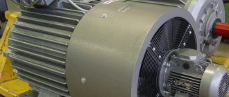
What is an asynchronous motor and its principle of operation
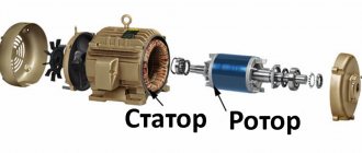
Any electric motor is a device for converting electrical energy into mechanical energy. An electric motor consists of a stationary part (stator) and a moving part (rotor). The structure of the stator is such that it looks like a hollow cylinder, inside of which there is a winding. A moving part, the rotor, is inserted into this cylindrical hole. It also has the appearance of a cylinder, but is smaller in size. There is an air gap between the stator and the rotor, allowing the rotor to rotate freely. The rotor rotates due to currents induced by the magnetic field of the stator. Based on the method of rotation, motors are divided into synchronous and asynchronous.
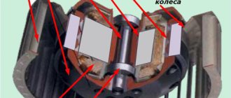
This is what a disassembled asynchronous motor with a squirrel-cage rotor looks like
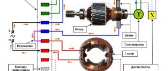
An asynchronous electric motor differs in that the rotation speed of the rotor and the magnetic field created by the stator are unequal. That is, the rotor rotates asynchronously with the field, which gives this type of machine its name. Typically, in operating mode its rotation speed is lower. The second name for this type of motor is induction. This name is due to the fact that the movement occurs due to induction currents induced on it.
Read also: Automatic argon arc welding with consumable electrode
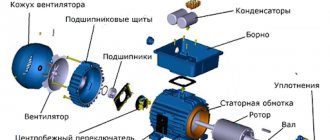
Asynchronous motor disassembled: main components and parts
The operating principle of an asynchronous motor can be briefly described as follows. When the motor is turned on, current is supplied to the stator windings, which creates an alternating magnetic field. The rotor enters the area of action of the power lines and begins to rotate following the alternating field of the stator.
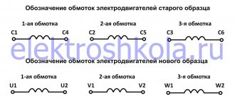
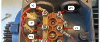
Stator winding of an asynchronous motor
In the grooves of the stator core there is a three-phase winding (in the case of single-phase motors - two-phase), which is connected to a three-phase (single-phase) alternating current network. Three-phase symmetrical stator winding of an asynchronous motor
consists of three single-phase windings that are connected to each other according to a star (U) or delta (D) circuit. Between themselves, the axes of the windings are shifted in space by an electrical angle of 360/m=360/3=120° (v is the number of phases).
Two conductors located in grooves spaced from each other at a distance y, called the winding pitch, form the simplest circuit - a turn. Each turn can consist of several parallel (elementary) conductors. The turns, laid in the same pair of slots and connected to each other in series, form a coil or winding section. A set of coils (sections) lying in adjacent slots connected in series to each other is called a coil group. Stator winding of an asynchronous motor
consists of a collection of coil groups that can be connected in series, parallel or series-parallel. Parallel-connected coil groups form parallel winding branches, the number of which is designated a1.
The distance between the axes of adjacent teeth (grooves) is called tooth division t (measured in units of length or degrees). The winding pitch y can be measured in tooth divisions and in degrees. The part of the stator circumference that falls on one pole of the magnetic field is called the pole division τ. Pole divisions can be measured in units of length, degrees, or tooth divisions. For the first two cases, the polar division is calculated by the formula
(5)
where D is the diameter of the stator bore, m; 2p is the number of poles of the motor’s magnetic field.
From formula (5) it follows that the geometric angle corresponding to the pole division is equal to 180° for a two-pole machine, 90° for a four-pole machine, 60° for a six-pole machine, etc. But by definition, the pole division is the part of the circle per one pole. And the pole always occupies an electrical angle of 180°, or half a period. From this follows the connection between electrical and geometric angles in electrical machines in the form
1° (geometric angle) = p° (electrical angle). (6)
In the special case when 2p = 2, these angles coincide.
The winding pitch y, equal to the pole division τ, is called diametrical (winding with diametrical pitch). If y<τ, the winding pitch is called shortened, if y>τ - extended. The difference τ—y is called shortening. The relative value of the shortening β is equal to:
β=y/τ. (7)
The sides of the coils located in adjacent grooves occupy q tooth divisions, called the number of grooves per pole and phase. Knowing the number of slots on the stator z1, the value of q1 for multiphase windings can be determined by the formula
q1=z1 (2pm), (8).
and for three-phase windings
q1=z1/6p.
According to the type of coils, the stator winding of an asynchronous motor
is divided into random windings with soft coils and windings with hard coils. Soft coils are made from round copper or aluminum wire. Such coils are wound onto templates, where they are pre-shaped, and then placed in insulated trapezoidal grooves (Fig. 9). After laying the coils and securing them in the grooves using wedges or covers, the frontal parts are formed and banded. Interphase insulating spacers are installed during winding installation. The stator wound in this way is impregnated. The entire process of manufacturing random windings can be completely mechanized.
Rice. 9. Grooves and stator windings: a - semi-closed groove, single-layer winding; b - semi-closed groove, double-layer winding; c - open groove. double-layer winding; g - half-open groove, single-layer winding; 1 - winding wire; 2 - groove box; 3 - gasket under the wedge; 4 - spacer between layers; 5 - groove wedge
Rigid coils (or half-coils) are made from rectangular insulated wire. The final shape is given to the coils before installation. In motors with voltages up to 0.66 kV, slot insulation is installed in the core before the coils are laid, and the coils themselves are not insulated. After placing the coils in half-open slots (Fig. 9), the wound stator is impregnated and dried.
In motors with voltages of 3 kV and above, coils with body insulation are used, which is applied to the coils before they are placed in open slots (Fig. 9). Currently, thermoplastic insulation and thermosetting insulation of the “Monolith” type are used.
Random stator windings of an asynchronous motor
have the following advantages over windings with rigid coils of rectangular wire:
- the possibility of complete mechanization of the entire manufacturing process;
- shorter length and reach of the frontal parts, and therefore lower losses, higher efficiency, shorter length of the active part of the machine;
- the trapezoidal shape of the groove is more favorable from the point of view of using the tooth zone;
- smaller opening of the groove, providing smaller flux pulsations in the air gap, i.e., smaller additional losses and magnetizing current;
- greater production manufacturability: winding of coil groups, in some cases also of phase windings, is carried out without breaking, i.e., fewer solderings; the possibility of laying the winding in the grooves of the core without a housing makes winding and impregnation easier and cheaper.
Due to these advantages, soft random stator windings of an asynchronous motor
cheaper and less labor intensive.
The advantages of rigid windings are a higher fill factor due to the use of rectangular wires and greater reliability associated with lower technological defects, since ready-made insulated and tested coils are placed in the grooves, which are subject to less deformation.
Due to these advantages, random stator windings of an asynchronous motor
are preferred for asynchronous motors with voltages up to 1 kV and power up to 100 kW. In motors with a power above 100 kW and in motors with a voltage of 3 kV and above, the windings are made of rectangular wire (from rigid coils).
Based on the placement of the coils in the slots, single-layer and double-layer windings are distinguished. The coil side of a single-layer winding occupies the groove completely; with a double-layer winding, two sides of different coils are placed together in the groove, one of which is installed at the bottom of the groove, and the other in the part of the groove adjacent to the stator bore.
The mechanization of winding installation at electrical machine-building plants has led to the widespread use of single-layer concentric windings in motors with power up to 10-15 kW. For motors of higher power (15-100 kW), more labor-intensive one-two-layer and two-layer random windings made of round wire are used. For motors with a power above 100 kW, the windings of which are laid manually, double-layer windings are used.
One- or two-layer concentric windings combine the advantages of single-layer windings in terms of mechanized laying and two-layer windings (possibly shortening the pitch and reducing the length of the frontal parts).
When repairing asynchronous motors in the absence of mechanized winding installation, two-layer windings are used.
Winding of DC and AC machines
At high currents, the cross-sections of the section conductors turn out to be so large that making the coils by winding on a template and, in particular, bending
Heads
represent large
difficulties. In these cases, the winding sections are made from individual bars called half-sections. The half-sections are connected to each other with clamps and soldered. This connection corresponds to the head in the coil winding.
Windings made in this way are called core windings.
Sometimes windings consisting of large cross-section rectangular conductors are called rod windings in cases where they are made in a whole section and have a head the same as in a coil winding.
The half-section rods of the wave and loop windings are shown in Fig. 4-10 and 4-11. They are made by bending on a special template. The half-sections are connected with clamps and sealed after the armatures are laid in the grooves.
Step windings are made in the form of rod windings from separate half-sections.