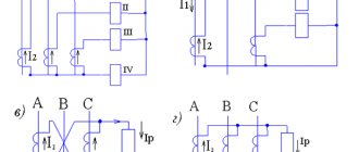
Electrical energy on an industrial scale cannot be transmitted in the form of single-phase alternating current. For this purpose, three-phase current is used, and three-phase transformers are used for its transmission. One of the ways to transform three-phase current is the use of three single-phase transformers.
The connection of the primary and secondary windings in these devices is carried out in one of the three-phase systems - star or delta. It is on this principle that powerful single-phase transformers operate, which are equipped in large power plants. Their primary windings are connected to the corresponding phases of the generators, and the secondary windings, connected in a star, are connected to the corresponding phases of the power lines.
Operating principle of a three-phase transformer
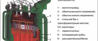
As can be seen from the diagram above, instead of three single-phase devices, one three-phase transformer can be used. Its magnetic circuit consists of three rods, which are closed by yokes at the top and bottom. A primary and secondary winding is wound on each rod, then connected by a star or triangle. Each rod with windings is essentially a single-phase transformer. At the same time, it performs the function of a separate phase of a three-phase transformer.
Under the influence of the primary winding current, a magnetic flux appears in all rods. It is necessary to take into account the belonging of each such winding to one of the phases included in the three-phase system. Therefore, the currents flowing through these windings, as well as the applied voltages, are three-phase. Therefore, the generated magnetic fluxes are also three-phase.
Previously, it was believed that the movement of the magnetic flux occurs along a closed path, that is, passing along the rod, it returns to its beginning. In three-phase transformers there is no such return path; it is simply not necessary, provided the phase loads are the same. In addition, there is no need for a neutral star connection.
Power transformers 10(6)/0.4 kV. Areas of application of different winding connection schemes
The lack of a clear understanding among manufacturers and customers about the fundamental differences in the properties of low-power power transformers with different winding connection schemes leads to errors in their use. Moreover, the incorrect choice of connection diagram for transformer windings not only worsens the technical performance of electrical installations and reduces the quality of electricity, but also leads to serious accidents.
Nizhny Novgorod designers Alevtina Ivanovna Fedorovskaya and Vladimir Semenovich Fishman remind us of this, who in their material focus on the difference in the response of transformers to asymmetrical currents containing a zero-sequence component.
Alevtina Fedorovskaya, technical director
Vladimir Fishman, chief specialist of the Group Branch "Energosetproekt - NN - SESH", Nizhny Novgorod
Winding connection diagrams and transformer properties
In accordance with GOST 11677-85 [1], power transformers 10(6)/0.4 kV with a power from 25 to 250 kVA can be manufactured with the following winding connection diagrams:
— “star/star” – Y/Yн;
— “triangle-star” – D/Yн;
— “star-zigzag” – Y/Zн.
The fundamental difference in the technical characteristics of transformers with different winding connection diagrams is the different response to asymmetrical currents containing a zero-sequence component. These are primarily single-phase through short circuits, as well as operating modes with uneven phase loading.
As is known, 6(10)/0.4 kV power transformers have a three-rod steel core, on each rod of which there are primary and secondary windings of the corresponding phase - A, B and C. The magnetic fluxes of the three phases in symmetrical operating modes circulate in the steel core of the transformer and do not go beyond it.
What happens when symmetry is broken with a predominance of the load of one of the phases on the 0.4 kV side? Such operating modes are studied using the theory of symmetrical components [2]. According to this theory, any asymmetrical mode of operation of a three-phase network is represented as a geometric sum of three symmetrical components of current and voltage: these are the direct, negative and zero sequence components.
Let's consider the mode of maximum single-phase asymmetry - the mode of single-phase short circuit (SSC) on the 0.4 kV side of a transformer with a D/Yn winding connection diagram.
The picture of the currents of symmetrical components in the windings in this mode is shown in Fig. 1. In undamaged phases on the 0.4 kV side, the geometric sum of the three symmetrical current components is zero (we neglect the operating load of the phases), and in the damaged phase this sum is maximum and equal to the short-circuit current. Its value is determined by the well-known formula:
(1)
where U l
– linear voltage;
R1
,
R0
,
X1
,
X0
– active and reactance of positive and zero sequence, respectively.
Positive sequence resistance
Positive sequence resistors R1
and
X1
of transformers with different winding connection diagrams are determined by the same formulas and differ slightly:
Looking at the catalogs, it is easy to see that the known values of Rkz
and
Uk
practically do not depend on the connection diagrams of the transformer windings, and therefore, the positive sequence resistance does not depend on them.
In contrast to these resistances, the zero-sequence resistances of transformers with different winding connection schemes are fundamentally different.
Zero sequence resistances
Let's consider the picture of current vectors and magnetic fluxes in a transformer with a D/Yn winding connection diagram (Fig. 2).
In such transformers, direct, reverse and zero sequence currents flow in both the primary and secondary windings. In this case, the zero-sequence currents in the primary winding are closed inside it and do not go into the network. The magnetizing forces (ampere-turns) created by the zero-sequence currents of the primary and secondary windings are directed in opposite directions and almost completely compensate each other, which causes a small value of the transformer reactance. In this case, the positive and zero sequence resistances are approximately equal: R1
= R0;
X1 = X0 .
In transformers with a Y/Zn winding connection circuit in a similar OKZ mode, zero-sequence currents flow only through the secondary winding of the transformer, but they do not create a zero-sequence magnetic flux, which is explained by the peculiarity of the Zn - “zigzag” circuit.
This feature is that on each transformer rod there is one secondary half-winding of two different phases (Fig. 3). In the OKZ mode, the magnetizing forces created by the zero-sequence currents in these half-windings are directed in the opposite direction and cancel each other out. In this case, there are no zero-sequence currents in the primary winding. In such transformers, zero-sequence resistances are less than positive-sequence resistances: R0 < R1; X0 < X1
.
Rice. 1. Currents of symmetrical components in the windings of a transformer in single-phase short circuit mode
IA21
,
IA22
,
IA20
,
IB21
,
IB22
,
IB20
,
IC21
,
IC22
,
IC20
– currents of phases A, B, C of direct, reverse and zero sequences of the secondary winding;
IA11
,
IA12
,
IA10
,
IB11
,
IB12
,
IB10
,
IC11
,
IC12
,
IC10
– currents of phases A, B, C of direct, reverse and zero sequences of the primary winding.
Rice. 2. Directions of currents and zero-sequence magnetic fluxes in a transformer with a D/Yn winding connection diagram
Rice. 3. Directions of currents and zero-sequence magnetic fluxes in a transformer with a Y/Zn winding connection diagram
As follows from formula (1), this provides a greater value of the short-circuit current for transformers with Y/Zn circuits compared to transformers with D/Yn circuits.
Now let's turn to transformers with a connection diagram for windings Y/Yn. As is known, in windings connected in a star without an output zero point, zero sequence currents cannot flow. Therefore, in the OKZ mode, the currents of this sequence flow only in the secondary winding of the transformer.
The in-phase zero-sequence magnetic fluxes created by the secondary winding currents extend beyond the magnetic core and are closed through the metal casing of the transformer (Fig. 4). This determines the significantly larger value of the zero-sequence resistance of such transformers: R0 >> R1; X0 >> X1
.
Rice. 4. Directions of currents and zero-sequence magnetic fluxes in a transformer with a Y/Yn winding connection diagram
It should be noted that, unlike the positive sequence resistances of transformers, which can be calculated, the zero sequence resistances of transformers with Y/Yn winding connection circuits cannot be calculated. They can only be determined experimentally. The value of these resistances largely depends on the design of the transformer casing, on the size of the gaps between the core and the casing, etc.
The circuit for measuring zero sequence resistance is given in GOST 3484.1-88 [3]. Unfortunately, this document states that manufacturers carry out such measurements at the request of customers. Probably, in recent years there have been no such requests from customers, and manufacturers do not carry out these measurements on their own, believing that they are not necessary. As a result, designers use old reference data when performing calculations. However, it is necessary to use outdated information extremely carefully, because the designs of modern transformers, in particular casings, as well as the materials from which they are made, have changed significantly.
In addition, the data available today on the zero-sequence resistance of transformers is extremely scarce and contradictory. Thus, according to measurements made by the Minsk Transformer Plant many years ago, the zero-sequence reactance of transformers with Y/Yn winding connection circuits exceeds the positive-sequence resistance by an average of 10 times. At the same time, GOST 3484.1-88 contains a phrase that these resistances can differ by two orders of magnitude. And today the contradictions do not end there [4].
Why is it necessary to know the real resistance values?
It is necessary to know the real values of the zero-sequence resistances, since they determine the magnitude of the short-circuit current. The higher these resistances, the lower the short-circuit current, and accordingly it is more difficult to protect the transformer.
In normal operating modes, large zero-sequence resistances with uneven loading of the transformer phases on the 0.4 kV side lead to a deterioration in the quality of electricity for the consumer.
So, if we take R1 = R0, X1 = X0
, which is typical for transformers with D/Yn winding connection circuits, we get:
(2)
Thus, under these conditions, the short-circuit current at the terminals of the 0.4 kV transformer will be equal to the three-phase short-circuit current.
However, if R0>>R1
and
X0>>X1
, which is typical for transformers with winding connection circuits Y/Yn, then the value of the short-circuit current turns out to be significantly less than the three-phase short-circuit current, that is,
Iokz << I3fkz
. What difficulties may arise with protection, especially if it is performed on the side of the HV winding with 6 (10) kV fuses, can be shown with a specific example.
In Fig. Figure 5 shows a connection diagram for a 100 kVA transformer, 6/0.4 kV auxiliary power supply (TSN) of a 110/35/6 kV substation. At a substation with alternating operating current, such transformers are installed on the outdoor switchgear and connected to the air input coming from the power transformer to the input cell of the ZRU-6(10) kV. The transformer protection, including the 0.4 kV cable to the 0.4 kV switchboard, is carried out with 6 kV fuses. Short-circuit currents at the end of the zone protected by fuses - when 0.4 kV is input to the switchboard - are given in table. 1. As can be seen from it, the minimum value of the short-circuit current through 6 kV fuses occurs with a single-phase fault on the 0.4 kV side.
Table 1. Short circuit currents at the end of the fuse-protected zone behind the transformer 100 kVA, 6/0.4 kV, D/Yn when input to the switchboard 0.4 kV
Rice. 5. Connection diagram for a 100 kVA, 6/0.4 kV transformer to power the auxiliary needs of a 110/35/6 kV substation
According to existing recommendations on the conditions for detuning from the inrush current of a magnetizing transformer with a power of 100 kVA, the rated current of the fuses is assumed to be equal to In.tr = (2 ÷ 3) In.tr
.
In this case, In.pr 2 · 10 A 20
.
We accept In.pr = 20
A.
The minimum disconnected current by a PKT-6 kV, 20 A fuse, according to the catalog data, is Imin.off.pr = 240 A
, which is significantly higher than the short-circuit currents given in table. 1.
Thus, protection with 6 kV PKT fuses turns out to be insensitive. Moreover, when the short-circuit current flows below the minimum switchable value, the fuse not only does not protect the equipment, but also destroys itself, causing an accident.
As a protective device, you can consider using fuses from foreign companies, for example the Merlin Gerin brand.
recommend choosing the rated current of the fuse from the condition Ipr.0.1s
12 Inom.tr. Using the time-current dependence given in [5], we determine that this condition is satisfied by the Fusarc fuse with a rated current of 20 A, the minimum shutdown current of which is 55 A. It would seem that this fuse reliably protects electrical equipment, since the minimum current it turns off is less minimum short-circuit current: 62 A 55 A. However, the shutdown time of this fuse for a short-circuit current equal to 62 A is 7 s. With such a long time, it is necessary to take into account the effect of current decay caused by an increase in the active resistance of the cable due to its heating [6]. As a result of the current decline, its value approaches the minimum fuse disconnecting current of –55 A, which makes the protection unreliable.
The reliability of protection can be improved by using a 6/0.4 kV power transformer with a Y/Zn winding connection diagram. In this case, the minimum short-circuit current through the fuses increases to 80 A, and the fuse-off time is reduced to 0.6 s and the protection becomes quite reliable.
If in the considered example a transformer with a Y/Yn winding connection circuit is used, then the minimum short-circuit current through the fuses will be only 22 A. Obviously, it is impossible to protect electrical equipment with 6 kV fuses at such a current. The disadvantages of transformers with a Y/Yn winding connection circuit also appear in normal operating modes with uneven phase loading. Voltage losses in a more loaded phase can increase sharply compared to less loaded phases, especially when the transformer load is high and the load cos j is low.
However, does all of the above mean that transformers with a Y/Yn winding connection diagram should not be manufactured at all? It appears that this is not the case. A large zero-sequence resistance of a transformer is not always a disadvantage. For example, when using transformers of more than 1000 kVA, the problem of stability of single-phase switching equipment of 0.4 kV to short-circuit current may arise. In this case, a large value of the zero-sequence resistance of the transformer with the Y/Yn circuit will help solve this problem.
As for the protection of such transformers, it is solved using relay protection and a 6 (10) kV switch, and on the low side - using an input circuit breaker.
conclusions
For low-power transformers (from 25 to 250 kVA), protected by fuses on the HV side, the Y/Zn winding connection scheme has an absolute advantage. The D/Yn scheme gives a slightly lesser effect. The Y/Yn circuit should not be used for such transformers.
The connection diagram for the windings of Y/Yn transformers can be used in relatively rare cases for more powerful transformers when it is necessary to limit the single-phase short-circuit current in order to increase the stability of switching equipment.
Manufacturers of power transformers should necessarily measure their zero-sequence resistance.
Literature
1.
GOST 11677-85. Power transformers. General technical conditions.
2.
Ulyanov S. A. Short circuits in electrical systems. – M.: Gosenergoizdat, 1952. – 280 p.
3
. GOST 3484.1-88 (ST SEV 1070-78). Power transformers. Electromagnetic testing methods.
4.
Handbook on the design of power supply, power lines and networks / Ed. Bolshama Ya.M., Krupovicha V.I., Samovera M.L. et al. - M.: Energia, 1975. - 696 p.
5.
Catalog for Fusarc Merlin Gerin fuses (DIN standard).
6.
GOST 28249-93. Short circuits in electrical installations. Calculation methods in AC electrical installations with voltage up to 1 kV.
How three-phase current is transmitted
The primary power source in most cases is the electrical network. Its voltage is presented as a sinusoid with a frequency of 50 Hz. However, in cases where power transmission lines are long, the transmitted energy is radiated into the surrounding space, which leads to additional losses. Therefore, three-phase voltage is used in high-power power supply circuits.
In order to reduce radiation, the sum of the voltages on all three phases must be zero at any time. For this purpose, the sinusoidal voltage is shifted in phase in each wire relative to each other by 120 degrees. In this state, the transmission of electricity can be carried out in two ways: using four or three wires of the transmission line. Conditional diagrams of each option are shown in the figure.
The four-wire line allows you to supply the consumer with two types of voltage: phase (220 V) and linear (380 V). The three-wire circuit allows you to output only linear voltages. The formation of linear voltage is described using a vector diagram of phase voltages. With a positive phase alternation, they conditionally increase clockwise. To connect the windings of three-phase transformers, two main methods are used - star and delta.
Star connection
It is recommended to consider this type of connection using the example of a star-star circuit. In this case, the current source and load are connected using the star method.
In the figure, the designation of phase voltages generated by the secondary windings of the transformer is indicated by the symbols UA, UB, and UC. From the phase windings to the load there are conductors that perform the function of linear wires. It is necessary to take into account the presence of voltage not only between the neutral and linear wires, but also between two linear conductors. This voltage is called linear and is designated UAC or UCA.
The line voltage value always exceeds the phase voltage. The difference between them is √3 times, since it represents the vector difference of the phase voltages. Thus, a three-phase power line allows you to receive not only 380 V, but also 220 V, depending on which circuit the load is connected to.
What is a connection group?
Figure 1 shows 10 transformers, the windings of which are connected in different ways, and this is not all of the possible connections. Without considering for now what the differences are, let's pay attention to the vector diagrams placed next to the diagrams, which are arranged in the following order: on the left - a vector diagram of the voltages of the primary winding, in the middle - a vector diagram of the voltages of the secondary winding, on the right - vector diagrams of the voltages of both windings are combined (in hours). Their “centers of gravity” are located in the center of the watch dial. The minute hand of the clock coincides with the direction of one of the voltage vectors of the primary winding (in Figure 1 with vector B). The hour hand coincides with the voltage vector of the secondary winding of the same phase, that is, with vector b.
Figure 1. Examples of the formation of groups of transformer connections. The beginnings of the primary windings are designated A, B, C, the ends X, Y, Z. The beginnings of the secondary windings are a, b, c, ends x, y, z.
Please note that the location of the vectors of the primary and secondary stars is compared. Therefore, in the case of connecting the winding into a triangle, it is necessary, before determining the connection group, to enter a star into the triangle. After this, looking at the stars, the arrows are directed along the star vectors to vertices B and b (A and a, C and c).
From Figure 1 it is easy to see that several circuits, despite the difference in connections, give the same shift in the vectors of the same voltages, which is clearly visible from the corresponding “clocks”, since they indicate the same time.
Several circuits that give the same shift form a connection group. In other words, the secondary voltages of the same phases of all transformers that have the same connection group are in phase. Therefore, they can be connected in parallel without risking equalizing current.
There can be twelve main groups (1 hour, 2 hours, ..., 12 hours) - according to the number of digits on the dial. This is explained by the fact that the vectors of primary and secondary voltages, depending on the connection diagram of the windings and their location on the rods, can have shifts that are multiples of 30°. Thus, the 1 hour group corresponds to a shift of 30°, the 2 hour group - 60°, 3 hours - 90°, 4 hours - 120°, and so on. A shift of 360° (or, what is the same, no shift, since 360° and 0° are the same thing) has a group of 12 or 0 hours. With a shift of 6 hours, the voltage vectors of the same phases of the primary and secondary windings are directed in exactly the opposite direction .
Even groups (2, 4, 6, 8, 10, 12) are obtained if both the high voltage (HV) and low voltage (LV) windings have the same connections - both in star or both in delta. Connecting one winding in a zigzag - star with the other winding connected in a triangle gives even groups.
Odd groups (1, 3, 5, 7, 9, 11) are obtained if one winding is connected in a star, the other in a triangle, and also if one winding is connected in a zigzag - star, and the other - in a star.

