Electrician in the house
Encyclopedia about electricity from A to Z
Masters catalog
Find the best master or company in your city
Cable type VVG and its standard sizes
VVG brand cables are widely used both in private construction and in industry. This is due to the fact that it has a fairly wide range of standard sizes, is easy to install, and its cost is relatively low compared to other similar products.
Moreover, the characteristics of this cable allow it to be used in almost all low-voltage networks up to 1 kV, where there is no exposure to particularly aggressive environments. Based on this, we decided to consider this type of wire in more detail.
- Explanation of the VVG cable abbreviation
- VVG cable structure
- Characteristics of VVG cable Mechanical characteristics of VVG cable
- Electrical characteristics of VVG cable
Scope of application of the VVGng(A)-LS cable
The VVGng(A)-LS cable is designed for operation in electrical networks under voltage of 0.66 or 1 kV with a frequency of up to 50 Hz. It is equally suitable for use in cold, temperate and tropical climates. It is allowed to lay the VVGng(A)-LS cable under the following conditions:
- in dry and damp rooms, including partially flooded ones, with any level of corrosive activity;
- for special cable structures, blocks and bridges;
- in the air in the absence of risk of mechanical damage;
- in rooms with high fire safety requirements;
- in explosive zones of categories B-Ib, B-Ig, B-II and B-IIa;
- at nuclear power facilities.
The absence of armor allows the VVGng(A)-LS cable to be laid in areas prone to vibration. It is allowed to install it on horizontal, vertical and inclined cable routes.
Types and types of VVG cable
Absolutely any cable installed indoors is marked with a certain marking. Using it you can see the necessary characteristics of the purchased product. But for those people who are far from electrical engineering work, it is difficult to decipher the various abbreviations. They do not understand what VVGng means, and how the marking differs from a regular VVG cable. This issue needs to be dealt with.
Types of VVG cables:
- VVG wire has PVC insulation. With this component, the wire becomes fire retardant and self-extinguishing in the event of an open fire.
- If “ng” is added to the letters VVG on the marking, this means that the insulating word also contains halogen particles. With the help of this element, the combustion process can be neutralized - the wire simply does not burn.
- Explanation of the VVGng-LS marking - the shell is coated with a special compound that does not emit smoke when burning. It is known that it is wiring exposed to fire that causes large amounts of smoke to spread throughout the facility during fires. Because of this, people lose orientation in space and die in fires. That is why manufacturers began to use halogen-free polyvinyl chloride. In this way, gas emission was reduced.
- VVGngfr-LS. This model is very similar to the previous one, but additionally has significant fire resistance. If the “LS” cable is exposed to open fire, then, as in the previous version, the gas emission will be minimal. If you use group wiring, the combustion simply will not spread throughout the room.
- The VVGng-fr-ls cable is made of halogen-free materials. This is precisely the main difference between the wire and other brands. By using plastics consisting of halogen-free materials, manufacturers create high-quality insulation. When an open flame hits the cable, very little smoke will be emitted, unlike other cable options not included in the KVVG line. The wire is purchased for placement in objects that may be subject to fire.
If the cable is marked “LS”, then you can be sure that in the event of a fire, the burnt wire produces a minimal amount of smoke. And this is very important for the rescue and evacuation of people. LS means the English phrase Low smoke, that is, “light smoke”.
Designation of the number of cores, their cross-section and cable structure
Further designations indicate the number of cores, their thickness and design features:
- The first number is the number of cores.
- The second is their cross-sectional area.
For example, a VVG 3×2 wire has 3 cores with a nominal cross-section of 2 mm2.
The choice of core cross-section is made taking into account the expected load that will be connected via cable:
- A VVG 3×1.5 cable is suitable for lighting.
- The sockets can bear a much more significant load, so the wire needs to be more solid. The cross-sectional area of its cores should not be less than 2.5 mm2, so the “minimum” socket outlet is VVG 3×2.5 cable. But it’s better to take it with a reserve so that you don’t have to redo the wiring later.
- To connect electric ovens, washing machines or other energy-consuming electrical appliances, the wire cross-section must be at least 4 mm2.
The marking also shows the cable structure:
- If the core consists of several twisted wires, then the letter “M” is indicated; single-wire wires are indicated by the letter “O”.
- Core shape: “C” – sector, “K” – round.
- The “+” sign indicates the characteristics of the neutral or ground wire, if they exist and differ in cross-section from the rest of the wires.
- The last digit shows the rated voltage in kV for which the cable is designed.
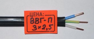
- A wire with the designation VVG-p (“p” - flat) is used quite rarely in everyday life. The veins in it are laid in a row, it itself has a flat shape. Mainly used for connecting powerful industrial installations.
VVGng cable: technical characteristics
- operating frequency – 50 Hz;
- laying of communications is carried out at temperatures above -15 ° C, without preheating;
- cables are operated in temperature conditions: from minus 30 °C to + 50 °C;
- when installing single- and multi-core VVGNG ls cable, a minimum bending radius of 7.5-10 outer diameters is allowed;
- prolonged heating of the cores up to a temperature of +70 °C is allowed;
- operating current with voltage up to 0.66 kV, wire with additional characteristics operates at higher voltages;
- cable combustion begins at a temperature of +400 °C;
- Manufacturers guarantee safe operation of the cable for 30 years, subject to compliance with technological discipline; it is recommended to check the cables in use every 5 years for insulation damage;
- operation of communications in conditions of high humidity and at high altitudes is allowed.
Design features
A description of the design of an electrical cable brand VVG NG ls is given by GOST 22483. It includes a single-, double- or multi-wire conductor made of copper. A polyvinyl chloride composition characterized by a low fire hazard coefficient is used as an insulating material.
VVGNG technical power cables are produced both round and flat. There can be a maximum of 5 current-carrying cores in a wire. They come in round and sector shapes. The cores are insulated with polyvinyl chloride in a distinctive color. So, for example, the core responsible for zero has a blue coating, and the grounding is covered with a PVC composition of a greenish-yellow color.
The conductors are class 1-2, twisted, the wire is filled with extruded PVC plastic, which has low smoke and gas emissions. In two- and three-core models, cores of the same cross-section are used; in four- and five-core wires, one core has a smaller size.
The thickness of the plastic compound must be at least 0.3 mm; the sector cores do not need to be filled with an inner sheath of plastic compound; it is enough to overlap them with polyethylene terephthalate film or thermally bonded fabric. The outer covering is made of PVC composition.
Conductor
Round, segment or sector shape - these are the main design forms of current conductors in a cable. The range of core sections is standard; the conductors themselves are made of aluminum or copper.
Interesting. Electrolytic copper is used, grades MO or MI. Aluminum is taken grades AO or A01.
Phase insulation
Each phase conductor in the cable is covered with individual (phase) insulation. Also P.L. Schilling in the mid-19th century used gutta-percha insulation for wires used to detonate mines at sea.
Modern phase insulation must meet the following requirements:
- flexibility;
- mechanical strength;
- electrical strength.
The choice between flexibility and thinning is always problematic. Electric strength is the main indicator for insulation. It can be made of cross-linked polyethylene, polyvinyl chloride, rubber or oil-impregnated paper.
Important! Reducing the thickness increases flexibility, reduces weight, and improves heat dissipation, which means the cable can withstand high operating current. Reducing the insulation thickness leads to the likelihood of breakdown, therefore, the electrical strength decreases.
Outer shell
This is a protective layer covering the entire complex structure of the SC. The outer shell can be made of PVC (polyvinyl chloride plastic). For example, VVGP ng, if you pay attention to its marking, has a PVC shell.
Additional items
These include components that increase the internal insulation, strength and protection of the cores. Additional elements may be as follows:
- shielding braid;
- waist insulation;
- lining (pillow) under the armor;
- protective outer layer of metal strips (armor);
- internal filler of spaces between conductors.
Number and cross-section of cores
The SC can include from 1 to 5 current-carrying wires. The nominal cross-section of conductors ranges from 1.5 to 1000 mm2. In SCs they have the same cross-section, but in four-core cables one of the conductors may have a smaller cross-section. Usually this is a neutral conductor.
Deciphering the markings
Deciphering the characteristics of a wire or cable begins with the symbolic marking applied by the manufacturer to the insulation - it usually contains comprehensive information about the materials from which the conductor is made and other parameters. The order of symbols and their meanings are established by GOST, with the exception of situations when conductors are made
So, the first letter in the marking of any cable indicates the metal of the cores, but it is not always placed. The fact is that only aluminum wires are marked with a capital letter “A”. And if there are copper conductors, no marking is applied.
The second (in copper wires - the first) letter in the marking allows you to find out the purpose of the cable. The following codes are used here:
- P – flat;
- M – installation;
- Ш or П(У) – installation;
- MG – installation cable with flexible cores;
- K – control.
The third letter in the marking of electrical conductors serves to designate the insulating material of the conductors. Their variety is quite large:
- V/VR – polyvinyl chloride shell;
- R – rubber is used to insulate the cores;
- N/NR – fire-resistant rubber or nayrite;
- K – nylon shell;
- L – varnished insulation;
- P – polyethylene;
- F – fold;
- E – enamel;
- Ш – polyamide type silk;
- O – polyamide silk insulation is braided;
- E – shielded insulation;
- G – insulating shell with flexible conductors;
- C – fiberglass;
- T – the insulation design includes a support cable.
The marking of a rubber insulated cable, which has additional protection made of nayrite or PVC, is done as follows: first indicate the above symbols, and then the marking of the cores.
The decoding of the following symbol makes it clear what design features this cable has. According to the current GOST, these are the following letters:
- A – asphalted cable;
- B – cable with armor tapes;
- G – flexible wire without protection;
- K – cable armored with round wire;
- T – wire intended for laying in pipes;
- A – the cable has additional braided protection.
The abbreviation frls at the end of the cable marking refers to the degree of compliance with fire safety requirements. FRLS is formed from two abbreviations describing the characteristics of conductor materials: FR - fire resistance, LS - low smoke emission
Thanks to this, the frls cable does not support combustion even when laid in a group, and even remains operational for some time in fire conditions (this is important, for example, for the operation of a fire protection system). Most often, the frls version uses cables VVGng-FRLS (power), KPSEng(A)-FRLS, KSBNG(A)-FRLS (cables for fire protection systems)
Decoding the abbreviation
- the letter A at the beginning of the abbreviation means that the core material is aluminum; if the letter A is absent in the name of the cable, then the core is made of copper;
- the first letter B indicates the material used for internal insulation; this letter codes polyvinyl chloride;
- the second B denotes the material from which the outer shell is made, it indicates polyvinyl chloride;
- the letter G indicates the absence of a protective coating (G - bare);
- the letters ng indicate that the wire is flame retardant;
- the English letters ls (low smoke) indicate that the wire has low smoke emission;
- the letter P means that the cable has an inner sheath made of thermoplastic polyethylene;
- the letters BB indicate the presence of an armored coating made of steel tape;
- the letters Шв give information about the outer layer of the polyvinyl chloride hose.
Principles of marking cable products
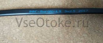
Cable markings have been created to identify each element of the conductive product, the cable's technical characteristics and its intended use. On the insulating coating, these data are written in exactly the stated order, with each symbol corresponding to a specific material or condition of use:
- The first symbol represents the material designation of the conductive element. If there is no symbol, the wires are copper; if there are aluminum wires, the first letter is “A”;
- The second symbol is responsible for the degree of cable flexibility. The presence of the letter G on the insulating coating indicates flexibility when the number of cores is more than one. The absence of symbols indicates a single-core cable design.
- The third letter corresponds to the insulating material. Possible options: B - polyvinyl chloride coating, P - polyethylene, P - rubber, NR - non-flammable rubber (most often with the addition of chalk), marking the wires with the letter F indicates the use of fluoroplastic, the symbol C indicates the use of film insulating material;
- The fourth character of the cable brand indicates the material of the outer covering and reinforcement against external damage. Possible symbols: BBG - metal profiled tape, Bn - reinforcement with steel tapes, protected from fire, B - polyvinyl chloride insulating material, D - braided with double wire, K - braided with metal wires that enclose the conductive element in a solid cover;
- The last, 5th character, is required to mark the type of protective coating and designate the design of the conductive core.
Cable examples
Decoding of other types of VVGng cable
- VVG – interpretation: standard copper wire, does not spread flame when laid alone, has polyvinyl chloride insulation of the inner and outer layers;
- VVGNG hf – there are no halogens, the wire is used in group laying, taking into account the volume of flammable load for rooms filled with working computer and microprocessor equipment, as well as in rooms visited by a large number of people;
- VVG PNG - interpretation: core insulation is made of thermoplastic polyethylene, flat design, used for making wiring in industrial buildings, non-flammable;
- vvgng p – conductors are laid in one plane, used for laying in air on cable racks or blocks, without mechanical stretching;
- kvvgng ls - control cable, fixedly attached to electrical appliances, devices and clamp assemblies, can be laid externally, in cable ducts and indoors, works in aggressive conditions, ensures fire safety of cable communications in group installations;
- VVGNG-frls - VVGNG frls cable is an analogue of the VVGNG-LS sample, with increased fire resistance, this is confirmed by the decoding of the letters frls (Fire Resistance Low Smoke), characterized by reduced formation of smoke and gas, prevents combustion in group gaskets;
- nym cable – power wire, application: stationary installation inside industrial and domestic buildings of power and lighting lines. nym wires stand for “standard cable in the German classification with polyvinyl chloride insulation with an outer sheath.”
Weight and dimensions parameters of VVGNG cables include:
- number of cores;
- core cross-section in mm²;
- outside diameter;
- wire weight, kg/km. Gngi
An example of the weight and size parameters of a 3×1 5, 3×1 wire: number of cores 3 pieces, core cross-section 1.5 mm².
The weight of the VVGNG cable for current with an operating voltage of 660 V and 1000 V differs by several kilograms.
For example: 1 km of wire VVGNG 3×1 5 for a current voltage of 660 V weighs 96 kg, and for 1000 V - 122 kg.
NYM cable
Copper solid-wire conductors with current, with PVC insulation and a protective sheath, do not burn, are not afraid of aggressive environments. The first 5 cores are available with a cut: 1.5 - 35 square units. - in the body of a white protective sphere. The conductors are adjacent to dense coated rubber: there are no halogens, the cord is durable and heat-resistant. Its functionality is from -40°C to +70°C and is moisture resistant. Colored insulation: light green, bluish, brown.
The NYM cable serves lighting systems in technical and civil construction - voltage limit is 660 units. The product is laid indoors and outdoors, hiding it from the sun in a corrugation. Installation allows bending radius - at least 4 diameters. It goes in bays starting from 50 meters. When compared with VVG, this liner has only copper and solid wire cores. It is convenient to lay it.
Fire safety designation
In addition to other designations, special attention must be paid to fire safety markings, which is very important. Main parameters:
- The ng-frhf conductor can be used for group conduction - in the event of a fire, the fire will not spread. This is due to the fact that gaseous substances will not be formed during the combustion process.
- The designation ngfr-ls indicates a low spread of smoke and gaseous substances. This product can also be used in group settings.
- The ng-hf marking indicates that in the case of group wiring, no actively corrosive gaseous substances are formed in the event of a fire. In addition, such a conductor does not burn.
- The letters ng-LS indicate low levels of smoke and gas emissions. If the cable comes into contact with an open flame, combustion will not spread.
- Cable VVG-Png A - decoding indicates that the conductor is flat and is not subject to combustion even in an open fire.
You might be interested in this Characteristics of flexible metal hose for cable
If you are guided by this information, you can easily determine how popular conductors are deciphered. Some of them:
- VVG-Png is a flat, non-flammable cable, without armor, the outer and inner sheaths of which are made of polyvinyl chloride.
- VVGng A LS is a conductor, the inner and outer layers of which are made of PVC, non-flammable, low levels of smoke are emitted, the conductors are made of copper.
- For the VVG-Png A LS wire, the decoding is completely identical to the previous one, the only difference is that this type of cable is flat.
What to look for when purchasing
With a large selection of products, it will not be difficult to more accurately select the wiring of the required diameter to ensure the operation of electrical appliances of a certain power, which will save money when designing and installing wiring.
When purchasing a product, you should carefully check the quality of the product's insulation. The cable must have a smooth cut with insulation that securely wraps around the cores. The shell material should not have any smudges or signs of drying out, that is, it should be elastic without cracks.
You might be interested in SIP: decoding and characteristics of cable with and without insulation
To obtain complete information about the product, you should read the certificate of conformity and then rely on the technical data. Based on the operating conditions, along with the wires, you should also purchase the necessary accessories that provide additional protection when laying the cable.
Technical parameters of the VVG-Png(A)-LSLTx cable:
Fire hazard class according to GOST 31565-2012: P1b.8.2.1.2 Type of climatic modification UHL, placement categories 3 and 4 according to GOST 15150. Operating temperature range from -50 °C to 50 °C. Relative air humidity at temperatures up to 35 °C up to 98%. Laying without preheating is carried out at an air temperature not lower than -15 ° C. The permissible bending radius of cables during installation is at least 7.5 times the maximum outer diameter. The equivalent toxicity indicator of combustion products is more than 120 g/m3. Cables do not propagate combustion when laid in groups according to category A. Smoke formation during combustion and smoldering of cables does not lead to a decrease in light transmission in the test chamber by more than 50%. Fire resistance – at least 180 min. Mass fraction of hydrogen chloride released during combustion of polymer materials: – insulation – no more than 100 mg/g; – shells – no more than 80 mg/g. The long-term permissible heating temperature of cable cores during operation is no more than 70 °C. The long-term permissible heating temperature of cable cores in overload mode is no more than 90 °C. The maximum permissible heating temperature of cable cores during a short circuit (the second value for cables with conductive cores with a cross-section of more than 300 mm²) is no more than 160/140 °C. The duration of the short circuit should not exceed 5 s. The maximum heating temperature of the cores under the conditions of non-ignition during a short circuit is no more than 350 °C. The construction length of the cables is specified when ordering. Service life is 30 years from the date of manufacture of the cables.
The warranty period is 5 years from the date of commissioning of the cables, but no later than 6 months from the date of manufacture.
Shelf life: – in open areas – no more than 2 years; – under a canopy – no more than 5 years; – indoors – no more than 10 years.
Regulatory document: TU 16-705.496-2011, TU 16.K73.108-2013
Section, mm2: 1,5;10;16;2,5;4;6
Size and weight of cable VVGng(A)-LS, VVGng-LS for voltage 1 kV:
Number and cross-section of cores, pcs x sq. mm Cable weight, kg/km Outer diameter, mm1 kV1 kV
| 1×1.5 coolant | 48 | 5,4 |
| 1×2.5 coolant | 60 | 5,8 |
| 1×4.0 coolant | 85 | 6,6 |
| 1×6.0 coolant | 108 | 7,1 |
| 1×10 coolant | 152 | 7,9 |
| 1×16 coolant | 228 | 9,4 |
| 1×25 coolant | 333 | 11 |
| 1×35 coolant | 431 | 12 |
| 1×50 coolant | 565 | 13,4 |
| 1×70 | 832 | 15,9 |
| 1×95 | 1093 | 17,8 |
| 1×120 | 1365 | 19,8 |
| 1×150 | 1670 | 21,4 |
| 1×185 | 2082 | 24,8 |
| 1×240 | 2673 | 27,8 |
| 2×1.5 coolant | 129 | 9 |
| 2×2.5 coolant | 160 | 9,7 |
| 2×4.0 coolant | 230 | 11,4 |
| 2×6.0 coolant | 290 | 12,4 |
| 2×10 coolant | 402 | 14 |
| 2×16 coolant | 558 | 15,9 |
| 2×25 cool | 957 | 21,4 |
| 2×35 cool | 1236 | 23,7 |
| 2×50 cool | 1605 | 26,7 |
| 2×70 | 1702 | 25 |
| 2×95 | 2231 | 27,7 |
| 2×120 | 2734 | 29,8 |
| 2×150 | 3353 | 32,3 |
| 2×185 | 4109 | 35,5 |
| 2×240 | 5256 | 39,7 |
| 3x1.5 coolant | 149 | 9,4 |
| 3x2.5 coolant | 189 | 10,2 |
| 3x4 cooler | 276 | 12,1 |
| 3x6 cooler | 354 | 13,1 |
| 3x10 cooler | 500 | 14,9 |
| 3x16 cooler | 708 | 16,8 |
| 3x25 cooler | 1196 | 22,6 |
| 3x35 cooler | 1559 | 25,1 |
| 3x50 cool | 2038 | 28,2 |
| 3x70 | 2334 | 28 |
| 3x95 | 3123 | 31,6 |
| 3x120 | 3886 | 34,6 |
| 3x150 | 4721 | 37,7 |
| 3x185 | 5818 | 41,3 |
| 3x240 | 7610 | 46,9 |
| 3x2.5+1x1.5 coolant | 221 | 11,1 |
| 3x4+1x2.5 coolant | 324 | 13,2 |
| 3x6+1x4 coolant | 419 | 14,4 |
| 3x10+1x6 coolant | 591 | 16,3 |
| 3x16+1x10 coolant | 864 | 18,9 |
| 3x25+1x16 coolant | 1442 | 25 |
| 3x35+1x16 coolant | 1738 | 26,5 |
| 3x50+1x25 cool | 2307 | 29,9 |
| 3x70+1x35 | 2732 | 30,8 |
| 3x95+1x50 | 3701 | 35,3 |
| 3x120+1x70 | 4688 | 39 |
| 3x150+1x70 | 5521 | 42,1 |
| 3x185+1x95 | 6934 | 46,9 |
| 3x240+1x120 | 8943 | 52,8 |
| 4x1.5 coolant | 177 | 10,2 |
| 4x2.5 coolant | 227 | 11,1 |
| 4x4 coolant | 334 | 13,2 |
| 4x6 coolant | 433 | 14,4 |
| 4x10 cooler | 619 | 16,3 |
| 4x16 coolant | 905 | 18,9 |
| 4x25 coolant | 1507 | 25 |
| 4x35 cooler | 1939 | 27,4 |
| 4x50 cool | 2545 | 31 |
| 4x70 | 3042 | 30,7 |
| 4x95 | 4131 | 35 |
| 4x120 | 5085 | 37,7 |
| 4x150 | 6183 | 41,1 |
| 4x185 | 7678 | 45,3 |
| 4x240 | 9979 | 50,9 |
| 5x1.5 coolant | 212 | 11 |
| 5x2.5 coolant | 274 | 12 |
| 5x4 cooler | 405 | 14,4 |
| 5x6 cooler | 529 | 15,7 |
| 5x10 cooler | 782 | 18,3 |
| 5x16 cooler | 1138 | 20,8 |
| 5x25 cool | 1843 | 27,3 |
| 5x35 cooler | 2400 | 30,0 |
| 5x50 cool | 3196 | 34,4 |
| 5x70 | 4017 | 35,6 |
| 5x95 | 5246 | 40,0 |
| 5x120 | 6544 | 42,9 |
| 5x150 | 8132 | 47,8 |
| 5x185 | 9782 | 52,0 |
| 5x240 | 12783 | 58,4 |
Laying methods
The VVG cable can be used in the construction of various objects, as well as in underground trenches.
The laying method directly depends on the specific purpose. The conductor can be laid on various surfaces consisting of non-combustible materials. These include concrete, plaster, brick or plaster. The VVG cable can be laid openly under a variety of suspended structures. A prerequisite is the exclusion of any mechanical influences. If there is a possibility of damage to the conductor, you need to think about additional protection. Often, special channels, tubes, metal or corrugated hoses are used for this.
Protective elements are also installed when the wire is laid on objects consisting of flammable materials.
The most popular is the hidden method. It is often used in residential premises when the cable is laid under plaster. First you need to make grooves in the walls , and then treat the product with cement plaster. In such situations, the possibility of mechanical impacts is eliminated, so there is no need to use additional protection. The only exception is when the wire is laid in wooden buildings. This option can be used in structures made of fireproof materials, for example, in pipes.
There is no wire that can be laid underground without the use of special protective elements. This is due to the fact that the cable needs to be preserved for a long period, but it itself is not equipped with built-in protection. Because of this, certain elements of protection against mechanical damage are used. In most cases they are sealed boxes.
Open position
If you study the technical parameters of the cable, you can conclude that installation is allowed in surfaces made of difficult-to-flammable or non-flammable materials, for example brick, concrete, gypsum or plaster. In an open way, VVG wire can be laid under various suspended structures , such as cables and the like.
In this case, the gasket must be very reliable. Any mechanical influences should be excluded. If the cable may be damaged, additional protection must be provided. Usually, special channels, metal hoses, corrugated hoses or tubes are used for this purpose. Protection is installed if the open installation method is carried out on flammable objects, built, for example, from wood.
Hidden option
This installation method is the most popular and is used in residential premises. The wire is usually laid under the plaster. Until this point, grooves are made in the walls, and after that the cable is covered with plaster and cement. In this case, mechanical damage is excluded, and therefore there is no need to apply additional protection. The exception is when the cable is laid in wooden houses. Hidden gasket can be used in various fireproof materials, for example, in pipes.
Location underground
No type of cable can be laid underground without the use of special protection. This is because the wire needs to be preserved for a long time, but it itself is not equipped with built-in protection. That is why protective measures are taken against various mechanical damages. For underground installation, sealed boxes are used.
Connecting VVG cables to each other
Before moving on to the procedure for connecting the VVG cable, you should remember that this is a rather dangerous and responsible undertaking. Therefore, such a procedure should be carried out by electricians or other specialists in the field of electrical wiring.
Execution must be carried out in accordance with the following requirements:
- The value of the transition resistance of the parts of the connections should not exceed the resistance level of the section of the conductor.
- The docking area must be protected from moisture as much as possible.
- Protect the contact area from mechanical impacts.
- Select the correct coupling connection. They not only guarantee reliable fastening, but also provide tightness and protection. The couplings can be rubberized or plastic.
Installation work includes the following activities:
- To begin, put on rubber gloves and cut the ends of the VVG cable.
- The next step is to connect the cables or band them if the room is damp. The ringing is done using a special funnel or a porcelain sleeve. Banding has its own mandatory requirements. For example, sealing the insulating coating, as well as the timely release of current-conducting force to the outside.
- The next step is the assembly of the pre-selected coupling connection.
- After the structure has received its shape, it is necessary to ground the shell and armor.
- Then the protective layer must be filled with a special epoxy mass or compound.
At this stage, the wire should be left until the top layer dries. This will take from several hours to several days.
Wire testing
To put a flame retardant mark on a wire, it is necessary to test the wire in various ways.
To carry out the test, the conditions of a real fire are recreated in laboratory conditions. After this, the laboratory technician uses special equipment to measure the transparency of the air inside the room with the fire. These measurements must be taken both under normal conditions and after a fire. Smoke will reduce the light transmission of the room, and this will be recorded by the device. As a result, a trained worker will calculate the ratio of light transmittance before the experiment, as well as after the fire. For the wire to successfully pass the test, the change in transparency inside the room should be no more than 40%. Only in this case will it be possible to put the appropriate designation on the cable.
VVG cable laying temperature
The VVG power cable is quite resistant and can be used at temperatures from –50 to +50 degrees Celsius, and at a relative humidity of up to 99%.
It also allows maximum heating up to +70 degrees Celsius, which is a very good indicator. However, cable laying and installation must be carried out in the most pleasant temperature conditions, which, unfortunately, beginners often forget about.
So, in the case of independent installation and laying of the VVG cable, taking into account the absence of pre-heating of the room, it is necessary to take into account that the temperature should not be lower than –15 degrees Celsius.
In this case, the maximum temperature is no higher than +30 degrees.
Also consider humidity levels. If it is high, then in such a situation the minus indicator should be at the level of –5 degrees, and the positive indicator should not be higher than +25 degrees Celsius.
Continuous permissible current of VVG cable
Before purchasing a cable, it is necessary to take into account such an important characteristic as the long-term permissible current. In fact, the long-term permissible current that a VVG cable can support will vary depending on the number of cores, their cross-section method, as well as the conditions where exactly the electrical wire runs. In fact, the performance varies greatly depending on whether the wire is located on the ground or in the air.
As for the minimum permissible current, it is 19 amperes. However, it is better not to guess and study the detailed information so that you have an idea about the specification of the particular wire that you intend to purchase.
We present the characteristics depending on the nominal cross-section, number of cores, and permissible current.
| Nominal cross section | With two main cores | With three main cores | With four main cores |
| 1.5 | 24 | 21 | 19 |
| 2.5 | 33 | 28 | 26 |
| 4 | 44 | 37 | 34 |
| 10 | 76 | 66 | 61 |
| 25 | 134 | 115 | 107 |
| 35 | 166 | 141 | 131 |
| 50 | 208 | 177 | 165 |
Taking into account the data from the table above, we can assume that the rated current can be equal to from 0.66 to 1 kW, and its frequency will be equal to 50 Hz.
If we mean the minimum cross-sectional area of the cable, then the power will reach 31/2 kW.
If we consider such a concept as resistance, then it will also vary depending on the selected cross-sectional area of the conductors of a particular wire. If it is equal to the minimum value of one and a half square millimeters, then the resistance will be equal to 12 MOhm/km.
If the wire has a cross-section of 5 sq. mm, then the resistance will be 9 MOhm/km.
Moreover, this is an average indicator, which was detected at an average temperature of +20 degrees Celsius.
The VVG cable is most often placed in the wall under a layer of plaster. Therefore, everyone would like to purchase such a wire once and for all, so that for the next 30 years they can forget about its existence and not remember the problems. Unfortunately, the lack of ability to select a wire in accordance with its characteristics, as well as ignorance of the nuances of choice, can lead to problems with wiring. Or the wires will need to be replaced after a couple of years. Therefore, it is necessary to familiarize yourself with the information in detail and, from the entire variety of VVG cables, choose exactly the one that suits your characteristics.
And also do not forget about the need to check for certification and compliance with GOST before purchasing. By observing all these nuances, you will ensure yourself a thoughtful purchase that will not cause you any trouble.
You cannot do without a VVG cable if you want high-quality and safe wiring or connection. Provide yourself and your loved ones with healthy sleep and confidence in safety.
Main characteristics
One of the main characteristics indicates the nominal and minimum thickness of the insulating coating; it depends on the voltage and cross-section of the wires.
| Threshold voltage value (V) | Ø wires (mm2) | Nominal layer of insulation coating (mm) | Minimum permissible layer of insulating coating (mm) |
| 660 | From 1.00 to 2.50 | 0,62 | 0,46 |
| From 4.00 to 6.00 | 0,71 | 0,54 | |
| From 10.00 to 16.00 | 0,93 | 0,72 | |
| From 25.00 to 35.00 | 1,12 | 0,90 | |
| 50,00 | 1,32 | 1,08 | |
| 1000,0-2500,0 | 0,80 | 0,64 | 0,54 |
| From 4.00 to 16.00 | 1,10 | 0,82 | |
| From 25.00 to 35.00 | 1,22 | 1,02 | |
| 50,00 | 1,44 | 1,18 |
The next most important parameter is the characteristics of the insulating layer of the sheath; they depend on the total cross-section of all the wires of the electrical cable.
| Overall Ø (mm2) | Nominal layer of insulating sheath (mm) | Minimum insulation layer (mm) |
| Until 6.00 | 1,22 | 0,94 |
| From 6.00 to 15.00 | 1,54 | 1,20 |
| From 15.00 to 20.00 | 1,72 | 1,36 |
| From 20.00 to 30.00 | 1,92 | 1,54 |
| From 30.00 to 40.00 | 2,14 | 1,70 |
The threshold electric current strength, this indicator may depend on how many wires are in the cable and what their cross-section is. In addition, the location of the electrical cable (overhead line or underground wiring) influences. We recommend that you check this specification when purchasing cable products. Below is a table showing the threshold electric current for overhead lines.
| Ø(mm2) | Permissible electric current threshold (A) | ||
| two-wire | three-wire | four-wire | |
| 1,50 | 24,00 | 21,00 | 19,00 |
| 2,50 | 33,00 | 28,00 | 26,00 |
| 4,00 | 44,00 | 37,00 | 34,00 |
| 6,00 | 56,00 | 49,00 | 45,00 |
| 10,00 | 76,00 | 66,00 | 61,00 |
| 16,00 | 101,00 | 87,00 | 81,00 |
| 25,00 | 134,00 | 115,00 | 107,00 |
| 35,00 | 166,00 | 141,00 | 131,00 |
| 50,00 | 208,00 | 177,00 | 165,00 |
The resistance of the wire depends on its cross-section; this parameter is given in the table below (the values are indicated for direct electric current)
| Ø (mm2) | 1.50 | 2.50 | 4.00 | 6.00 | 10.00 | 16.00 | 25.00 | 35.00 | 50.00 |
| Resistance value of one wire (Ohm/km) | 12.0 | 7.40 | 4.60 | 3.10 | 1.80 | 1.20 | 0.73 | 0.52 | 0.39 |
VVG cable service life
It is believed that the service life of the VVG cable is quite long. However, it all depends on whether it is the result of production according to GOST or compliance with specifications.
A cable manufactured according to GOST requirements has a service life of up to 30 years.
Similar wires manufactured according to specifications have an officially declared service life of 10 years.
The terms of use also play a decisive role. For example, staying in a damp room or constant exposure to too high or low temperatures can also negatively affect the service life of the wire, reducing it proportionately.
The service life of a cable purchased in a store will also directly depend on its storage conditions.
Unfortunately, if they are not followed, the cable may either not work at all, or will greatly disappoint you.
Important! Make sure that wires are stored under shelters or in enclosed areas.
It is allowed to place the cable on special drums or open platforms.
If storage is carried out in closed premises, the period will be about 30 years. In the open air or indoors, the period is reduced to 20 years.
If the wire was manufactured in accordance with the technical specifications, it is necessary to make a request for production in case of purchasing a large batch. Most likely, the information provided in the documentation is not the most detailed, and therefore cannot be completely accepted as reliable.
Is there an alternative?
Often, NUM (NYM) cable is offered as a replacement for VVGng, as an analogue made using European technology. Its main difference is the presence of filler. Below is a table with the comparative characteristics of these cable products.
Comparison table of characteristics of NYP with VVG and VVGng
As can be seen from the table, NYM is inferior in terms of the boundaries of the operating range and in that it cannot be laid in a group. Note that the latter is easily corrected when choosing an NYP LS cable. On the other hand, this type of service life exceeds domestic cables by 10 years. As for the cost, it is also higher.
If the choice is made in the direction of NYM, then it should be taken into account that it is better to purchase imported products, since Russian manufacturers prefer to adhere to domestic specifications rather than the VDE standard. This approach affects quality; as a result, the products have practically no advantages over VVGng, although they are more expensive.
Analogues of VVGng-LS
VVGng-LS-P is flat, with a copper core, insulation and PVC sheath of reduced fire hazard. VVGzng with filling, with copper core, PVC insulation, PVC sheath of reduced flammability. VVGng-P is flat, with a copper core, PVC insulation, and a PVC sheath of reduced flammability. VVGz with filling, with copper core, insulation and PVC sheath. VVG-P is flat, with a copper core, insulation and PVC sheath. VVGng-FRLS with copper core, insulation and PVC sheath of reduced fire hazard. Fire resistant. VVGng with copper core, PVC insulation, PVC sheath of reduced flammability. VVG with copper core, insulation and PVC sheath.
Typical design
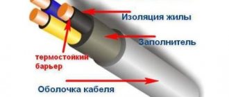
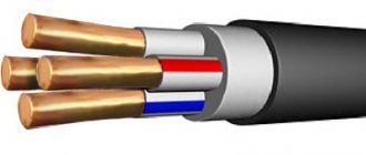
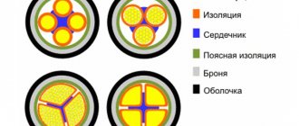
A cable of this type consists of copper or aluminum current-carrying conductors in the amount of 1-5 pieces (see B in Fig. 1). Depending on the design, they can be monolithic or multi-core.
VVG cable design
Each of the cores is covered with an insulating sheath (C) based on polyvinyl chloride (hereinafter referred to as PVC). A special dye has been added to its composition, which allows you to identify the wires in accordance with the color marking. The current-carrying parts of the cable are placed in a common PVC sheath (A).
This design is typical for all varieties, with the exception of the VVGP version and its modifications, which have a flat rather than round shape.
Cable VVG-P
