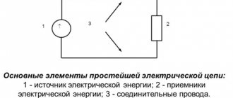
Classification of electrical networks by type of current
Based on the type of current, electrical networks are traditionally divided into two types - AC and DC networks.
The most common are AC networks. Direct current is most often used to power electrified transport; direct current power supply lines are built for it. In some individual cases at industrial enterprises there is a need to build direct current power supply systems, for example, for the electrolysis of solutions or electrometallurgy, as well as in the presence of direct current electric drives.
Recently, high-voltage direct current (HVDC) power lines, which are actively used to transmit electricity from alternative energy power plants, have attracted increasing interest from designers. The advantage of such systems is their greater efficiency, the possibility of parallel operation with different direct current lines (for example, alternating current power lines with frequencies of 50 Hz and 60 Hz cannot be run in parallel), as well as the absence of the need to synchronize power line frequencies.
Classification of power lines
According to the same rules of MPTEP, power lines are divided into overhead and cable. But it should be noted that power lines also transmit high-frequency signals, which are used to transmit telemetric data, for dispatch control of various industries, for emergency automation signals and relay protection. According to statistics, 60,000 high-frequency channels today pass through power lines. Let's face it, the figure is significant.
Classification of electrical networks by voltage
Based on voltage, electrical networks are classically divided into two types - up to 1000 V and above 1000 V. To avoid confusion and ease of operation of serial electrical products in AC installations, the following voltage standards have been adopted:
- Up to 1000 V – 127 V, 220 V, 380 V, 660 V;
- Above 1000 V – 3 kV, 6 kV, 10 kV, 20 kV, 35 kV, 110 kV, 150 kV, 220 kV, 330 kV, 500 kV, 750 kV;
Under normal operating conditions, electrical receivers, depending on their purpose, allow strictly limited voltage deviations from its nominal value. To maintain voltages at a given level, it is necessary to compensate for its loss in transformers. It is for this purpose that the rated voltages of generators, as well as the secondary windings of transformers, have ratings that are 5% higher than those of electrical receivers.
For local lighting networks, low voltages can be used, namely 12 V, 24 V, 36 V.
Elements of overhead power lines
There are always conversations between specialists in which special terms relating to power lines are used. For the uninitiated in the subtleties of slang, it is quite difficult to understand this conversation. Therefore, we offer a definition of these terms.
- The route is the axis of the power transmission line, which runs along the surface of the earth.
- PC – pickets. Essentially, these are sections of the power line route. Their length depends on the terrain and the rated voltage of the route. Zero picket is the beginning of the route.
- The construction of a support is indicated by a center sign. This is the center of the support installation.
- Picketing is essentially a simple installation of pickets.
- The span is the distance between the supports, or more precisely, between their centers.
- The sag is the delta between the lowest point of the wire sag and the strictly tensioned line between the supports.
- The wire size is again the distance between the lowest point of the sag and the highest point of the engineering structures running under the wires.
- Loop or train. This is the part of the wire that connects the wires of adjacent spans on the anchor support.
Classification of electrical networks by purpose
According to their purpose, electrical networks are divided into distribution and supply.
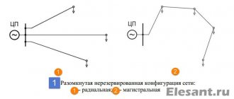
A supply line is a line that supplies power to a substation (S) or distribution point (DP) from a power center (CP) without distributing electrical energy along its length.
Distribution line - a line that supplies power to a number of transformer substations from the distribution center or central processing unit.
In networks with voltages up to 1000 V, supply lines are lines that go from transformer substations to distribution boards or points, and distribution lines are called lines that go directly from distribution boards or points to power receivers.
Below is a high voltage distribution diagram with the presence of a supply and distribution network (a)) and only a distribution network (b)):
High voltage networks are constructed in cases where the voltage source is located quite a long distance away or there are a large number of transformer substations that are significantly distant from each other, for example, when supplying electricity to large industrial enterprises or cities.
Features of dismantling electrical equipment
Work related to the dismantling of electrical equipment is considered to be of increased danger. Such work is performed in case of breakdown, failure of products or when replacing obsolete equipment with more modern models. The electrician must have permission to work under voltage and with electrical equipment. He must be able to use special equipment, tools and instrumentation.
The work is performed in the following sequence:
- disconnect the product from the power source;
- disconnected from the grounding circuit;
- removed from the base by unscrewing the fasteners.
The technology of dismantling, as well as installation, depends on the design of the electrical equipment. Typically, instructions for dismantling electrical equipment are specified in the operating instructions that the manufacturer encloses with the product, and which the enterprise or institution must keep until written off.
Classification of electrical networks according to the principle of construction
According to the principle of construction, electrical networks are divided into closed and open.
An open network is a set of open lines receiving power from one common power source IP on one side (figure below):
Its main disadvantage is the interruption of power to all electrical receivers in the area where the outage occurred due to a line break.
In a closed system, the opposite is true - power comes from two power supply sources and if the main line breaks anywhere, the power supply to the electrical receivers will not stop. The simplest diagram of a closed network is shown below:
For example, in the event of a line break at point K, power receivers 1,2,3,4 will receive power from the upper line, and 5,6,7,8 from the bottom. Depending on the requirements for reliability of power supply, closed systems may have one or more power sources. Below is an example of a circuit with two-way power supply:
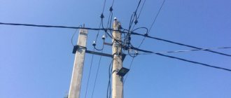
Overhead power lines
Overhead power lines, usually designated by the letters “VL”, are devices that are located in the open air. That is, the wires themselves are laid through the air and fixed to special fittings (brackets, insulators). Moreover, their installation can be carried out on poles, bridges, and overpasses. It is not necessary to consider “overhead lines” those lines that are laid only along high-voltage poles.
What is included in overhead power lines:
- The main thing is the wires.
- Crossbars, with the help of which conditions are created to prevent the wires from coming into contact with other elements of the supports.
- Insulators.
- The supports themselves.
- Ground loop.
- Lightning rods.
- Arresters.
That is, a power line is not just wires and supports; as you can see, it is a fairly impressive list of various elements, each of which carries its own specific loads. You can also add fiber optic cables and auxiliary equipment to them. Of course, if high-frequency communication channels are carried along power line supports.
The construction of a power transmission line, as well as its design, plus the design features of the supports are determined by the rules for the design of electrical installations, that is, the PUE, as well as various building rules and regulations, that is, SNiP. In general, the construction of power lines is not an easy and very responsible task. Therefore, their construction is carried out by specialized organizations and companies with highly qualified specialists on staff.
Models of Shatura type supports UM-103g
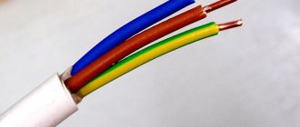
Cable power lines
Next, we move on to consider such a concept as cable power lines. Let's start with the fact that these are not bare wires that are used in overhead power lines, these are cables enclosed in insulation. Typically, cable power lines are several lines installed next to each other in a parallel direction. The cable length is not enough for this, so couplings are installed between sections. By the way, you can often find oil-filled cable power lines, so such networks are often equipped with special low-fill equipment and an alarm system that responds to oil pressure inside the cable.
If we talk about the classification of cable lines, they are identical to the classification of overhead lines. There are distinctive features, but not many of them. Basically, these two categories differ from each other in the method of installation, as well as design features. For example, according to the type of installation, cable power lines are divided into underground, underwater and by structure.
cable line
The first two positions are clear, but what applies to the “structures” position?
- Cable tunnels. These are special closed corridors in which cables are laid along installed support structures. You can walk freely in such tunnels while installing, repairing and maintaining power lines.
- Cable channels. Most often they are buried or partially buried channels. They can be laid in the ground, under the floor base, or under ceilings. These are small canals in which it is impossible to walk. To check or install the cable, you will have to dismantle the ceiling.
- Cable mine. This is a vertical corridor with a rectangular cross-section. The shaft can be walk-through, that is, with the ability for a person to fit into it, for which it is equipped with a ladder. Or impassable. In this case, you can get to the cable line only by removing one of the walls of the structure.
- Cable floor. This is a technical space, usually 1.8 m high, equipped with floor slabs at the bottom and top.
- Cable power lines can also be laid in the gap between the floor slabs and the floor of the room.
- A cable block is a complex structure consisting of laying pipes and several wells.
- A chamber is an underground structure covered on top with reinforced concrete or a slab. In such a chamber, sections of cable power lines are connected with couplings.
- An overpass is a horizontal or inclined open structure. It can be above-ground or above-ground, walk-through or impassable.
- A gallery is practically the same as an overpass, only closed.
And the last classification in cable power lines is the type of insulation. In principle, there are two main types: solid insulation and liquid. The first includes insulating braids made of polymers (polyvinyl chloride, cross-linked polyethylene, ethylene-propylene rubber), as well as other types, for example, oiled paper, rubber-paper braid. Liquid insulators include petroleum oil. There are other types of insulation, for example, special gases or other types of solid materials. But they are used very rarely today.
D.C
The second way to transmit electric current to the consumer is direct current. Such a current is rectified. It is found in batteries, batteries, chargers. This current is still supplied to consumers in some countries, but in very small quantities. It is produced by solar panels. Direct current can be supplied through existing power lines and underground cables. The advantages of such a transfer are the following:
- There is no loss of power with distance. There is no need to increase the voltage at the power plant.
- Static stability has no effect on transmission and distribution.
- No need to configure frequency synchronization.
- Voltage can be transmitted through just one line with one contact wire.
- No influence of electromagnetic radiation.
- Minimum reactive power.
Direct current is not supplied to the consumer only because of the huge cost of equipment for power plants.
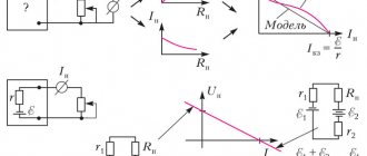
The conductivity of the electric current and the percentage of overestimation at the beginning of transmission largely depend on the resistance of the power line itself. The resistance, and thus the load, can be reduced by cooling to an ultra-low temperature. This would help increase the distance for energy transmission and significantly reduce losses. Today there is no technology for reducing the temperature of a power line. This technology is extremely expensive and requires major design changes. But in the regions of the far north, this method works quite well and greatly underestimates the percentage of power transfer and losses due to distance.