Capacitance of the capacitor
Definition
Electric capacitance is a characteristic of a conductor, a measure of its ability to accumulate electrical charge.
Electrical capacitance is denoted as C. The unit of measurement for electrical capacitance is Farad (F).
The electrical capacity of a capacitor is determined by the formula:
C=ε0εSd..
- ε0 is the dielectric constant equal to 8.85∙10–12 C2/(N∙m2);
- ε is the dielectric constant of the medium;
- S (m2) is the area of each plate.
Attention! An air capacitor has a dielectric constant of 1.
The relationship between the capacitance of a capacitor, charge and voltage is determined by the formulas:
C=QU..=qU..
Important! The electrical capacity of a capacitor depends only on the area of its plates, the distance between them and the dielectric constant of the medium. This value does not depend on charge and voltage.
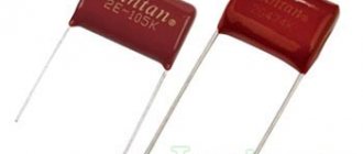
Capacitor markings
On the body of each capacitor there is a special marking - a letter and a number. Compared to resistors, capacitor markings indicating capacitance and capacitance deviation code are quite complex and varied. Sometimes the designations are written in capital letters - MF (microfarads), fd - farads. There are also positive and negative symbols on the housing to help determine the polarity of the capacitor.
Ways to designate a capacitor
The unit of measurement for the capacitance of a capacitor is the farad, so the letter Ф or F must be present on the body of the element:
- 1 millifarad = 10-3 farads = 1mF;
- 1 microfarad = 10-6 farads = 1 µF;
- 1 nanofarad = 10-9 farads = 1 nF;
- 1 picofarad = 10-12 farads = 1 pF.
If the element is not marked with a nominal value, then the integer value indicates that the capacity is indicated in picofarads. On the case, the capacity is indicated with a deviation; if the letter J is indicated, then the deviation range is less than 5%, the letter M is 20%.
Imported capacitor code
Imported devices, just like Russian ones, are marked in accordance with international standards. This regulatory document requires the application of a three-digit code. The first two digits indicate the capacitance in picofarads. The third digit indicates the number of zeros, for example, if the capacitance is less than 1 picofarad, the digit will look like “0”.
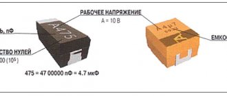
Code for surface mount capacitors
The marking of electrolytic SMD capacitors consists of capacitance and operating voltage. For example, 108V, where an electrical capacity of 10 pF and an operating voltage of 8 Volts are encoded. The plus sign is next to the stripe. There are three main encoding methods: a code of two or three characters (letters or numbers) that indicate the operating voltage and rated capacity. Indicators are indicated by a letter, and the number is a multiplier; four characters indicating voltage and rated capacitance. The first letter is the operating voltage, the next characters are the capacity in picofarads, the last digit is the number of zeros;
if the body area is large, the code is placed on two lines. The top line is the capacitance rating, the bottom line is the operating voltage.
Capacitor energy
Capacitor energy formula
The energy of a capacitor is related to its electrical capacity and is calculated using the following formulas:
We=q22C..=CU22.
Hints for problems
| Capacitor disconnected from source | q = q′ |
| Capacitor connected to source | U = U′ |
| The amount of heat and energy of the capacitor | Q = ∆We |
Example No. 1. Calculate the electrical capacity of a flat air capacitor with square plates with a side of 10 cm, located at a distance of 1 mm from each other. Round your answer to tenths.
10 cm = 0.1 m
1 mm = 0.001 m
Since there is air between the plates of the capacitor, we take the dielectric constant of the medium as unity.
The area of a square plate is equal to the square of its side:
S = a2
Flat capacitor.
So, the simplest capacitor consists of two flat conducting plates located parallel to each other and separated by a dielectric layer. Moreover, the distance between the plates should be much smaller than, in fact, the dimensions of the plates:
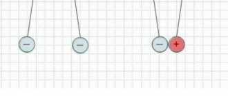
Such a device is called a flat capacitor , and the plates are called capacitor plates . It is worth clarifying that here we are considering an already charged capacitor (we will study the charging process itself a little later), that is, a certain charge is concentrated on the plates. Moreover, the greatest interest is in the case when the charges of the capacitor plates are identical in magnitude and opposite in sign (as in the figure).
And since the charge is concentrated on the plates, an electric field arises between them. The field of a flat capacitor is mainly concentrated between the plates, however, an electric field also arises in the surrounding space, which is called a leakage field. Very often its influence in tasks is neglected, but it should not be forgotten.
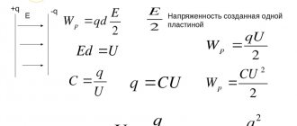
To determine the magnitude of this field, consider another schematic representation of a flat-plate capacitor:
Each of the capacitor plates individually creates an electric field:
- a positively charged plate (+q) creates a field whose strength is E_{+}
- a negatively charged plate (-q) creates a field whose strength is E_{-}
The expression for the field strength of a uniformly charged plate is as follows:
E_{pl} = \frac{\sigma}{2\varepsilon_0\thinspace\varepsilon}
Here \sigma is the surface charge density: \sigma = \frac{q}{S}, and \varepsilon is the dielectric constant of the dielectric located between the capacitor plates. Since the area of the capacitor plates is the same, as is the magnitude of the charge, then the electric field strength modules are equal to each other:
E_+ = E_- = \frac{q}{2\varepsilon_0\thinspace\varepsilon S}
But the directions of the vectors are different - inside the capacitor the vectors are directed in one direction, and outside - in the opposite direction. Thus, inside the plates the resulting field is defined as follows:
E = E_+ + E_- = \frac{q}{2\varepsilon_0\thinspace\varepsilon S} + \frac{q}{2\varepsilon_0\thinspace\varepsilon S} = \frac{q}{\varepsilon_0\thinspace \varepsilon S}
Accordingly, outside the capacitor (to the left and right of the plates) the fields of the plates compensate each other and the resulting voltage is 0.
Determining the capacitance of an unknown capacitor
Method: measuring capacitance with special devices
The easiest way is to measure the capacitance using a device that has a capacitance measurement function. This is already clear, and this was already discussed at the beginning of the article and there is nothing more to add.
If you're not very comfortable with instruments, you can try putting together a simple homemade tester. You can find good schemes on the Internet (more complex, simpler, very simple).
Well, or finally fork out for a universal tester that measures capacitance up to 100,000 µF, ESR, resistance, inductance, allows you to check diodes and measure the parameters of transistors. How many times has he helped me out!
Formula
The capacitor charge current is found using the formula presented below. It is measured in farads, which is equal to a coulomb or volt.
Formula for finding the charge of a capacitor
In general, this is an element of the electrical network that accumulates and stores voltage in it. It comes in different types and sizes, for example, electrolytic, ceramic and tantalum. It consists mainly of several conductive plates with a dielectric. Its capacity depends on the size of the dielectric and the filler between the plates. Charges using electricity. The capacitor charge current can be determined using measuring instruments and a formula.
Application of capacitors in technology
It is logical to use capacitors as electrical energy storage devices. In this capacity, they cannot compete with electrochemical sources (galvanic batteries, capacitors) due to the small stored energy and fairly rapid self-discharge due to charge leakage through the dielectric. But their ability to store energy for a long period and then release it almost instantly is widely used. This property is used in flash lamps for photography or in lamps for driving lasers.
Capacitors are widely used in radio engineering and electronics. Capacitances are used as part of resonant circuits as one of the frequency-setting elements of circuits (the other element is inductance). The ability of capacitors not to pass direct current without delaying the alternating component is also used. This application is common for separating amplifier stages to eliminate the influence of the DC modes of one stage on the other. Large capacitors are used as smoothing filters in power supplies. There are also a huge number of other applications for capacitors where their properties are useful.
Processes of charging and discharging capacitors.
We've figured out the device, now let's figure out what happens if we connect a DC source to the capacitor. On circuit diagrams, a capacitor is designated as follows:
So, we have connected the capacitor plates to the poles of the DC source. What will happen?
Free electrons from the first plate of the capacitor will rush to the positive pole of the source. Because of this, there will be a lack of negatively charged particles on the plate, and it will become positively charged. At the same time, electrons from the negative pole of the current source will move to the second plate of the capacitor. As a result, an excess of electrons will appear on it, and accordingly, the plate will become negatively charged. Thus, charges of different signs are formed on the plates of the capacitor (this is exactly the case we considered in the first part of the article), which leads to the appearance of an electric field that will create a certain potential difference between the plates of the capacitor. The charging process will continue until this potential difference becomes equal to the voltage of the current source. After this, the charging process will end and the movement of electrons along the circuit will stop.
When disconnected from the source, the capacitor can retain accumulated charges for a long time. Accordingly, a charged capacitor is a source of electrical energy, which means that it can release energy into an external circuit. Let's create a simple circuit by simply connecting the capacitor plates to each other:
In this case, a capacitor discharge current will begin to flow through the circuit, and electrons will begin to move from the negatively charged plate to the positive one. As a result, the voltage across the capacitor (the potential difference between the plates) will begin to decrease. This process will end at the moment when the charges of the capacitor plates become equal to each other, accordingly, the electric field between the plates disappears and current stops flowing through the circuit. This is how the capacitor discharges, as a result of which it releases all the accumulated energy into the external circuit.
Polar and non-polar capacitors
It is very important to separate capacitors into polar and non-polar .
Oxide-based devices: electrolytic aluminum and tantalum are usually polar, which means that if their polarity is reversed, they will fail. Moreover, this failure will be accompanied by violent electrochemical reactions up to the explosion of the capacitor.
Polar capacitors are always marked. As a rule, on electrolytic capacitors, the negative terminal (cathode) is marked with a contrasting stripe on the case; for tantalum capacitors (in yellow rectangular cases), the positive terminal (anode) is marked with a stripe. If you have doubts about the marking, it is better to find the documentation for this capacitor and make sure.
Non-polar capacitors can be connected to the circuit in any direction. For example, multilayer ceramic capacitors are non-polar.
How to connect capacitors correctly?
Many novice electronics enthusiasts in the process of assembling a homemade device have a question: “How to connect capacitors correctly?”
It would seem why this is necessary, because if the circuit diagram indicates that a 47 microfarad capacitor should be installed in a given place in the circuit, then we take it and install it. But, you must admit that in the workshop of even an avid electronics engineer there may not be a capacitor with the required rating!
A similar situation may arise when repairing any device. For example, you need an electrolytic capacitor with a capacity of 1000 microfarads, but you only have two or three at hand with a capacity of 470 microfarads. Set 470 microfarads instead of the required 1000? No, this is not always acceptable. So what should we do? Go to the radio market several tens of kilometers away and buy the missing part?
How to get out of this situation? You can connect several capacitors and as a result get the capacitance we need. In electronics, there are two ways to connect capacitors: parallel and series.
In reality it looks like this:
Parallel connection Circuit diagram of parallel connection Serial connection Circuit diagram of series connection
It is also possible to combine parallel and serial connections. But in practice you are unlikely to need this.
Series connection of capacitors
If the connection of capacitors in a battery is made in the form of a chain and the plates of only the first and last capacitors are directly connected to the connection points in the circuit, then such a connection of capacitors is called serial. When connected in series, all capacitors are charged with the same amount of electricity, since only the outer plates are charged directly from the current source, and the remaining plates are charged through influence. In this case, the charge of the plate will be equal in magnitude and opposite in sign to the charge of plate 1, the charge of plate 3 will be equal in magnitude and opposite in sign to the charge of plate 2, etc.
The voltages on different capacitors will, generally speaking, be different, since charging capacitors of different capacities with the same amount of electricity always requires different voltages.
Types of capacitor connections. The smaller the capacitance of the capacitor, the greater the voltage required in order to charge this capacitor with the required amount of electricity, and vice versa.
Thus, when charging a group of capacitors connected in series, the voltages on small capacitors will be greater, and on large capacitors - less.
It will be interesting➡ What is an autotransformer?
Similar to the previous case, we can consider the entire group of capacitors connected in series as one equivalent capacitor, between the plates of which there is a voltage equal to the sum of the voltages on all capacitors of the group, and the charge of which is equal to the charge of any of the capacitors of the group. Let's take the smallest capacitor in the group. There should be the greatest tension on it. But the voltage across this capacitor is only a fraction of the total voltage that exists across the entire group of capacitors. The voltage across the entire group is greater than the voltage across the capacitor with the smallest capacitance. And from here it directly follows that the total capacitance of a group of capacitors connected in series is less than the capacitance of the smallest capacitor in the group.
A series connection of capacitors is the connection of two or more capacitors in the form of a circuit in which each individual capacitor is connected to another individual capacitor at only one point. The current (iC) charging a series capacitor circuit will be the same for all capacitors because it has only one possible path.
Due to the fact that the same current flows through all capacitors connected in series, the amount of accumulated electrical charge for each capacitor will be the same, regardless of its capacitance. This happens because the electrical charge accumulated on the plate of any capacitor must come from the plate of the adjacent capacitor. Thus, capacitors connected in series have the same electrical charge.
Worth reading: everything about electrolytic capacitors.
The right plate of the first capacitor C1 is connected to the left of the second capacitor C2, whose right plate is connected to the left of the third capacitor C3. This means that in DC mode, capacitor C2 is electrically isolated from the general circuit. As a result, the effective area of the plates is reduced to the area of the plates of the smallest capacitor. This is explained by the fact that as soon as the plates of the smallest area are filled with electric charge, this capacitor will stop passing current. As a result, the current will stop in the entire circuit, and the charging process of the remaining capacitors will also stop. With a series connection, the total distance between the plates increases to the sum of the distances between the plates of all capacitors.
Thus, the series circuit forms one large capacitor with the area of the plates of the element with the smallest capacitance, and the distance between the plates equal to the sum of all distances in the circuit. Each individual capacitor in a series circuit experiences a different voltage drop. Since capacitance is inversely proportional to voltage (C = Q/V), the smaller the capacitance of the capacitor, the greater the voltage will drop across it. Let us apply Kirchhoff's law to the voltage in a series circuit of three capacitors.
The capacitance of a capacitor is directly proportional to its charge and inversely proportional to its voltage - C = Q/V. As mentioned above, capacitors connected in series have the same electrical charge - Qtot = Q1 = Q2 = Q3. From this equation you can easily derive the formula for the total capacitance for any particular case of a series connection.
If a circuit has both a serial and parallel connection, then such a circuit is called mixed or series-parallel. However, a mixed connection can be either serial or parallel.
Types of capacitor connections.
What does a capacitor consist of?
Any capacitor consists of two or more metal plates that do not touch each other. For a more complete understanding of how all this works in a capacitor, let's imagine a pancake.
spread it with condensed milk
and put the exact same pancake on top
The condition must be met: these two pancakes must not touch each other. That is, the top pancake should lie on the condensed milk and not touch the bottom pancake. Here, I think, everything is clear. Here is a typical “pancake capacitor” :-). This is how all capacitors are designed, only thin metal plates are used instead of pancakes, and various dielectrics are used instead of condensed milk. The dielectric can be air, paper, electrolyte, mica, ceramics, and so on. Wiring is connected to each metal plate - these are the leads of the capacitor.
Schematically it all looks something like this.
As you may have noticed, due to the dielectric, the capacitor cannot conduct current. But this applies only to direct current. The capacitor passes alternating current through itself without problems with a small resistance, the value of which depends on the frequency of the current and the capacitance of the capacitor itself.
What is a capacitor
Condenser, or as people say - “conder”, is formed from the Latin “condensatus”, which means “compacted, condensed”. It is a passive radio element that has the property of retaining an electric charge on its plates, if, of course, it is charged with some kind of power source beforehand.
Roughly speaking, a capacitor can be thought of as a battery or accumulator of electrical energy. But the whole difference is that an accumulator or battery contains an EMF source, while a capacitor lacks this internal source.
Formulas for measuring capacitor voltage
The numerical indicator of voltage is equal to electromotive force. It is also defined as the capacity divided by the amount of charge, based on the formula for determining its value. According to another rule, the voltage is equal to the leakage current divided by the insulation resistance.
You might be interested in Finding out the cathode and anode
Basic formulas for calculation
In general, a capacitor is a device for accumulating electrical charge, consisting of several plate electrodes that are separated by dielectrics. The device has an electrode measured in farads. One farad is equal to one coulomb. The voltage of the device is affected by the current, the indicators of which can be calculated using the formulas described above.
Basic concepts related to electrical capacity
If a conductor receives a charge q, a potential φ arises on it. This potential depends on geometry and environment - for different conductors and conditions, the same charge will cause different potentials. But φ is always proportional to q:
φ=Cq
Coefficient C is called electrical capacitance. If we are talking about a system of several conductors (usually two), then when a charge is imparted to one conductor (plating), a potential difference or voltage U arises:
U=Cq, hence C=U/q
Capacitance can be defined as the ratio of the potential difference to the charge that caused it. The SI unit of measurement of capacitance is the Farad (formerly called Farad). 1 F = 1 V/1 C. In other words, a system has a capacity of 1 farad in which, when a charge of 1 coulomb is imparted, a potential difference of 1 volt arises. 1 Farad is a very large value. In practice, fractional values are most often used - picofarad, nanofarad, microfarad.
In practice, such a connection makes it possible to obtain a battery that can withstand a higher dielectric breakdown voltage than that of a single cell.
How is capacitor voltage measured?
The voltage is reflected on the body of the equipment and shows at what level of energy it operates. The voltage of the capacitors is measured in farads. This is a unit named after Michael Faraday. One farad is a coulomb, or charge, passed through a conductor in one second at a current of one ampere. As a rule, farads and coulombs are not used for measurement in practice, because fractional quantities are more often used - micro-, nano- and picofarads.
Measuring the charge strength of a two-terminal network
Capacitor charge. Voltage
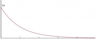
At the very beginning of the charging transition period, the voltage between the plates of the capacitor is zero. As soon as charged particles begin to appear on the plates, a voltage arises between unlike charges. The reason for this is the dielectric between the plates, which “prevents” charges with opposite signs tending to each other from moving to the other side of the capacitor.
At the initial stage of charging, the voltage rises quickly because the high current very quickly increases the number of charged particles on the plates. The more the capacitor is charged, the lower the current, and the slower the voltage rises. At the end of the transition period, the voltage on the capacitor will completely stop growing and will be equal to the voltage on the power source.
As can be seen in the graph, the capacitor current directly depends on the change in voltage.
The formula for finding the capacitor current during the transition period is:
- Ic - capacitor current
- C - Capacitance of the capacitor
- ΔVc/Δt – Change in voltage across the capacitor over a period of time
Measuring capacitance of a capacitor with a multimeter and special devices
Some multimeters have a capacitance measurement feature. Take these common models: M890D, AM-1083, DT9205A, UT139C, etc.
There are also digital capacitance meters available, such as the XC6013L or A6013L.
Using any of these devices, you can not only find out the exact capacitance of the capacitor, but also make sure that there is no short circuit between the plates or an internal break in one of the terminals.