Everyone knows that the effective voltage in the socket is 220 Volts (230 according to the new standards, but for this topic this does not really matter). This can be easily checked using a multimeter, which will measure the potential difference between the phase and the working neutral conductor. That is, under ideal conditions, the potential on the neutral wire is 0, and on the phase wire 220 Volts. In fact, everything is a little different - alternating current has a sinusoidal shape with a potential at peaks of 310 and -310 Volts (amplitude voltage). In order to see this, you need to use an oscilloscope.
Sinusoid of effective and amplitude voltage
It is clear that this material is more aimed at a simple audience, who not only do not have an oscilloscope, but probably not everyone even has a multimeter. Therefore, all examples will be taken from the Electronics Workbench environment, which is accessible to everyone.
And the first thing we need to look at is the phase voltage sine wave from the outlet. To do this, we will draw a three-phase network in the program and connect the oscilloscope to one of the phases:
As can be seen with a voltmeter reading of 219.4 Volts between one of the phases and the PEN conductor, the oscilloscope showed a sine wave with an amplitude of 309.1 Volts. This voltage value is called maximum (amplitude). And 219.4 Volts, which the voltmeter shows, is the effective voltage. It is also called root mean square or effective. And before we move on to consider this feature, let’s briefly, in simple words, go through the drawn diagram of a three-phase network and understand the nature of the sinusoid.
Let's start with the diagram:
- From left to right - three AC voltage sources with phase angles of 0, 120, 240 degrees and connected by a star.
- The 4 Ohm resistor is the grounding of the transformer neutral.
- Resistors of 0.8 ohms are the conditional resistance of the wires, depending on the cross-section of the wire and the length of the line.
- Resistors 15, 10 and 20 Ohms - load of consumers in three phases.
- An oscilloscope is connected to one of the phases, showing an amplitude of 309.1 Volts.
Now let's look at a sinusoid. Alternating voltage, in contrast to constant voltage, the graph of which is straight on an oscilloscope, continuously changes both in magnitude and direction. Moreover, these changes occur periodically, that is, they are exactly repeated at regular intervals.
Alternating voltage is generated at power plants and reaches the end consumer through step-up and step-down distribution transformers. In this case, the transformation along the path does not affect the voltage sinusoid in any way.
Alternating electric current and its characteristics
In addition to direct (time-constant) current, there is alternating current, which changes its magnitude and direction over time.
Electricity generators, including automobile ones, produce alternating current, which is then converted to direct current.
As a rule, alternating current changes over time according to a sinusoidal law. To describe it, there are additional parameters - frequency and amplitude.
Figure 10. Current strength
Frequency is a quantity that shows how many complete oscillations a current (or voltage) makes per second. Frequency is measured in Hertz (one Hertz is equal to one vibration per second).
| Table 6. Frequency units | |||||||||||||||||||||||||||||||||||
| To determine it, you can use a special device - a frequency meter, but in practice they usually use an oscilloscope, which can show not only the frequency, but also the shape of the signal. Associated with frequency is another parameter called period. A period is the time it takes to complete one complete oscillation. The period is measured in seconds.
| |||||||||||||||||||||||||||||||||||
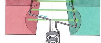
Three-phase alternator operation
Let's take a simplified look at the operation of a three-phase alternating current generator. The stator windings (phases A, B and C) of the generator are located at an angle of 120 degrees relative to each other. A rotating rotor with a magnet induces periodically changing EMF in the stator windings. It looks like this:
This rotation occurs at a frequency of 50 revolutions per second, that is, at a frequency of 50 Hertz. This means that electrons move within 1 second 50 times in one direction (positive half-cycle of a sine wave), and 50 times in the opposite direction (negative half-cycle), passing through zero value 100 times. It turns out that, for example, an ordinary incandescent lamp, connected to the network with such a frequency, will fade and flash approximately 100 times per second, but we do not notice this due to the peculiarities of our vision.
Oscillations in a resonant circuit
Electromagnetic oscillations in a circuit are one of the complex topics of the Unified State Exam. Energy passes from one form to another and is concentrated either in a capacitor or in a coil. The period of energy oscillations is half as long as the period of oscillations in the circuit (energy oscillates at double frequency).
Problem 1. An oscillatory circuit consists of an inductor and two identical capacitors connected in parallel. The period of natural oscillations in the circuit is μs. What will the period be equal to if the capacitors are connected in series?
The circuit capacitance is equal to , since the capacitors are connected in parallel. Then the period of oscillation:
Now, if we connect the capacitors in series, the capacitance will be equal to
Then
That is, the radical expression became 4 times smaller, which means the period became half as long.
Answer: mks.
Problem 2. In an oscillating circuit, the capacitance of the capacitor is μF, the inductance of the coil is H, the amplitude of the voltage on capacitor B. At some point in time, the voltage on capacitor B. Find the energy of the magnetic field at this moment. The voltage amplitude allows us to find the total energy:
Since the voltage on the capacitor at some point in time is 1 V, then at this moment its energy is equal to
Therefore, the magnetic field energy is equal to
Answer: µJ
Problem 3. What is the period of free electrical oscillations in the circuit if the maximum charge of the capacitor is Cl, and the maximum current in the circuit is A?
The total field energy is
Where
Then the period is
Answer: c.
Problem 4. An oscillatory circuit consists of a capacitor with a capacitance of pF and an inductor of mH (see figure). What is the amplitude of current oscillations if the amplitude of voltage oscillations is V?
To problem 4
Let's determine the angular frequency:
The current can be found using the formula:
Answer: 0.12 A Problem 5. An oscillating circuit consists of a capacitor with a capacity of 1 μF and an inductor of 4 H. The amplitude of oscillations of the capacitor charge is 100 µC. Write an equation for the voltage across the capacitor versus time.
General view of voltage versus time
That is, you need to determine the angular frequency and voltage amplitude.
The total field energy is
Where
Then
We record the dependence of voltage on time:
Problem 6. Two capacitors μF, μF and an inductor Hn are connected according to the circuit (see figure). At the initial moment, the switch in the capacitor circuit is open, the capacitor is not charged, there is no current in the coil, although the capacitor is charged to voltage B. What is the amplitude of the current in the coil during steady oscillations after the switch is closed?
To problem 6
The capacitor has accumulated charge, which it will “share” with the capacitor. The “division” will happen in such a way that
But the voltage across the capacitors is the same:
Then
Where:
That is .
Determine the current:
The capacitance of two capacitors connected in parallel is equal to μF.
Answer: 0.01 A. Problem 7. Based on the conditions of the previous problem, determine the period of change in the energy of the magnetic field of the coil. It is half the oscillation period.
Answer: c Problem 8. A capacitor with a capacity of 1 μF was charged to a maximum charge of 4 μC and shorted to a coil with an inductance of 0.12 H. Neglecting the active resistance of the connecting wires of the circuit, determine what the instantaneous value of the current in the circuit will be at the moment when the energy of the circuit is distributed between the electric and magnetic fields in the ratio .
Let's determine the voltage amplitude:
The total field energy is
Where
Answer: 0.01 A
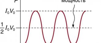
Determination of effective voltage
Now directly about why there was a transition from the maximum, amplitude voltage value of 310 Volts to the current 220 Volts. The answer can be found in the definition itself.
The effective (effective or root mean square) voltage value is the direct current voltage that, on the same resistive load, will produce the same power as the measured alternating voltage . Accordingly, the effective value of current is the value of direct current that, when passing through a resistive load, will release the same power as when passing the measured current.
It can be formulated a little differently. The effective value of an alternating current is equal to the value of a direct current that, in a time equal to one period of the alternating current, will produce the same work (thermal or electrodynamic effect) as the alternating current in question.
The general formula for calculating the effective voltage of an arbitrary shape is as follows: