Overcurrent protection with start (blocking) by voltage
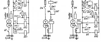
From the protection diagram presented in Figure 3.8 it can be seen that the protection will operate to turn off only after the minimum voltage relay is triggered.
To ensure reliable operation of the protection for all types of phase-to-phase and single-phase short circuits. Three minimum voltage relays 1 are installed, connected to the line voltage of the network, and one minimum voltage relay 2 reacts to the appearance of a zero-sequence voltage.
Figure 3.8 – Overcurrent protection circuit with minimum voltage blocking.
In networks with an isolated neutral, the current part of the overcurrent circuit with voltage triggering is two-phase. As for the voltage relay, the circuit is 3-phase to ensure reliable operation with 2-phase short-circuits, and a voltage relay that responds to the zero sequence is not installed, since the protection should only operate in case of inter-phase short-circuits.
The tripping current of the overcurrent protection with voltage starting is adjusted not from the maximum load current of the line, but from the normal load current In. norms, which is usually 1.52.0 times less than In. max., as a result of which the sensitivity of protection during short-circuit sharply increases.
The protection response voltage is selected based on the following conditions:
Voltage relays should not operate (close contacts) at the minimum operating voltage:
Uс.з. Ukb and is usually taken equal to 15-20% of the maximum voltage at the relay terminals for single-phase short circuits.
Directional current protection
To ensure selectivity of the action of maximum current protection in ring networks with one-way and radial networks with two-way power supply, the starting protection element is made in the form of two relays - a current relay and a power direction relay, the contacts of which are connected in series. The power direction relay closes its contact when the current direction is positive. We agreed to consider the direction of the current from the busbars to the line to be the positive direction of the current. Let's consider the principle of operation of current directional protection using the example of a single-line diagram
If a short circuit occurs on the line, t.K 1
, current relay
KA 1
and power relay
KW 1
and the protection is started.
If there is a short circuit outside the line, point . K 2
, the current is directed from the line to the busbars, the power relay does not work and blocks the protection. The introduction of a response delay ensures that the selectivity requirement is met.
The angle φ Р
= - α,
at which the torque is maximum, is called
the angle of maximum sensitivity φ MP
.
The angle α,
which determines the shift of the current vector in the voltage winding relative to the applied voltage, is called
the internal shift angle of the relay
.
Depending on the value of the internal shift angle, the relay characteristic changes its position in the coordinate plane. When α = 90
the relay is called
a reactive power relay
or sinusoidal;
at α = 0
-
active power
relay or
cosine
.
At intermediate values of the angle, the relay reacts to both components of power and is called a mixed-type relay.
These relays are most common in relay protection circuits. The internal shift angle can be changed by including active or capacitive reactance in the relay voltage winding circuit.
The sign of the torque changes when the direction of the current in the primary circuit changes. So, with a short circuit at point K 1
(Fig. 24),
the moment is positive, and with a short circuit at point
K 2
, it is negative.
Relay protection schemes take advantage of the relay's ability to sense the direction of current, which is why such relays are called power direction relays.
Semiconductor power relays, compared to induction ones, have lower power consumption, are more sensitive and accurate, and require lower operating costs.
Calculation of parameters consists of selecting the operating current, time delay and sensitivity assessment.
Selecting the operating current.
The tripping current of current directional protections is selected in the same way as for conventional maximum current protections according to the conditions of detuning from maximum load conditions. In this case, detuning is carried out from currents directed from the busbars into the line.
Choice of time delays.
The selection of time delays is made according to the counter-step principle, the application of which is shown in
Fig.
The arrows in the figure show the direction of the current at which the starting protection elements are triggered. In the event of a short circuit at point K 1
the starting elements of protection
1, 3, 5 , 6 .
The furthest protection from the power supply in this mode is protection
5 ,
so it is accepted. For other protections
; — the larger of two values is selected;
; ; — the greater of two values is selected.
In case of a short circuit at point K 2
protection triggers
1, 2, 4, 6 .
The furthest protection from the power supply in this mode is protection
2 ,
so it is accepted. For other protections
Overcurrent protection time delay
To find it, the following calculation is carried out. The operating time of the first protection during a short circuit is determined:
T1=tп1+to1+tв1,
Where:
- T1 – required time,
- tп1 – shutter speed error,
- to1 – switch off time,
- tв1 – delay time for this relay.
The second protection will not work provided that the holding time for it is greater than T1, i.e. tв2>T1.
Tв2=Т1+tп2+tз,
Where:
- tп2 – error of the second relay,
- tз – spare time.
Thus, the stage will be equal to T=tв2-tв1=tп1+tо1+tп2+tз (for an independent time-current characteristic).
Overcurrent protection circuits
Several design options are used, differing in design.
Three-phase overcurrent protection circuit on direct operating current
Three-phase design
The main unit includes two relays: time and start. An indicator relay and another additional one are also used, installed when the temporary relay is unable to close the shutdown coil circuit.
Two-phase overcurrent protection circuits on direct operating current
They are used when it is necessary for the system to turn on only when there is a short circuit between phases. There are schemes with a single relay and with a pair.
Dual relay circuit
Its advantage is its response to any interphase short circuits. The downside is less susceptibility for two-phase faults behind the transformer. You can double it by installing a third relay. The circuit is mainly used for structures with an insulated neutral - short circuits that occur in them occur only between phases. It can be used with solid grounding, but then to prevent a single-phase short circuit, an additional structure is installed that is triggered by a zero-sequence current.
Single-relay MTZ circuit
The advantage of the scheme is its ease of design. Disadvantages - least high sensitivity, failure to operate with some types of two-phase faults.
Differences from current cut-off
Logical bus protection
The MTZ uses time relays that make it possible to ignore voltage surges, which is impossible with cutoff (which is triggered not only during a short circuit episode, but also when the current increases of any other nature and duration). In addition, the use of the shut-off mechanism requires operator intervention to restore normal system operation. The relays themselves return to their original state when the cause of the opening is eliminated.
MTZ lines 6-35 kV
I have already considered MTZ, but repetition is the mother of learning. Time-delay overcurrent protection acts as the first stage of three-stage line protection. To make the calculation, it is necessary to calculate the protection operation current, setting current, time delay and differentiate from neighboring protections.
1) At the first stage, we determine the protection operation current, taking into account self-starting currents and other overcurrents that flow during the elimination of a short circuit on the previous element:
in this formula we have the following components:
Is.z.
— current of protection 2РЗ, the value that we determine
kn
— reliability factor, which in fact can be considered rather as a detuning factor for increasing the set value; for microprocessor ones it is 1.05-1.1, for electromechanical ones it is 1.1-1.4.
kszp
— self-starting coefficient, its meaning is that during a short circuit the voltage drops and the motors self-start. If there are no 6(10) kV motors, then the coefficient is assumed to be 1.1-1.3. If there is a load, then the calculation is made under the condition of self-start of the electric motor from a completely inhibited state. The self-starting coefficient is defined as the ratio of the calculated self-starting current to the maximum operating current. That is, knowing the self-starting current, you may not know the maximum operating current, although without this knowledge it will not be possible to calculate the self-starting current - in general, it will not be possible to shorten the formula much.
kv
— return coefficient of maximum current relays; for digital - 0.96, for mechanics - 0.65-0.9 (depending on the type of relay)
Iwork.max.
— the maximum operating current, taking into account possible overloads, can be obtained from dispatchers, if you have a telephone number and authority. For transformers up to 630 kVA = 1.6-1.8*Inom, for transformers of two-transformer substations 110kV = 1.4-1.6*Inom.
2) At the second stage, we determine the protection operation current, coordinating the protections L1 and L2:
Is.s.s.s.
— tripping current of protection 2РЗ
kn.s.
— coordination reliability coefficient, the value of this coefficient is from 1.1 to 1.4. For relay RT-40 - 1.1, for RTV - 1.3...1.4.
kр
— current distribution coefficient, with one power source, is equal to unity. If there are several sources, then it is calculated through equivalent circuits and element resistances.
First sum in brackets
- this is the largest of the geometric sums of the overcurrent protection currents of parallel operating previous elements.
The second sum
is the geometric sum of the maximum values of the operating currents of the previous elements, except for those with which coordination occurs.
3) At the third stage, we select the largest of the currents determined by conditions 1) and 2) and calculate the current setting:
kсх
- circuit coefficient, this coefficient shows how many times the current in the relay is greater than the current I2 of the current transformer in symmetrical normal operation; when switched on to phase currents (star or open star) it is equal to 1, when switched on to the phase current difference (triangle) it is 1.73.
nt
— transformation ratio of the current transformer.
4) Next, the sensitivity coefficient is determined, which must be greater than or equal to the value specified in the PUE.
The ratio of the minimum current flowing in the relay, under the least favorable operating conditions, to the relay operating current (set). For MTZ, the value of kch must be at least 1.5 for a short-circuit in the main protection zone and at least 1.2 for a short-circuit in distant redundancy zones.
5) Determine the time setting
The meaning of the time settings is as follows: if we have a short circuit as in the figure above, then switch L1 (located closer to the short circuit) must first turn off; this is necessary in order to leave undamaged sections of the system in operation.
That is, tс.2рз=tс.1рз+dt
, where delta t is the selectivity level. This value depends on the speed of the protection (in particular, the accuracy of the time relay) and the on-off time of the switches.
If the previous RP is a current cut-off or the RP is made using electronic (semiconductor) relays, dt can be taken as 0.3 s. If electromechanical relays are used in the relay protection, then dt can be 0.5...1.0. For different relays this value can reach several seconds.
As was written above, a feature of MTZ is the accumulation of time delays from element to element. And the larger the dt value, the larger the remote setpoint will be. To solve this problem, digital relays (dt=0.15...0.2s) and identical switches should be installed. After all, if the switches are of the same type, then the response time is the same for all. And if it is small, then the total value will be small.
In general, the choice of MTZ consists of three stages:
- failure of 2RZ during overcurrents in post-emergency modes
- coordination of 2РЗ with 1РЗ
- ensuring sensitivity during short circuit at the end of L1 (working zone) and at the end of L2 (long-range backup zone)
Operating principle
MTZ is a type of power network protection mechanism using a relay, used when there is a threat of a short circuit on a certain section of the electrical circuit.
The operating principle of overcurrent protection is quite similar to that of the cut-off mechanism. If, when using the latter, the current is cut off immediately, then when using MTZ, the shutdown occurs after a certain period of time. It's called time delay. The value it takes is determined by the proximity of the incident to the food provider. The further away the segment is, the lower the number. The value by which the indicator of the nearby section differs from that of the remote section (selectivity level) describes the period after which the protection is activated in the near section (disabling the far section as well), if it was not activated in the distant section where the short circuit incident occurred.
Important! The step indicator must be kept small so that the system has time to turn on before the incident causes serious damage to the electrical network.
Types of overcurrent protection
Arc protection
Based on operating conditions in a particular electrical network, you can choose one of four types of system.
MTZ with current-independent time delay
The delay parameter here is unchanged, the activation period depends only on the selectivity stage: at each subsequent segment, the time increases by this amount.
Overcurrent protection with current-dependent time delay
The shutter speed is calculated using a nonlinear formula. The parameter depends on the current value in the windings. Used in systems where protection from excess loads is of particular importance for safety.
MTZ with limited current-dependent time delay
Here two components are combined: a current-independent part and a dependent one, and in the latter the time-current characteristic has the form of a hyperbola. The greater the overload, the flatter the graphical representation. This installation is used in high-power electric motors.
MTZ with start (blocking) from a minimum voltage relay
Here, the initiator of contact opening is the potential difference. The setting is tied to the voltage drop below a certain limit.
Examples and description of MT circuits
Different types of circuitry are used to protect different components in single-end power networks.
Single-relay on operative current
Circuit with one relay on operative current
A start relay is used that responds to changes in the phase potential difference. The advantages are its simplicity and low resource consumption - only one relay and two cables are needed. The disadvantages are low susceptibility and the fact that if some element fails, the line fragment loses protection. The circuit is suitable for networks with voltages up to 10 kV.
Two-relay on operative current
Circuit with a pair of relays
This circuit, like the previous one, protects power lines from the consequences of a short circuit between phases. The chains in it form a truncated star. It is reliable, but, like the previous one, not very sensitive.
Three-relay
This is the most reliable and the only circuit suitable for structures with a tightly grounded neutral.
Although current cutting is more effective in preventing short circuits, the use of the reviewed method is more suitable for protecting branched power lines. For maximum efficiency, it is necessary to correctly set the settings in the circuit.
Selecting the overcurrent protection current
The choice is made with the expectation that the installation will reliably operate under damaging influences, but does not show activity during short shocks (for example, when the electric motor starts) or high load current. Differentiating the latter from the situation where the defense should be activated is the main task. Also, the installation should not be overly sensitive, otherwise the circuit will turn off when it is not needed.
The following conditions must be met:
- the relays should not be activated by the load current, therefore the parameter at which the overcurrent protection is triggered must be greater than the maximum load indicator;
- the return current of the relay must exceed the load value flowing through the protection after the end of the circuit - this is necessary to return the relay to its initial position.