2.8. Single-phase earth fault protection
Protection against single-phase earth faults can be implemented based on two different approaches [8]. Firstly, by general (non-selective) monitoring of the network insulation state relative to ground. Secondly, selectively acting means that detect ground faults at individual connections.
General monitoring of the insulation condition and detection of single-phase earth faults are usually based on continuous measurement of the zero-sequence voltage in the controlled electrical network. In this case, only the fact that a short circuit has occurred is revealed. But it is impossible to determine from the zero-sequence voltage which connection the damage occurred at. Therefore, you have to turn them off one by one. When the damaged connection is disconnected, the zero-sequence voltage in the network decreases to the background level. This sign is used when searching for damage.
In accordance with the definition of symmetrical components, the zero-sequence voltage is represented as follows:
Here ĖA0, ĖB0, ĖC0 are the emf vectors. phases A, B, C, respectively, relative to ground.
It follows that in normal symmetrical mode, when the network neutral potential is zero, and the modules of the vectors ĖA0, ĖB0, ĖC0 are equal to the corresponding modules of the phase emf vectors, the zero-sequence voltage in the network Ú = 0.
When phase C is shorted to ground
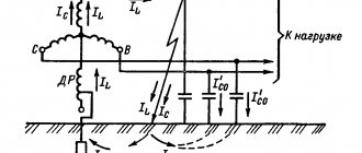
As you can see, with a metal phase-to-ground fault, the zero-sequence voltage modulus is equal to the phase emf modulus. networks. Consequently, the effective value of the zero-sequence voltage is equal to the effective value of the phase voltage. The integral value of this voltage can be controlled directly using a relay, which is connected to the network neutral through a VT (Fig. 2.32).
To control the zero-sequence voltage, a zero-sequence voltage filter is often used, built on the basis of a three-phase VT, the secondary windings of which are connected according to an open delta circuit (Fig. 2.33) [8]. To measure the current zero-sequence voltage values, a PV voltmeter is also connected in parallel to the KV voltage relay coil (see Fig. 2.32 and Fig. 2.33).
The value of the response voltage (on the scale of primary values) is selected according to the condition of detuning from the maximum possible zero-sequence voltage that occurs in the controlled network in its normal modes:
UСЗ > U0HP MAX.
Here UСЗ is the effective (primary) value of the protection response voltage; U0HP MAX is the highest possible effective (primary) value of the zero-sequence voltage in the controlled network under normal conditions.
The voltage value U0HP MAX is determined by the maximum permissible neutral potential (UN MAX), which, in turn, is determined by the degree of asymmetry of the network phase capacitances relative to the ground:
UN MAX = (5 - 10) % UФ NOM,
where UФ NOM is the rated phase voltage of the network.
In addition, zero-sequence voltage can occur in the network as a manifestation of ground faults in adjacent (external) networks and errors in the measurement path. As a result of the combined influence of these two factors, it can amount to 3–5% of UF NOM.
Taking into account the possibility of the appearance of a zero-sequence voltage under the influence of all the noted factors, as a rule, choose:
UСЗ = 0.15UФ NOM.
The relay response voltage is determined taking into account the VT transformation ratio (kTN):
UCP = UСЗ / kТН.
With a standard value of the maximum output voltage of the transformer (filter) zero sequence voltage of 100 V, the relay response voltage is 15 V. This response voltage value is sometimes set without calculations, since it corresponds to the minimum possible response voltage of the RN-53/60D type relay used in protection .
The protection response time is selected based on the requirements for detuning from the action of the main (selective) protections against single-phase ground faults and can be taken in the range from 0.5 to 9 seconds.
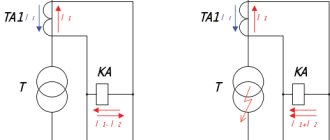
Protection against single-phase earth faults, capable of acting selectively (automatically detecting a damaged connection), can be performed on the principle of monitoring the zero-sequence current in connections. To implement this principle, a zero-sequence current transformer (filter) is installed at each connection (Fig. 2.34), in the secondary winding circuit of which a current relay coil is connected (Fig. 2.35).
In case of a single-phase ground fault at the second connection (at point K1), the zero-sequence current at the installation site of the transformer TA0-2 of this connection is determined by the total capacity of the serviceable part of the network, that is, the total capacity of the entire network, except for the own capacity of the damaged first connection. Zero-sequence currents at the installation sites of other zero-sequence transformers are determined only by the own capacitances of the connections on which these transformers are installed. For example, the zero-sequence current at the installation site TA0-1 is determined by the capacitances of the first connection. If the capacities of individual connections are approximately the same and there are quite a lot of connections, then the zero-sequence current of the damaged connection is significantly greater than that of other, undamaged connections. This flag is used to automatically detect a damaged connection. Thus, when a single-phase fault occurs at one of the connections, the protection current relay installed at this connection is triggered, and a signal is generated to disconnect the damaged connection.
The protection operation current is selected according to the condition of detuning from the own capacitive current of a ground fault of the controlled connection. In other words, the protection response current must be greater than the connection’s own capacitive current (ICC) in all normal operating modes of the controlled connection and in the event of damage to adjacent connections:
TSZ > TSPR.
The effective value of the primary protection current is determined as follows:
ISZ = kZ kBR ISPR,
where kЗ and kBR are, respectively, the safety factor and the detuning factor from capacitive current surges in transient modes.
The value of the capacitive intrinsic current of the connection is determined in accordance with clause 1.3:
If the connection configuration can change (for example, sections of cable lines or windings of electrical machines can be connected and disconnected), then the maximum possible value is taken as the calculated capacitance value.
When implementing protection on an electromechanical element base, the safety factor is assumed to be 1.2–1.3. The second coefficient kBP can have values in the range from 2 to 5. Lower values are selected if the protection is performed on a relay type RTZ-51; medium if on RTZ-50, and large if on RT-40/0.2.
The relay operating current is determined as follows:
ICP = IСЗ/kТ0,
where kT0 is the transformation coefficient of the zero-sequence CT.
If the calculated value of the protection operation current is less than the minimum possible protection operation current (relay), then the protection operation current is taken equal to this technically achievable minimum value.
The sensitivity of the protection installed at connection number K is assessed by the value of the sensitivity coefficient:
kЧWK (IСW - IСWK) / IС3WK.
Here IСW is the total capacitive current of the entire network; IСWK is the capacitive current of the connection with number K, on which the protection is installed; IC3WK is the tripping current of the protection installed at connection K.
Some data necessary for selecting the operation parameters of protection against single-phase ground faults are given in the appendix. 9.
Example
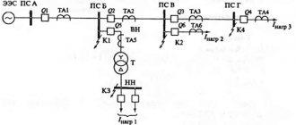
Let there be an electrical network with a 10 kV bus and connected outgoing lines (Fig. 2.36). Network parameters are given in table. 2.2. It is necessary to determine the operation parameters of the protections installed at the first and second connections.
The tripping current of the protection installed at the first connection (power supply to the electric motor) is determined as follows:
IC3W1 = k3 kBR IСW1.
The following values of the coefficients are accepted (for implementation on relays of type RTZ-51 and zero-sequence TTs of type TZLM): k3 = 1.2; kBR = 2.5.
The capacitive current of the first connection is determined by the total capacitance of the cable line and the stator winding of the electric motor:
Here CW1 = 0.047 μF is the capacitance of cable line W1, the value of which is obtained by multiplying the specific capacitance of the cable [9] by the length of the line (0.2 km); cm = 0.085 µF - capacitance of the stator windings of the electric motor (Table A9.1).
Table 2.2
If the electrical network under consideration contains large electric motors whose phase capacitances are unknown, then the approximate value of the capacitive current component (CCC), determined by the electric motor windings (in the event of an external ground fault), can be obtained using empirical formulas [5]:
IСМ ≈ 0.017 × SНМ (at rated voltage 6 kV);
IСМ ≈ 0.03 × SНМ (at rated voltage 10 kV).
Here SНМ = РНМ/(cos φН × ηН) is the total rated power of the electric motor (MVA); RNM - rated active power of the electric motor (MW); cos φН × ηН - rated power factor and rated efficiency. electric motor accordingly.
Primary protection current:
ISW W1 = 1.2 × 2.5 × 0.7 = 2.1 A.
Protection sensitivity factor:
kЧW1 = (ICW − IСw1)/IСЗW1 = (27.4 - 0.7) / 2.1 = 12.7 > 1.25.
The requirements for protection sensitivity are met.
The tripping current of the protection installed at the second connection (main line, the length of which can vary) is determined as follows:
ICЗW2 kЗ kBR ICW2.
Coefficient values (for implementation on relays of type RTZ-51 and zero-sequence TTs of type TZLM): kЗ = 1.2; kBR = 2.5.
The capacitive current of the second connection is determined by the total capacitance of individual sections of the cable line:
Here CW2.1 = 0.17 µF; CW2.2 = 0.23 µF; CW2.3 = 0.24 μF - capacitance of individual sections of the cable line W2, the values of which are obtained by multiplying the specific cable capacitance by the length of the line section [9].
Then the primary protection current is:
ICЗW2 = 1.2 × 2.5 × 3.5 = 10.5 A.
Protection sensitivity factor:
kЧW2 = (ICW − ICW2) / IСЗW2 = (27.4 − 3.5) / 10.5 = 2.27 > 1.25
Sensitivity requirements are met.
Protection against single-phase earth faults, capable of acting selectively, in electrical networks with resistive grounding of the neutral can be performed on the principle of monitoring the zero-sequence current in the connections (as well as in networks with an isolated neutral).
The method for selecting the response parameters of protection against single-phase earth faults installed in networks of this type is determined by their characteristics.
The selection of the protection operation current (as well as protections installed in networks with an isolated neutral) is made according to the condition of detuning from the connection’s own current in the event of an external fault (this current is equal to the capacitive connection current, as in a network with an isolated neutral):
ISZ > ISPR; ISZ = kZ kBR ISPR.
However, the values of the detuning coefficient from capacitive current surges can be in the range from 1 to 1.5, which makes it possible to bring the operating currents closer to the ISPR values. This is due to the relatively low level of current inrush during external single-phase ground faults in networks with resistive neutral grounding [5].
With low-resistance neutral grounding, the active component of the current at the site of the fault and at the place where the protection is installed at the damaged connection is significantly greater than the capacitive component. The capacitive component of the current can be neglected and it can be assumed that the protection responds to the active component of the controlled current. Then the protection sensitivity coefficient can be determined as follows:
kЧWK = IRW/IСЗWК.
Here IRW = Eph /RN is the active component of the current at the place where the protection is installed on the damaged connection; Eph is the effective value of the phase emf. networks; RN is the resistance of the grounding resistor; IСЗВК is the tripping current of the protection installed at the connection with number K.
If we take into account that the current during a fault at a controlled connection in these networks is several tens of amperes (determined by the parameters of the grounding resistor), then it is possible to obtain a significantly higher sensitivity of protection against single-phase ground faults than in networks with an isolated neutral.
Example
Let there be a 10 kV electrical network (Fig. 2.37) with resistive neutral grounding. The main network parameters are given in table. 2.3. It is necessary to determine the operation parameters of the protections installed at the first and second connections, as in the previous example.
The tripping current of the protection installed at the first connection (power supply to the electric motor) is determined as follows:
IСЗW1 = kЗ kBR IСW1.
When implementing protection based on relays of the RTZ-51 type and a zero-sequence TT of the TZLM type, the following can be taken: kЗ = 1.2;
Capacitive current of the first connection, determined by the total capacitance of the cable line and the stator winding of the electric motor (Table 2.3): IСW1 = 0.7 A.
Table 2.3
Primary protection current: IСЗW1 = 1.2 × 1.25 × 0.7 = 1.05 A.
Sensitivity factor of the protection installed at the first connection:
kЧW1 = IRW/IСЗW1 = 57.8 / 1.05 = 55 > 1.25
Here IRW = EF /RN = 5.78 × 10³ / 100 = 57.8 A. The sensitivity requirements are met.
Trip current of the protection installed at the second connection:
ICЗW2 = kЗ kBR ICW2.
Here you can take the following values of the coefficients: kЗ = 1.2; kBR = 1.25. Capacitive current of the second connection (Table 2.3) IСW2 = 3.5 A.
Then the primary protection current is:
IСЗW2 = 1.2 × 1.25 × 3.5 = 5.25 A.
Protection sensitivity factor:
kЧW1 = IRW /IСЗW2 = 57.8 / 5.25 = 11 > 1.25.
Sensitivity requirements are met. Moreover, as you can see, the sensitivity of protection in a network with resistive grounding of the neutral is much higher than in a network with an isolated neutral with similar parameters.
RELAY PROTECTION Protection of power lines
Basic concepts. Relay protection (RP) is an important part of automation, with the help of which faults are detected in electrical installations and a signal is sent to turn them off or alert the personnel on duty.
Relay protection is performed using various relays that respond to current, voltage, power or other electrical parameters. Relays with electromagnetic and inductive operating principles, as well as polarized, magnetoelectric and semiconductor relays based on electronic components, have become widespread.
Relays are divided into primary and secondary, direct and indirect. Primary relays are connected directly to the protected circuit (Fig. 23.1, a), secondary relays are connected through current or voltage transformers (Fig. 23.1,6). Direct action relays act directly on the release mechanism of the circuit breaker drive mechanism (Fig. 23.2, a), and an indirect action relay supplies a signal to supply operational current (voltage) to the release coil (Fig. 23.2, b).
The relay protection set consists of triggering elements that directly and constantly monitor the state and operating mode of the protected equipment, and a logical part that selects the relay protection operating mode. Starting elements are current, voltage, power relays, etc.; The logical part mainly consists of time relays, intermediate and indicating relays. In some cases, the starting and logical parts of the relay protection are executed as one whole.
To quickly disconnect a line on which a short circuit has occurred, it is equipped with a relay protection that responds to all types of short circuits and acts to open the circuit breakers. In power supply systems, as a rule, lines operate according to a one-way power supply circuit. To protect them, overcurrent protection, current cutoff and current transverse differential protection of parallel lines are used.
Maximum current protection.
This is the simplest design and therefore the most widespread protection. It is installed at the beginning of the line on the power source side (Fig. 23.3).
When the current in the line increases above the protection operation current with a time delay t3, a signal is given to trip the circuit breaker (Fig. 23.4).
In electrical networks with ungrounded transformer neutrals, the short-circuit currents are small and the previous scheme is unsuitable for sensitivity conditions. Therefore, special protection is installed in these networks, and more often, instead of it, a special device is provided for monitoring the state of the network insulation in relation to the ground with an effect on the signal (Fig. 23.6,6).
On cable lines, protection against ground faults is carried out using special zero-sequence current transformers. The latter consists of a ring core, put on a three-core cable, and a secondary winding in the form
The greatest difficulty is in setting up differential protection against surges of magnetizing current and unbalance current during external short circuits. The protection perceives magnetizing current surges that occur when the transformer is connected to the network at idle or when the transformer is disconnected from the network as a short circuit in the protected area.
The magnetizing current during the transition period contains a significant aperiodic component, which slowly decays. To tune out magnetizing current surges, a quickly saturating transformer is installed in the protection circuit, which closes the protection in the presence of an aperiodic current component in the differential circuit.
Current cut-off. On low-power transformers, current cutoff is a cheap and effective protection. The protection consists of a current relay, for example, types RT-40, RT-80, which are connected through current transformers on the supply side of the power transformer. The relay operation current is selected so that the protection does not operate in the event of a short circuit behind the transformer;
Gas protection. This protection is installed on transformers of 1000 kVA and more; reacts to all types of damage inside the transformer tank and when oil leaks from the tank.
Gas protection is carried out using special gas relays of the float, vane or cup type, which are installed in the oil line between the transformer tank and the conservator. If there is damage inside the tank under the influence of an electric arc, the oil and insulation decompose, the resulting gases rush into the conservator, which causes the movement of the oil and the action of the gas relay. The gas relay contains two contacts. One of them reacts to slow gas release and sends a signal about a malfunction in the transformer, the other reacts to the intense movement of oil, usually observed during a short circuit, and sends a signal to turn off the transformer.
Maximum current protection. The protection is designed to disconnect the transformer in the event of an external short circuit and is at the same time a backup against internal damage. On a two-winding transformer with one-way power supply, one set of protection is installed on the power source side, which acts to disconnect all switches. Maximum current protection of transformers is carried out by voltage starting, which allows you to build protection against overload currents and increase its sensitivity.
Overload protection. Transformers allow relatively large overloads, so overload protection is carried out with an effect on the signal and consists of a current relay and a time relay. The operating current is selected from the relation
Ground fault protection. One option for such protection is to install a current transformer at the zero of the power transformer (Fig. 23.9). When the transformer windings are short-circuited to ground, current flows in the zero bus 1, and the current relay KA will operate and give a signal to turn off Q1 and Q2. The protection trip current is selected from the condition)
Protection of transformers 6—10—35/0.4—0.23 kV. They are equipped with overcurrent protection, protection against single-phase earth faults on the LV side and gas protection on transformers with a capacity of 400 kVA or more, if they are located indoors.
Protection against single-phase ground faults is carried out by an automatic circuit breaker with an overload release installed on the LV side (Fig. 23.10, a), or by a current transformer on the neutral wire with a solid connection of the transformer on the LV side (Fig. 23.10, b). Gas protection with the effect of its signal on shutdown is shown in Fig. 23.10, at.
In Fig. Figure 23.11 shows transformer protection circuits when installed on the HV side of switches: (Figure 21.11, a, b) - circuit with a direct action relay of the RTM type, which provides overcurrent protection and protection against single-phase ground faults; (Fig. 23.11, c) - protection made with an indirect action relay of the RT-80 type with a dependent characteristic.