Decoding of TRDN and fundamental differences
TRDN is a three-phase split-winding power transformer with natural oil cooling and forced air circulation. Such models are accompanied by a load adjustment mechanism, the change is ±8 x 1.5%. The transformer is used to convert high voltage electricity to low voltage distribution.
The main difference is the presence of three windings, which make it possible to obtain voltages of 35 and 10 kV. The tank is made of an oval shape; radiators are used to improve cooling. There is a special hook for installation on the upper frame. Air circulation is started by a 0.25 kilowatt engine, which is located below the radiator. Production is regulated by state standards 11677-85 and 11920-85.
Power oil transformers, voltage class 220 kV
| Product type, designation of regulatory document | Rated voltage, kV | Winding connection diagram and group | Losses, kW | Weight, kg total | ||
| VN | NN | idle move | short circuit | |||
| TDN-25000/220-U1, UHL1 STO 15352615-024-2012 | 230 | 6,6; 11,0; 38,5 | YH/D-11 | 22 | 120 | 82500 |
| TRDN-25000/220-U1, UHL1 STO 15352615-024-2012 | 230 | 6,6-6,6; 11,0-11,0 | YH/DD-11-11 | 22 | 120 | 82500 |
| TRDN- 40000/220-U1, UHL1 STO 15352615-024-2012 | 230 | 6,3-6,3; 6,6-6,6; 11,0-11,0; 11,0-6,6 | YH/DD-11-11 | 50 | 170 | 99000 |
| TRDNS- 40000/220-U1, UHL1 STO 15352615-024-2012 | 230 | 6,3-6,3; 6,6-6,6; 11,0-11,0; 11,0-6,6 | YH/DD-11-11 | 50 | 170 | 99000 |
| TDN-63000/220-U1, UHL1 STO 15352615-024-2012 | 242 | 10,5 | YH/D-11 | 45 | 265 | 120000 |
| TRDNS-63000/220-U1, UHL1 STO 15352615-024-2012 | 230 | 6,3-6,3; 6,6-6,6; 11,0-11,0; 11,0-6,6 | YH/DD-11-11 | 45 | 265 | 120000 |
| TRDN-63000/220-U1, UHL1 STO 15352615-024-2012 | 230 | 6,3-6,3; 6,6-6,6; 11,0-11,0; 11,0-6,6 | YH/DD-11-11 | 45 | 265 | 120000 |
| TRDTSN- 63000/220-U1, UHL1 STO 15352615-024-2012 | 230 | 6,3-6,3; 6,6-6,6; 11,0-11,0; 11,0-6,6 | YH/DD-11-11 | 45 | 265 | *** |
| TRDTsN-100000/220-U1, UHL1* STO 15352615-024-2012 | 230 | 11,0-11,0 | YH/DD-11-11 | 102 | 340 | *** |
| TRDTsN-160000/220-U1, UHL1 STO 15352615-024-2012 | 230 | 11,0-11,0 | YH/DD-11-11 | 155 | 500 | *** |
| TRDTsN-200000/220-U1, UHL1 STO 15352615-024-2012 | 230 | 11,0-11,0 | YH/DD-11-11 | 100 | 630 | *** |
www.transformator.com.ru
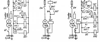
Diagram of electrical equipment and primary connections, its structure
Let's figure out what the transformer consists of, as well as what primary connections are present:
According to the standard, the technique consists of several elements:
- Input of high, medium, low voltage. They are placed on porcelain insulation, the height of which depends on the voltage class.
- The electric current in this model passes through a 110 kilovolt current transformer. The product is used for differential protection.
- Inside there are 3 windings, high, medium and low voltage, which are placed on the magnetic core. The active part is immersed in special transformer oil. Monitoring and selection is carried out in the expansion tank.
- A separate block houses the on-load tap-changer, which serves as an element for regulating voltage under load. The latter has 16 positions.
- Nearby there is a cabinet with a motor drive, as well as redundant protection.
If we consider the primary circuit of a substation with a 110 kV transformer, then in the standard version there is a short-circuiter and separator with a linear disconnector RLND-110 kV or an SF6 circuit breaker on the high side, an oil circuit breaker on the 35 kV side, and a vacuum/oil circuit breaker on the 10 kV side.
On the bus bridge there will be a tap to the auxiliary transformer. For electrical equipment of this type, a ZON is installed, which is used according to network modes or during operational switching for repairs.
Technical characteristics of NKF transformers
| Transformer type | Rated voltage, V, windings | Rated powers, VA, in accuracy classes | Maximum power***, VA | Test voltage, kV | |||||
| primary | secondary | 0,5 | 1 | 3 | VN | NN | |||
| basic | additional | ||||||||
| NKF-66-75U1* | 66 000:√ 3 | 100:√ 3 | 100 | 400 | 600 | 1200 | 2000 | 115 | 2 |
| NKF-66-75T1 | 2,2 | ||||||||
| NKF-66-76U1** | 66 000:√ 3 | 100:√ 3 | 100:3 | 400 | 600 | 1200 | 2000 | 115 | 2 |
| NKF-66-76T1 | 2,2 | ||||||||
| NKF-110-57U1* | 110 000:√ 3 | 100:√ 3 | 100 | 400 | 600 | 1200 | 2000 | 200 | 2 |
| NKF-110-57T1 | 2,2 | ||||||||
| NKF-110-57HL1 | 2 | ||||||||
| NKF-110-58U1** | 110 000:√ 3 | 100:√ 3 | 100:3 | 400 | 600 | 1200 | 2000 | 230 | 2 |
| NKF-110-58T1 | 2,2 | ||||||||
| NKF-132-73U1* | 132 000:√ 3 | 100:√ 3 | 100 | 400 | 600 | 1200 | 2000 | 230 | 2 |
| NKF-132-73T1 | 2,2 | ||||||||
| NKF-220-58U1* | 150 000:√ 3; 220 000:√ 3 | 100:√ 3 | 100 | 400 | 600 | 1200 | 2000 | 275 400 | 2 |
| NKF-220-58T1 | 2,2 | ||||||||
| NKF-220-58HL1 | 2 | ||||||||
| NKF-330-73U1* | 330 000:√ 3 | 100:√ 3 | 100 | 400 | 600 | 1200 | 2000 | 400 | 2 |
| NKF-400-65U1* | 400 000:√ 3 | 100:√ 3 | 100 | – | 500 | 1000 | 2000 | 680 | 2 |
| NKF-500-78U1*; NKF-500-78HL1 | 500 000:√ 3 | 100:√ 3 | 100 | – | 500 | 1000 | 2000 | 680 | 2 |
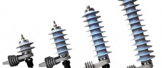
Transformers of the NKF and NKF-M series are made according to a cascade circuit. Depending on the value of the primary voltage, transformers are made at 110 kV - single-block, at 220, 330 and 500 kV - two- or three-block. The appearance of the transformers, overall, installation dimensions and weight are shown in Fig. 1-5.
Overall and installation dimensions of the voltage transformer NKF-110-II(III) U(T)1-I
Overall and installation dimensions of the voltage transformer NKF-110-II(III) U(T, HL)1
Overall and installation dimensions of the voltage transformer NKF-110-II(III) U(T, HL)1
Overall and installation dimensions of the voltage transformer NKF-110-II(III) U(T, HL)1
Overall and installation dimensions of the voltage transformer NKF-M-330-A U1
Overall and installation dimensions of the voltage transformer NKF-M-500-A U (T, HL) 1 Each transformer block has its own active part, which is a two-rod magnetic circuit with windings on each rod. The magnetic core is laminated from electrical steel plates 0.35 mm thick, the magnetic cores are located horizontally. The cross-sectional shape of the rods is multi-stage, the yoke is two-stage. The magnetic circuit tie is made of pins (two pins per yoke). The primary winding is multilayer cylindrical, made of current copper wire, divided into sections located on each core of the magnetic core or magnetic cores, depending on the number of transformer blocks. All sections are connected in series. Secondary windings (main and additional) are located on the lower rod of the magnetic circuit (in multi-block transformers - on the lower rod of the lower block). To uniformly distribute the voltage and load between the stages of the cascades, equalizing windings are used, which are located on each core of the magnetic circuit and are connected counter-currently. Connecting windings are used to transfer power from the windings of one magnetic circuit to the windings of another in block transformers. The layer windings are wound with round or rectangular wire on bakelite cylinders, first the equalizing winding, then the primary winding, on which the electrostatic screen is installed.
Both secondary windings are located on top of the screen on the lower rod of the lower block; connecting windings are wound on the remaining rods (except for the upper one) for transformers of 220 kV and above. The active part is placed in a porcelain cover filled with transformer oil. An expander is installed on top of the tire, providing compensation for temperature changes in the volume of oil in the transformer (unit).
To monitor the oil level of the transformer (unit), an oil indicator is installed on the wall of the expander. The expander is closed with a lid on which an air dryer is attached, designed to remove moisture and mechanical impurities from the air entering the transformer (unit). The linear input of the primary winding of the transformer is located on the expander (with several blocks on the expander of the upper block). The support of the transformer (unit) is the base; the active part and the tire are mounted on it. The fastening of the tire to the base and the expander to the tire is mechanical. Sealing is achieved by gaskets made of oil-resistant rubber. Draining and sampling of transformer oil is carried out through the oil outlet pipe or base valve. On the wall of the plinth there is a terminal box for the secondary windings, in the lower part of which there is a hole for installing a cable sleeve designed for supplying the cable to the secondary circuits.
Blocks of voltage transformers of 220 kV and above are installed one on top of the other. Transformers of voltage classes 330 kV and higher have capacitive screens installed on the expander of the upper block to reduce the voltage falling on the upper block during surge surges. Canopies are installed on the covers of the lower and middle transformer blocks to drain moisture.
| Transformer type | Drawing | Dimensions, mm | Weight kg, no more | |||||
| d | highest value | oils | transformator | |||||
| A | IN | H1 | N | |||||
| NKF-110-II U1 | 3 | 18+0,5 | 620 | 660 | 1 280 | 1 600 | 155 | 560 |
| NKF-110-II T1 | 23+0,33 | 630 | 680 | 1 310 | 1 640 | 580 | ||
| NKF-110-II HL1 | ||||||||
| NKF-110-II U1-I | 1 | 1 820 | 1 970 | 245 | 810 | |||
| NKF-110-III U1 | 2 000 | 2 150 | 260 | 850 | ||||
| NKF-110-III T1 | ||||||||
| NKF-220-II U1 | 2 | 790 | 2 720 | 2 990 | 360 | 1240 | ||
| NKF-220-II T1 | 3 420 | 3 690 | 490 | 1520 | ||||
| NKF-220-II HL1 | ||||||||
| NKF-220-III U1 | 3 450 | 3 720 | 520 | 1630 | ||||
| NKF-220-III T1 | ||||||||
| transformer version | Rated winding voltage, V | Highest operating voltage, kV | Category depending on the length of the leakage path of external insulation according to GOST 9920–89 | Specific creepage distance, cm/kV, not less | Rated power in accuracy class, VA | Maximum power, VA | Line neutral mode | |||||
| primary | secondary | 0,2 | 0,5 | 1,0 | 3,0 | |||||||
| basic | additional | |||||||||||
| NKF-M-330-A U1 | 330 000/ ? 3 | 100/ ? 3 | 100 | 363 | A | 1,5 | 100 | 200 | 400 | 1000 | 3000 | Effectively grounded |
| – | 400 | 600 | 2 000 | |||||||||
| NKF-M-500-A U1 NKF-M-500-A HL1 NKF-M-500-A T1 | 500 000/ ? 3 | 525 | – | 200 | 400 | 3 000 | ||||||
| NKF-M-500-A U1 NKF-M-500-A HL1 NKF-M-500-A T1 | – | – | 500 | 2 000 | ||||||||
Video: Voltage transformer 110 kV, NKF series
Transformers NKF
Auxiliary transformer (MV)
An auxiliary transformer is a power equipment that serves to provide the substation with an operational current of 110 V. A device of this type is installed by descending from a 10 kilovolt bus bridge. Power equipment is used by an indicator of operation of automation and protection.
To reduce losses, TM-63 models are installed at substations, and in rare cases TM-160. Read the device of TM and TMG in this article.
The purpose of TSN requires constant operation of the equipment. Therefore, an automatic transfer system (ATS) is also connected, which allows you to transfer power from one substation to another. Traction batteries are used as a backup element.
Current transformers 110 kV
On the 110 kilovolt side there is a current transformer for each phase, which performs a protective and, in rare cases, measuring function. The device is placed directly on the TRDN tank on porcelain insulation. Among the features stand out:
- The 110 kV current transformer is made of explosion-proof materials, which ensures the fulfillment of the assigned tasks.
- The product model is distinguished by reliable seals that create a tight seal, including at low temperatures.
- High-strength steel is used to produce the coating, which is complemented by hot-dip galvanizing. This also applies to components.
The equipment does not require maintenance. Periodic insulation monitoring is required. The product comes with a frame, including support posts.
Separator, short circuiter, EV, BB
We figured out why we need an auxiliary transformer and a 110 kV transformer. It remains to work out the issue with switching devices. We will talk about this equipment in detail in other articles. Let's look at the operating principle here:
- A short circuit is an electrical equipment that serves to create an artificial short circuit. This briefly disconnects the line before automatic reclosure (AR) is triggered. At the moment of a dead pause, the separator, which is a switching device, is switched off.
- In modern substations, 110 kilovolt SF6 or vacuum circuit breakers are more often used. This reduces the risk of shutdown due to failure of the automatic reclosure, speeds up the process, and protects the work of operating personnel.
Old equipment that was installed during the Soviet era is often used. But this practice is gradually moving away and modern switching devices are being installed.
Operating principle of TN
The operating principle of a voltage transformer is similar to that of a current transformer. Let's define this again. An alternating current passes through the primary winding, this current forms a magnetic flux. The magnetic flux penetrates the magnetic circuit and the HV and LV windings. If a load is connected to the secondary winding, then a current begins to flow through it, which arises due to the action of the EMF. EMF is induced due to the action of magnetic flux. By selecting different numbers of turns of the primary and secondary windings, you can obtain the desired output voltage. This is shown in more detail in the article about the vector diagram of a voltage transformer.
If a constant voltage is applied to the VT, then the EMF is not created by the constant magnetic flux. Therefore, VTs are produced for alternating voltage. The transformation ratio of a voltage transformer is naturally called the ratio of the voltage of the primary winding to the voltage of the secondary and is written as a fraction. For example, 6000/100. When young students come, they sometimes answer the question of what coefficient is 60. You shouldn’t do that.
Protections and automation
A power transformer is expensive and complex equipment, therefore, to reduce the risk of breakdown and the negative impact of a short circuit on the product, various types of protection are used. This issue will also be discussed in detail in future articles. The high voltage transformer protects:
- Gas protection. Triggers when there is intense gas movement in the tank, when the temperature rises or when it swings. Typically, gas protection in such models is provided for the on-load tap-changer and the active part separately. The jet relay is triggered immediately to turn off, the gas relay to the signal, then to turn off.
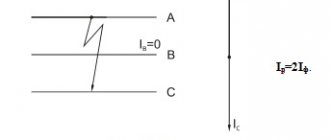
- Defensive protection. This is another type of protection that is used to turn off equipment when an interturn short circuit or overlap occurs on a bus bridge. To do this, the balance of currents is reduced, which is taken from CTs of 110 and 10 kV. This is the trigger zone, so TSN also falls here.
Another protective relay is considered to be backup protection like PUMA or similar. Serves as the last “stronghold”.
Home page
| Name and dimension of the indicator | TMN-6300/110 | |
| Climatic modification and placement category | U1 | |
| Rated power, kVA | HV winding | 6 300 |
| LV winding | 6 300 | |
| Rated frequency, Hz | 50 | |
| Winding connection diagram and group | Y-o/ Δ -11 | |
| Rated voltage value, kV | VN | 110 |
| NN | 11 (±9×1,78%) | |
| Short circuit voltage, Uk, % | 10,5 | |
| No-load current, no more, % | 1,0 | |
| No-load current losses, kW | ≤10 | |
| Short circuit loss, kW | ≤44 | |
| Range and number of on-load tap-changer control stages | in neutral VN±9x1.78% | |
| On-load tap-changer protective relay | URF-25/10 (RS-2001) | |
| Test voltage of full lightning impulses, kV | line clamp | not less than 480 |
| neutral clamp | not less than 200 | |
| One-minute test voltage, kV | line clamp | not less than 200 |
| neutral clamp | not less than 100 | |
| Transformer cooling: M-oil with air blast and natural oil circulation | ||
| Moving the transformer | transverse-longitudinal | |
| Track width, mm | longitudinal movement | 1524 |
| lateral movement | 2000 | |
| Roller shape | with flange | |
| Supply voltage of the cooling system and on-load tap-changer, V | control circuits | ~ 220 |
| signaling circuits | = 220 | |
| engines | ~ 380 | |
| Built-in current transformers | transformation ratio | 300-200-150-100/5 |
| core No. 1 | class 5P/40VA/20 | |
| core No. 2 | class 5P/40VA/20 | |
| Transformer gas relay | for 4 contacts | |
| Gas relay on-load tap-changer | for 2 contacts | |
| Ambient air temperature, оС | -40…+40 | |
| External insulation | category A | |
| Weight, kg | active part | 9130 |
| oils | 9515 | |
| transport | 21480 | |
| full | 24650 | |
| Dispatch (with/without oil) | With butter | |
| Service life, years | 25 | |
| Overall dimensions: (LxBxH), mm | 5090x2685x5110 | |
www.krastehenergo.ru
Output for repair
The power transformer TRDN 110/35/10 kV is taken out for repair using operational switching forms. The latter are developed based on the primary connection diagram and the switching devices used. To carry out this task you will need:
- To remove it for repair, the load on the 10 and 35 kilovolt side is removed.
- Disconnection of the 110 kV side is carried out through a short circuit-isolator connection or using SF6 circuit breakers.
- The output of overlays and automation is carried out on the basis of a relay circuit. The TSN load is transferred. According to the mode, ZON-110 kV is turned on.
Grounding is carried out on each side from which voltage can be supplied. The grounding blades on the switch or on the transformer disconnector RLNDz-110 are turned on, the circuit breaker on the 35 kV MV is turned on, and portable grounding is installed on the 10 kV bus bridge.