Device selection
Voltage stabilizer 12 volts
When choosing a stabilizer, take into account the following characteristics:
- Dimensions. The selected stabilizer must be compactly placed in its planned installation location with normal access.
- View. Of the commercially available devices, the most reliable, compact and inexpensive are stabilizers based on small microcircuits.
- Possibility of self-repair. Since even the most reliable devices fail, it is necessary to give preference to repairable stabilizers, radio components for which are commercially available in sufficient quantities and at an affordable price.
- Reliability. The selected stabilizer must provide a constant voltage value without significant deviations from the range declared by their manufacturer.
- Price. For the electrical system of a car, it is enough to purchase a device costing up to 200 rubles.
Key type voltage stabilizers
This kind of 12V switching voltage regulator has an efficiency of 60%. The main problem is that it is not able to cope with electromagnetic interference. In this case, devices with a power of more than 10 W are at risk. Modern models of these stabilizers can boast a maximum voltage of 12 V. The load on the resistors is significantly reduced. Thus, on the way to the capacitor, the voltage can be completely converted. The current frequency is directly generated at the output. The wear on the capacitor in this case is minimal.
Another problem is related to the use of simple capacitors. In fact, they performed quite poorly. The whole problem lies precisely in the high-frequency emissions that occur in the network. To solve this problem, manufacturers began to install electrolytic-type capacitors on the pulse voltage stabilizer (12 volts). As a result, the quality of work was improved by increasing the capacity of the device.
Adjustable Voltage Stabilizer for Charger
A charger for car batteries is an irreplaceable thing that every car enthusiast should have, no matter how good the battery is, since it can fail at the most inconvenient moment.
We have repeatedly reviewed the designs of numerous chargers on the pages of the site. The charger is, in theory, nothing more than a power supply with current and voltage stabilization. It works simply - we know that the voltage of a charged car battery is about 14-14.4 Volts, you need to set exactly this voltage on the charger, then set the desired charging current, in the case of acid starter batteries this is a tenth of the battery capacity, for example - a 60 A battery /h, we charge it with a current of 6 Amps.
Adjustable Voltage Stabilizer for Charger
As a result, as the battery charges, the current will drop and eventually reach zero - as soon as the battery is charged. This system is used in all chargers; the charging process does not need to be constantly monitored, since all output parameters of the charger are stable and do not depend on changes in mains voltage.
Based on this, it becomes clear that to build a charger you need to have three nodes.
1) Step-down transformer or switching power supply plus rectifier2) Current stabilizer3) Voltage stabilizer
With the help of the latter, the voltage threshold is set to which the battery will be charged, and today we will talk specifically about the voltage stabilizer.
The system is incredibly simple, only 2 active components, minimal costs, and assembly will take no more than 10 minutes if all components are available.
What we have . a field-effect transistor as a power element, an adjustable zener diode that sets the stabilization voltage, this voltage can be set manually using a variable (or better yet, a tuning, multi-turn) 3.3 kOhm resistor. A voltage of up to 50 Volts can be supplied to the input of the stabilizer, and at the output we already obtain a stable voltage of the required rating.
The minimum possible voltage is 3 Volts (depending on the field-effect transistor), the fact is that in order for the field-effect transistor to open at its gate, you need to have a voltage above 3 volts (in some cases more) except for field-effect transistors that are designed to operate in circuits with a logical control level.
Easy about simple things. Current strength, voltage and their stabilization
Voltage determines how quickly electrons move through a conductor. Many passionate fans of hard computer overclocking increase the voltage of the central processor core, making it start to function faster.
Current strength is the density of electron movement within an electrical conductor. This parameter is extremely important for radioelements operating on the principle of thermionic secondary emission, in particular, light sources. If the cross-sectional area of the conductor is not able to pass the flow of electrons, excess current begins to be released in the form of heat, causing significant overheating of the part.
Plasma arc from high voltage
To better understand the process, let’s analyze the plasma arc (electric ignition of gas stoves and boilers works on its basis). At very high voltages, the speed of free electrons is so high that they can easily “fly” the distance between the electrodes, forming a plasma bridge.
And this is an electric heater. When electrons pass through it, they transfer their energy to the heating element. The higher the current, the denser the flow of electrons, the more the thermoelement heats up.
Why is current and voltage stabilization necessary?
Any radio-electronic component, be it a light bulb or a computer's central processor, requires for optimal operation a clearly limited number of electrons that flow through the conductors.
Since our article is about a stabilizer for LEDs, we’ll talk about them.
With all their advantages, LEDs have one drawback - high sensitivity to power parameters. Even moderate excess of force and voltage can lead to burnout of the light-emitting material and failure of the diode.
Nowadays it is very fashionable to remodel a car's lighting system for LED lighting. Their color temperature is much closer to natural light than that of xenon and incandescent lamps, which makes the driver much less tired on long trips.
However, this solution requires a special technical approach. The rated supply current of a car LED diode is 0.1-0.15 mA, and the starting battery current is hundreds of amperes. This is enough to burn out a lot of expensive lighting elements. To avoid this, use a 12 volt stabilizer for LEDs in cars.
The amperage in a vehicle network is constantly changing. For example, a car air conditioner “eats” up to 30 amperes; when it is turned off, the electrons “allocated” to its operation will no longer return back to the generator and battery, but will be redistributed among other electrical appliances. If an additional 300 mA does not play a role in an incandescent lamp rated at 1-3 A, then several such surges can be fatal for a diode with a supply current of 150 mA.
To guarantee long-term operation of automotive LEDs, a current stabilizer based on lm317 is used for high-power LEDs.
Assembling a current stabilizer from two transistors
In this circuit, the sensor functions are performed by resistor R2. Its value when connecting LEDs is selected using the formula:
0.6/In (load current).
An increase in In opens VT2, which, in turn, locks the transition of transistor VT1.
Experts consider a significant voltage drop across the main transistor to be a disadvantage of the circuit. There are no problems when connecting several LEDs. However, as the load increases, it is necessary to place VT1 on a large radiator to ensure effective ventilation of the working volume. Such solutions are used to create powerful chargers.
Voltage converters based on multivibrators
LED power supplies based on multivibrators are shown in Figures 6 and 7. The first circuit is based on an asymmetric multivibrator, which, like the devices (Figures 1 - 5), produces short pulses with a long interpulse pause.
Rice. 6. Low-voltage voltage converter based on an asymmetric multivibrator.
Energy storage - electrolytic capacitor SZ is periodically charged from the power source and discharged to the LED, summing its voltage with the supply voltage.
Unlike the previous circuit, the generator (Fig. 7) ensures that the LED glows continuously. The device is based on a symmetrical multivibrator and operates at higher frequencies.
Rice. 7. Converter for powering the LED from a low-voltage source of 0.8 - 1.6V.
In this regard, the capacitance of the capacitors in this circuit is 3...4 orders of magnitude lower. At the same time, the brightness of the glow is noticeably reduced, and the average current consumed by the generator at a power source voltage of 1.5 6 does not exceed 3 mA.
Design and operating principle
The stabilizer ensures constant current when it deviates. The stabilizer ensures constant operating current of LED diodes when it deviates from the norm. It prevents overheating and burnout of LEDs, maintains constant flow during voltage surges or battery discharge.
The simplest device consists of a transformer, a rectifier bridge connected to resistors and capacitors. The action of the stabilizer is based on the following principles:
- supplying current to the transformer and changing its limiting frequency to the mains frequency - 50 Hz;
- voltage adjustment to increase and decrease with subsequent frequency equalization to 30 Hz.
The conversion process also uses high-voltage rectifiers. They determine the polarity. Stabilization of the electric current is carried out using capacitors. Resistors are used to reduce interference.
Converter circuits of the inductive or capacitive three-point type
Another type of converter is shown in Figures 23 - 29. Their feature is the use of inductive energy storage devices and circuits made of the “inductive” or “capacitive three-point” type with a barrier mode for turning on the transistor. The generator (Fig. 23) is operational in the voltage range from 0.66 to 1.55 V. To optimize the operating mode, it is necessary to select the value of resistor R1. As an inductor, as in many previous circuits. an IF filter circuit coil with an inductance of 260 μH was used.
Rice. 23. Voltage converter for LED on one transistor KT315.
Thus, with the number of turns of the primary winding n(1) equal to 50...60 and the number of turns of the secondary winding l(II) - 12, the device is operational in the supply voltage range of 260...440 mV (ratio of the number of turns 50 to 12), and with the ratio of the number of turns 60 to 12 - 260...415 mV.
When using a ferrite core of a different type or size, this ratio may be disrupted and be different. It is useful to carry out such a study yourself, and present the results in the form of a graph for clarity.
It seems very interesting to use a tunnel diode in the generators under consideration (similar to the one shown in Fig. 20), connected instead of the emitter-base transition of transistor VT1.
The generator (Fig. 24) is slightly different from the previous one (Fig. 23). Its interesting feature is that the brightness of the LED changes with increasing supply voltage (Fig. 25).
Rice. 24. Voltage converter with variable LED brightness.
Rice. 25. Graph of the dependence of the brightness of the LED on the voltage supplying the generator (for Figure 24).
Moreover, the maximum brightness is achieved at 940 mV. The converter shown in Figure 26 can be classified as a three-point generator, with the LED acting as one of the capacitors.
The transformer of the device is made on a ferrite ring (1000HM) K10x6x2.5, and its windings contain approximately 15...20 turns of PELSHO 0.18 wire.
Rice. 26. Low-voltage voltage converter with a three-point generator.
The converter (Fig. 27) differs from the previous one in the LED connection point. The dependence of the brightness of the LED on the supply voltage is shown in Figure 28: as the supply voltage increases, the brightness first increases, then sharply decreases, and then increases again.
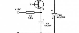
Rice. 27. A simple voltage converter for low-voltage power supply of the AL307 LED.
Rice. 28. Dependence of LED brightness on supply voltage.
The simplest circuit for converters of this type is the circuit shown in Figure 29. Setting the operating point is achieved by selecting resistor R1.
The LED, as in a number of previous circuits, simultaneously plays the role of a capacitor. As an experiment, it is recommended to connect a capacitor in parallel with the LED and select its capacitance.
Rice. 29. A very simple circuit of a low-voltage voltage converter using one transistor.
ADJUSTABLE POWER SUPPLY WITH OVERLOAD ALARM
An audible alarm allows the user to quickly respond to an emergency if an overload of the power source occurs during experiments with various electronic equipment. The diagram of a power supply with an audible alarm for excess current consumption is shown in the figure.
The diode rectifier VD1-VD4 is powered by a transformer, the secondary casing of which is designed for a voltage of 18 V with a load current of at least 1 A. The adjustable voltage stabilizer is made using transistors VT2 - VT5 according to a well-known circuit. The variable resistor R3 at the output of the stabilizer can set the voltage from 0 to +15 V.
Current stabilizers | PRO diode
10/25/2013 | Category: Electronics
There are times when you need to pass a stable current through LEDs, limit the charging current of batteries, or test a power source, but you don’t have a rheostat at hand. In this, and not only, case, special circuit solutions that limit, regulate and stabilize the current will help. The following describes in detail the circuits of stabilizers and current regulators.
Current sources, unlike voltage sources, stabilize the output current by varying the output voltage so that the current through the load always remains the same. Thus, a current source is different from a voltage source, just as water is different from land. Typical applications of current sources are powering LEDs, charging batteries, etc.
Attention! Do not confuse a current stabilizer with a voltage stabilizer! This could end badly =)
Simple current stabilizer on Krenka
For this current stabilizer, it is enough to use KR142EN12 or LM317. These are adjustable voltage stabilizers capable of operating with currents up to 1.5A, input voltages up to 40V and dissipate power up to 10W (subject to thermal conditions). The circuit and application are shown in the pictures below
Current stabilizer on KR142EN12 (LM317)
Current stabilizer on KREN as a charger
The internal consumption of these microcircuits is relatively small - about 8 mA, and this consumption practically does not change when the current flowing through the bank changes or the input voltage changes.
As we can see, in the above diagrams, the LM317 stabilizer works as a voltage stabilizer, maintaining a constant voltage across resistor R3, which can be adjusted within certain limits by adjusting resistor R2. In this case, R3 is called a current-setting resistor.
Since the resistance R3 is constant, the current through it will be stable. The current at the bank input will be approximately 8mA more.
Thus, we got a current stabilizer as simple as a broom, which can be used as an electronic load, a current source for charging batteries, etc.
Integrated stabilizers react quite quickly to changes in input voltage. The disadvantage of such a current regulator is the very high resistance of the current-setting resistor R3 and, as a consequence, the need to use more powerful and more expensive resistors.
A simple current stabilizer on two transistors
Simple current stabilizers based on two transistors have become quite widespread. The main disadvantage of this circuit is that the current stability in the load is not very good when the supply voltage changes. However, for many applications such characteristics are also suitable.
The following shows a circuit of a current stabilizer on a transistor. In this circuit, the current-setting resistor is R2. As the current through VT2 increases, the voltage on the current-setting resistor R2 will increase, which, at a value of approximately 0.5...0.6 V, begins to open transistor VT1. Transistor VT1, opening, begins to close transistor VT2 and the current through VT2 decreases.
Current stabilizer on transistors
Charging batteries
Instead of bipolar transistor VT2, you can use a MOSFET - field-effect transistor.
Zener diode VD1 is selected for a voltage of 8...15V and is necessary in cases where the voltage of the power source is high enough and can break through the gate of the field-effect transistor. For high-power MOSFETs this voltage is about 20V. The following is a current stabilizer circuit using MOSFET.
Current stabilizer on a field-effect transistor
It must be taken into account that MOSFETs open when the gate voltage is at least 2V, and the voltage required for normal operation of the current stabilizer circuit increases accordingly. When charging batteries and some other tasks, it will be quite enough to connect transistor VT1 with resistor R1 directly to the power source as shown in the figure:
Current stabilizer on a field-effect transistor
In current stabilizer circuits using transistors, the required value of the current-setting resistor for a given current value is approximately two times less than in circuits with a stabilizer based on KR142EN12 or LM317. This allows you to use a current-setting resistor of lower power.
Current stabilizer on an operational amplifier (op-amp)
If you need to assemble a current stabilizer that is adjustable over a wide range or a current stabilizer with a current-setting resistor an order of magnitude or even two lower than in the circuits shown earlier, you can use a circuit with an error amplifier on an op-amp (operational amplifier). The circuit of such a current stabilizer is shown in Fig:
Operational amplifier current stabilizer
In this circuit, the current-setting resistor is R7. Op-amp DA2.2 amplifies the voltage of the current-setting resistor R7 - this is the amplified error voltage. Op-amp DA2.1 compares the reference voltage and the error voltage and regulates the state of the field-effect transistor VT1.
Please note that the circuit requires separate power supplied to the XP2 connector. The supply voltage must be sufficient to operate the circuit components and not exceed the gate breakdown voltage of MOSFET VT1.
As a reference voltage generator in the circuit in Fig. 7 uses the DA1 REF198 microcircuit with an output voltage of 4.096V. This is a fairly expensive microcircuit, so it can be replaced with a regular crank, and if the supply voltage of the circuit (+U) is stable, then you can do without a voltage stabilizer in this circuit. In this case, the variable resistor R is connected not to REF, but to +U. In the case of electronic control of the circuit, pin 3 of DA2.1 can be connected directly to the DAC output.
To configure the circuit, you need to set the slider of the variable resistor R1 to the top position in the circuit, and use the trimming resistor R3 to set the required current value - this value will be the maximum. Now resistor R1 can be used to regulate the current through VT1 from 0 to the maximum current set when setting. Elements R2, C2, R4 are necessary to prevent the circuit from energizing. Due to these elements, the timing characteristics are not ideal, as can be seen in the oscillogram
Oscillogram of a current stabilizer on an op-amp
On the oscillogram, beam 1 (yellow) shows the voltage of the loaded IP (power supply), beam 2 (blue) shows the voltage on the current-setting resistor R7. As you can see, for 80 μs a current flows through the circuit several times greater than the set one.
Circuits of stabilizers and current regulators
Everyone knows that LED light bulbs require twelve volts of power. In a car network, this value can reach up to 15 V. LED elements are very sensitive, such surges are reflected negatively on them. LED lamps may burn out or produce poor quality light (flash, lose brightness, etc.).
To make the LEDs last longer, drivers (resistors) are included in the car's electrical network. When there is instability in the network, devices are installed that maintain a constant value. There are several simple microcircuits that you can use to make a voltage stabilizer with your own hands. All components included in the chain can be purchased at specialized stores. Having basic knowledge of electrical engineering, making devices will not be difficult.
On Krenka
In order to construct a simple 12 volt voltage stabilizer with your own hands, you will need a microcircuit with a consumption of 12 V. In this case, an adjustable 12 V voltage stabilizer LM317 is suitable. It can operate in an electrical network where the input parameter is up to 40 V. In order for the device to operate stably, it is necessary to provide cooling.
Chip rolls
The current regulator on the LM317 requires a small current of up to 8 mA to operate, and this value usually remains the same even when large current flows through the LM317 bank or when the input value changes. This is implemented using the R3 component.
You can use the R2 element, but the limits will be small. If the resistance of LM317 remains constant, the current flowing through the device will also be stable (author of the video - Created in Garage).
The input value for the LM317 bank can be up to 8 mA and higher. Using this microcircuit, you can come up with a current stabilizer for DRLs. This device can act as a load in the on-board network or a source of electricity when recharging the battery. Making a simple voltage regulator LM317 is not difficult.
On two transistors
Today, stabilizing devices for the on-board network of a 12 V car, developed using two transistors, are popular. This microcircuit is used as a voltage stabilizer for DRLs.
Resistor R2 is a current-distributing element. As the current in the network increases, the voltage increases. If it reaches a value from 0.5 to 0.6 V, element VT1 opens. Opening component VT1 closes element VT2. As a result, the current passing through VT2 begins to decrease. You can use a Mosfet field-effect transistor together with VT2.
Element VD1 is included in the circuit when the values are in the range from 8 to 15 V and are so large that the transistor may fail. With a powerful transistor, readings in the on-board network of about 20 V are acceptable. Do not forget that the Mosfet transistor will open if the readings at the gate are 2 V.
On an operational amplifier (op-amp)
A voltage stabilizer for LEDs based on an op-amp is assembled if it is necessary to create a device that will operate in an extended range. In the case under consideration, the element that will set the rectified current is R7. Using the DA2.2 operational amplifier, you can increase the voltage level in the current-setting component. The task of the DA 2.1 component is to control the reference voltage.
When creating the circuit, you should take into account that it is designed for 3A, so more current is required, which must be supplied to the XP2 connector. In addition, the functionality of all components of this device should be ensured.
The made stabilizing device for a car must have a generator, the role of which is performed by REF198. To properly configure the device, the slider of resistor R1 must be set to the upper position, and resistor R3 must be used to set the required value of the rectified current 3A. To suppress possible excitations, elements R,2 R4 and C2 are used.
On a pulse stabilizer chip
If a rectifier for a car must provide high efficiency in the network, it is advisable to use switching components, creating a switching voltage stabilizer. The MAX771 circuit is popular.
Switching rectifier circuit
The switching current stabilizer is characterized by an output power of 15 W. Elements R1 and R2 divide the output of the circuit. If the divided voltage exceeds the reference voltage, the rectifier automatically reduces the output value. Otherwise, the device will increase the output parameter.
Assembly of this device is advisable if the level exceeds 16 V. R3 components are current. To eliminate the high load drop across this resistor, an op-amp should be included in the circuit.
Linear type stabilizing devices
Using a stabilizer, the current passing through the LED is set to a specified value, independent of the voltage applied to the circuit. If the voltage exceeds the threshold level, the current will still remain the same and will not change. In the future, when the total voltage increases, its increase will occur only at the current stabilizer, and at the LED it will remain unchanged.
Thus, with unchanged LED parameters, the current stabilizer can be called a power stabilizer. The distribution of active power generated by the device in the form of heat occurs between the stabilizer and the LED in proportion to the voltage on each of them. This type of stabilizer is called linear.
Scheme number 1
There was a stabilized switching power supply that gave an output voltage of 17 volts and a current of 500 milliamps. A periodic change in voltage was required in the range of 11 - 13 volts. And the well-known voltage regulator circuit on one transistor coped with this perfectly. I added only an indication LED and a limiting resistor to it. By the way, the LED here is not only a “firefly” signaling the presence of output voltage. With the correct value of the limiting resistor, even a small change in the output voltage is reflected in the brightness of the LED, which provides additional information about its increase or decrease. The output voltage could be changed from 1.3 to 16 volts.
KT829, a powerful low-frequency silicon compound transistor, was installed on a powerful metal radiator and it seemed that, if necessary, it could easily withstand a heavy load, but a short circuit occurred in the consumer circuit and it burned out. The transistor has a high gain and is used in low-frequency amplifiers - you can really see its place there and not in voltage regulators.
On the left are removed electronic components, on the right are prepared for replacement. The difference in quantity is two items, but in terms of the quality of the circuits, the former and the one that was decided to be collected, it is incomparable. This begs the question: “Is it worth assembling a scheme with limited capabilities when there is a more advanced option “for the same money”, in the literal and figurative sense of this saying?”
Stabilizer for LEDs
The easiest way to make a current stabilizer for LEDs with your own hands is using LM317; you just need to calculate the resistor for the LED using an online calculator. Food can be used at hand, for example:
- laptop power supply 19V;
- from the printer at 24V and 32V;
- from consumer electronics at 12 volts, 9V.
The advantages of such a converter are low price, easy to buy, minimum parts, high reliability. If the current stabilizer circuit is more complex, then assembling it with your own hands becomes irrational. If you are not a radio amateur, then a pulse current stabilizer is easier and faster to buy. In the future, it can be modified to the required parameters. You can find out more in the “Ready-made modules” section.
LM317
The use of LM317 (roll) does not even require any skills or knowledge of electronics. The number of external elements in the circuits is minimal, so this is an affordable option for anyone. Its price is very low, its capabilities and applications have been tested and verified many times. Only it requires good cooling, this is its main drawback. The only thing you should be wary of is low-quality Chinese LM317 microcircuits, which have worse parameters.
Due to the absence of excess noise at the output, linear stabilization microcircuits were used to power high-quality Hi-Fi and Hi-End DACs. For DACs, cleanliness of power plays a huge role, so some use batteries for this.
The maximum power for the LM317 is 1.5 Amps. To increase the number of amperes, you can add a field-effect transistor or a regular one to the circuit. At the output it will be possible to get up to 10A, set by low-resistance resistance. In this diagram, the main load is taken by the KT825 transistor.
Another way is to install an analogue with higher technical characteristics on a larger cooling system.
Voltage converters of inductive and inductive-capacitive type
Figures 14 - 18 show converters for powering LEDs of inductive and inductive-capacitive type, made on the basis of generators using analogues of an injection field-effect transistor as an active element [Rk 5/00-23].
Rice. 14. Scheme of a low-voltage voltage converter 1-6V to 2V of inductive-capacitive type.
The converter shown in Figure 14 is an inductive-capacitive type device. The pulse generator is made on an analogue of an injection field-effect transistor (transistors VT1 and VT2).
The elements that determine the operating frequency of generation in the audio frequency range are the telephone capsule BF1 (type TK-67), capacitor C1 and resistor R1. Short pulses generated by the generator arrive at the base of transistor VT3, opening it.
At the same time, the charge/discharge of the capacitive energy storage unit (capacitor C2) occurs. When a pulse arrives, the positively charged plate of capacitor C2 is connected to the common bus through transistor VT2, which is open for the duration of the pulse. Diode VD1 closes, transistor VT3 opens.
Thus, a power source and a charged capacitor C2 are connected in series to the load circuit (LED HL1), resulting in a bright flash of the LED.
Transistor VT3 allows you to expand the range of operating voltages of the converter. The device is operational at voltages from 1.0 to 6.0 V. Let us recall that the lower limit corresponds to a barely noticeable glow of the LED, and the upper limit corresponds to the device’s current consumption of 20 mA.
In the region of low voltages (up to 1.45 V), sound generation is not audible, although as the supply voltage subsequently increases, the device begins to produce sound signals, the frequency of which decreases quite quickly.
The transition to higher operating frequencies (Fig. 15) through the use of a high-frequency coil makes it possible to reduce the capacitance of the capacitor that “pumps” energy (capacitor C1).
Rice. 15. Schematic diagram of a low-voltage voltage converter with an HF generator.
A field-effect transistor VT3 (KP103G) is used as a key element that connects the LED to the “positive” power bus for the pulse repetition period. As a result, the operating voltage range of this converter has been expanded to 0.7 ... 10 V.
Noticeably simplified devices, but operating within a limited range of supply voltages, are shown in Figures 16 and 17. They provide LED illumination in the range of 0.7...1.5 V (at R1=680 Ohm) and 0.69...1.2 V (at R1=0 Ohm), as well as from 0.68 to 0.82 V (Fig. 17).
Rice. 16. Schematic diagram of a simplified low-voltage voltage converter with an HF generator.
Rice. 17. Simplified low-voltage voltage converter with an RF generator and a telephone capsule as a coil.
The simplest generator is based on an analogue of an injection field-effect transistor (Fig. 18), where the LED simultaneously acts as a capacitor and is the load of the generator. The device operates in a rather narrow range of supply voltages, but the brightness of the LED is quite high, since the converter (Fig. 18) is purely inductive and has high efficiency.
Rice. 18. Low-voltage voltage converter with a generator based on an analogue of an injection field-effect transistor.
The next type of converter is quite well known and is more traditional. These are transformer and autotransformer type converters.
In Fig. Figure 19 shows a transformer-type generator for powering LEDs with low voltage voltage. The generator contains only three elements, one of which is a light-emitting diode.
Without an LED, the device is a simple blocking generator, and a fairly high voltage can be obtained at the output of the transformer. If you use an LED as a generator load, it begins to glow brightly even at a low supply voltage (0.6...0.75 V).
Rice. 19. Circuit of a transformer type converter for powering LEDs with low voltage voltage.
In this circuit (Fig. 19), the transformer windings have 20 turns of PEV 0.23 wire. A ferrite ring M1000 (1000NM) K 10x6x2.5 was used as the transformer core. In the absence of generation, the conclusions of one of the transformer windings are as follows! swap. The converter shown in Figure 20 has the lowest supply voltage of all the devices considered. A significant reduction in the lower limit of the operating voltage was achieved by optimizing the choice of the number (ratio) of winding turns and the method of their inclusion. When using high-frequency germanium transistors such as 1T311, 1T313 (GT311, GT313), such converters begin to operate at a supply voltage above 125 mV.
Rice. 20. Low voltage voltage converter from 0.25V - 0.6V to 2V.
Rice. 21. Experimentally measured characteristics of the generator.
As in the previous circuit, a ferrite ring M1000 (1000NM) K10x6x2.5 was used as the transformer core. The primary winding is made of PEV 0.23 mm wire, the secondary winding is made of PEV 0.33. A fairly bright glow of the LED is observed already at a voltage of 0.3 V.
Figure 21 shows the experimentally measured characteristics of the generator (Fig. 20) when varying the number of turns of the windings. From the analysis of the obtained dependencies it follows that there is an area of optimal ratio between the number of turns of the primary and secondary windings, and with an increase in the number of turns of the primary winding, the minimum operating voltage of the converter gradually decreases, and at the same time the range of operating voltages of the converter narrows.
To solve the inverse problem - expanding the operating voltage range of the converter - an RC circuit can be connected in series with it (Fig. 22).
Rice. 22. Circuit of a low-voltage voltage converter using an RC circuit.
Are you here
Home › Design engineer › 3. Electrical equipment, electrical installations › 3. Section 3.
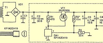
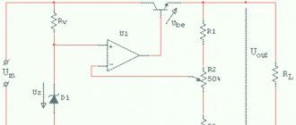
To obtain a more constant voltage across the load when the current consumed changes, a stabilizer is connected to the output of the rectifier, which can be made according to the circuit shown in Fig. 1. This device uses zener diode V5
and control transistor
V6
.
The calculation will allow you to select all elements of the stabilizer based on the specified output voltage Un
and maximum load current
In
. However, both of these parameters should not exceed the parameters of the already calculated rectifier. And if this condition is violated, then the stabilizer is first calculated, and then the rectifier and power transformer. The stabilizer is calculated in the following order.
(Uvyp) required for the stabilizer to operate.
at a given output
(Un)
:
Uvyp = Un + 3
,
Here, number 3, which characterizes the minimum voltage between the collector and emitter of the transistor, is taken based on the use of both silicon and germanium transistors. If the stabilizer is connected to a ready-made or already calculated rectifier, in further calculations it is necessary to use the real value of the rectified voltage Uvyp
.
2. Calculate the maximum power dissipated by the transistor:
Pmax = 1.3 (Uvyp - Un) In
,
3. Select a control transistor. Its maximum permissible power dissipation must be greater than the Pmax
, the maximum permissible voltage between the emitter and the collector is greater than
Uvyp
, and the maximum permissible collector current is greater than
In
.
4. Determine the maximum base current of the regulating transistor:
Ib.max = In / h21E min
,
where: h21Emin is the minimum current transfer coefficient of the selected (according to the reference book) transistor.
.
5. Select a suitable zener diode. Its stabilization voltage must be equal to the output voltage of the stabilizer, and the value of the maximum stabilization current must exceed the maximum base current Ib max
.
6. Calculate the resistance of the resistor R1
:
R1 = (Uvyp - Ust) / (Ib max + Ist min)
,
Here R1 is the resistance of resistor R1, Ohm; Ust — zener diode stabilization voltage, V; Ib.max - calculated value of the maximum base current of the transistor, mA; Ist.min is the minimum stabilization current for a given zener diode, indicated in the reference book (usually 3...5 mA).
.
7. Determine the power dissipation of resistor R1
:
PR1 = (Uvyp - Ust)2 / R1
,
It may happen that a low-power zener diode is not suitable for the maximum stabilization current and you will have to choose a zener diode of significantly higher power - this happens with high consumption currents and using a transistor with a low h21E
.
In this case, it is advisable to introduce an additional low-power transistor V7
(Fig. 2), which will reduce the maximum load current for the zener diode (and therefore the stabilization current) by approximately
h21E
times and, accordingly, use a low-power zener diode.
The calculations presented here do not correct for changes in mains voltage, and also omit some other clarifications that complicate the calculations. It is easier to test the assembled stabilizer in action by changing its input voltage (or mains voltage) by ± 10% and more accurately select resistor R1 based on the greatest stability of the output voltage at maximum load current.
Nuances of calculating a current stabilizer
The stabilizer is calculated based on the stabilization voltage U and current (average) I. For example, the voltage of the input divider is 25 V, the output needs to be 9 V. Calculations include:
- Selection according to the zener diode reference book. Focus on stabilization voltage: D814V.
- Finding the average current I using the table. It is equal to 5 mA.
- Calculation of the supply voltage as the difference between the stable voltage of the input and output: UR1 = Uinx - Uout, or 25-9 = 16 V.
- Dividing the resulting value according to Ohm's law by the stabilization current according to the formula R1 = UR1 / Ist, or 16/0.005 = 3200 Ohm, or 3.2 kOhm. The element rating will be 3.3 kOhm.
- Calculation of maximum power using the formula PR1 = UR1 * Ist, or 16x0.005 = 0.08.
The zener diode current and the output current pass through the resistor, so its power should be 2 times greater (0.16 kW). Based on the table, this rating corresponds to 0.25 kW.
Self-assembly of a stabilizer for LED devices is only possible if you know the circuit. Beginners are recommended to use simple algorithms. You can calculate an element’s power based on formulas from a school physics course.
My experience
My friend has a VAZ PRIORA, and he is a fan of putting LED lamps in the dimensions, headlights, etc. They really didn’t walk for a long time without such stabilizing elements (a couple of months, that’s all). Now one set of cheap options has been running for three years, and all thanks to stabilization!
There are also disadvantages: such elements are placed in the break of the wire that goes to the source; “IN” and “OUT” are even indicated there where the wire should be connected and where to output it. The cost for 5 pieces is approximately 160 rubles, that is, each one is about 30. A friend set it to 11.8V, connected the wires to the boards and filled them with a glue gun, now they are not afraid of moisture.
Personally, I myself bought such boards and experimented with them, I have a power supply that produces from 15 to 24V. From it I powered two wires and connected them to the module, and from there to the LED, I set it to about 11.9. And you know, no matter how I switched the voltage in the power supply, behind the board it remained stable at 11.9V without any jumps (the whole experiment will be on video).
So the conclusion is that you can buy stabilizers (about 30 rubles apiece), the light bulbs themselves (about 50 rubles apiece) and in TOTAL you get an option for 80 - 100 rubles that will work for a very long time (3 years for sure).
Now we are watching the video version
Here is the material, I think it was useful to you, subscribe to the site and the channel will have many more interesting videos. Sincerely yours, AUTOBLOGGER.
Comments
05.01.2020
Maksim
In the truck, the cartridges in the side lights rotted and the 12 V LED matrices fell asleep. And I bought stabilizers on the radio market that look like transistors, three legs, without them it’s impossible since the on-board network is 24 V. Everything has been working for 5 years.
STCSx chips
STCSx is a family of linear current regulator ICs that feature BiCMOS technology and are ideal for applications where the LED load must be powered with up to 2 A of current from a 5, 12, or 24 V DC source. Such applications include illuminated signs and indicators, backlighting displays of portable electronics, automotive lighting, light signaling, etc. The advantages of STCSx include: high accuracy of current stabilization (±1%) and degree of integration, flexibility of application and reliability. The capabilities of the microcircuits are implemented by the structure shown in Fig. 2a. In addition to supplying the LED load with a stabilized current, the value of which is set by an external current-sensing resistor, STCSx supports on/off control functions via the EN input, PWM dimming control via the PWM pin, as well as LED load disconnection detection and signaling on the DISC pin. The range and main operating characteristics of STCSx microcircuits can be found in Table 1. Drivers with the letter “A” at the end of the name are distinguished by their support for the additional function of controlling the duration of the edges of output current pulses from tens of microseconds to tens of milliseconds. The duration is set by an external capacitor through a special SLOPE pin. This function is necessary in cases where there are special requirements for the level of electromagnetic radiation.
Table 1. Main characteristics of STCSx drivers
| Name | IOUT, A | VIN, V | Col. SD | Frame | Additional functions |
| STCS05 | 0,5 | 4,5…40 | ≤9 | SO8 | 1) PWM dimming input |
| STCS05A | 0,5 | 4,5…40 | ≤9 | SO8 | 2) Diagnostics |
| STCS1 | 1,50 | 4,5…40 | ≤9 | DFN3x3-8L/HSOP8 | 3) Enable/disable input EN |
| STCS1A | 1,50 | 4,5…40 | ≤9 | DFN3x3-8L/HSOP8 | |
| STCS2 | 2 | 4,5…40 | ≤9 | PowerSO-10 | |
| STCS2A | 2 | 4,5…40 | ≤9 | PowerSO-10 |
The considered features and advantages acquire particular significance when compared with similar competing products. In particular, the Maxim company in its product range has a linear current stabilizer MAX16800 for a similar purpose for input voltages up to 40 V, but its capabilities are limited by the output current of 0.35 A, input voltage not lower than 6.5 V, and lower stabilization accuracy (±3. 5%) and a higher threshold voltage at the FB input (204 mV). Load disconnection detection and edge time limiting functions are not provided. Another solution is offered by Texas Instruments. TL4242 chip is designed to operate with an input voltage of 4.5 ... 42 V, supports the function of detecting load disconnection, but it is also inferior in stabilization accuracy (±5%), output current (up to 0.5 A) and threshold voltage at the input FB (177 mV vs. 100 mV).
The advantages of a high degree of IC integration are clearly illustrated by the connection diagram shown in Fig. 2b. Here the driver chip is supplemented with several passive components. The current stabilization threshold of 0.5A is set by an external RFB resistor with a nominal value of 0.2 Ohm. The diode installed in the driver power circuit is designed to protect it from supplying a supply voltage of incorrect polarity. Since the driver is made using linear analog circuitry, you need to pay special attention to the choice of driver supply voltage, because the power dissipated by the driver directly depends on it: PD= (VDRAIN- VFB) ILED + (VCC ICC), and therefore the junction temperature: TJ= RthJA PD+ TA, where RthJA is the thermal resistance “junction-environment” of the microcircuit body; TA—ambient temperature.
Rice. 2. Block diagram (a) and connection diagram (b) of the STCS05 microcircuit
The condition for the correct selection of circuit parameters is the selection of a TJ value not higher than the value recommended in the documentation (for example, 110°C for STCS05A ).
To make design easier, ST offers STEVAL-ILL014V1 based on the STCS1 and STCS1ADEMO1 based on the STCS1A (Figure 3).
Rice. 3. Appearance of current source evaluation board based on STCS1A
Current stabilizers on transistors
To stabilize the current through LEDs, you can use well-known solutions:
Figure 1 shows a diagram whose operation is based on the so-called. emitter follower. A transistor connected in this way tends to maintain the voltage at the emitter exactly the same as at the base (the only difference will be the voltage drop across the base-emitter junction). Thus, by fixing the base voltage using a zener diode, we obtain a fixed voltage on R1.
Next, using Ohm's law, we obtain the emitter current: Ie = Ue/R1. The emitter current practically coincides with the collector current, and therefore with the current through the LEDs.
Conventional diodes have a very weak dependence of forward voltage on current, so they can be used instead of hard-to-find low-voltage zener diodes. Here are two variants of circuits for transistors of different conductivities, in which the zener diodes are replaced by two conventional diodes VD1, VD2:
The current through the LEDs is set by selecting resistor R2. Resistor R1 is selected in such a way as to reach the linear section of the I-V characteristic of the diodes (taking into account the base current of the transistor). The supply voltage of the entire circuit must be no less than the total voltage of all LEDs plus about 2-2.5 volts on top for stable operation of the transistor.
Resistance R1 will depend on the coefficient. gain of the transistor hfe and the current-voltage characteristics of the diodes. For S9014 and 1N4148 diodes, 10 kOhm will be enough.
Let's use the described stabilizer to improve one of the LED lamps described in this article. The improved diagram would look like this:
This modification can significantly reduce current ripple and, consequently, the brightness of the LEDs. But the main advantage of the circuit is to normalize the operating mode of the LEDs and protect them from voltage surges during switching on. This leads to a significant extension of the life of the LED lamp.
From the oscillograms it can be seen that by adding a current stabilizer for the LED on a transistor and a zener diode to the circuit, we immediately reduced the ripple amplitude several times:
With the ratings indicated in the diagram, the power dissipated by the transistor is slightly more than 0.5 W, which makes it possible to do without a radiator. If the capacitance of the ballast capacitor is increased to 1.2 μF, then the transistor will drop
23 Volts, and the power will be about 1 W. In this case, you cannot do without a radiator, but the pulsations will drop almost to zero.
Instead of the 2CS4544 transistor indicated in the diagram, you can take 2SC2482 or a similar one with a collector current of more than 100 mA and a permissible voltage Uke of at least 300 V (for example, the old Soviet KT940, KT969 are suitable).
The desired current, as usual, is set by resistor R*. The zener diode is designed for a voltage of 5.1 V and a power of 0.5 W. Common SMD LEDs from Chinese light bulbs are used as LEDs (or better yet, take a ready-made lamp and add the missing components to it).
Now consider the diagram presented in Figure 2. Here it is separately:
The current sensor here is a resistor, the resistance of which is calculated using the formula 0.6/Iload. As the current through the LEDs increases, transistor VT2 begins to open more strongly, which leads to stronger blocking of transistor VT1. The current decreases. This way the output current is stabilized.
Also, instead of a bipolar transistor, you can use a p-channel MOSFET. The circuit below is a powerful lamp using two 10-watt LEDs and a 40-watt IRF9510 in a TO-220 package (see specifications):
Transistor VT2 and LEDs must be placed on a common radiator with an area of at least 900 cm 2 (this is if without forced cooling). The use of thermal paste is mandatory. The radiator fins should be thick and massive in order to remove heat as quickly as possible. Galvanized profiles for drywall, herring cans and pot lids are absolutely not suitable.
If such power is not needed, you can reduce the number of LEDs to one. But in this case you will have to lower the supply voltage by 3-3.5 volts. Otherwise, the power consumption will remain the same, the transistor will heat up twice as hot, and the light will be twice as bad.
Types of current stabilizers
The LED lights up when the current threshold value is reached. For low-power devices this figure is 20 mA, for high-bright devices - from 350 mA. The spread of the threshold voltage explains the presence of different types of stabilizers.
Resistor stabilizers
Stabilizer KREN
For an adjustable stabilizer of current parameters for low-power LEDs, the KREN circuit is used. It provides for the presence of elements KR142EN12 or LM317. The equalization process is carried out at a current of 1.5 A and an input voltage of 40 V. Under normal thermal conditions, the resistors dissipate up to 10 tons of power. Their own power consumption is about 8 mA.
The LM317 node maintains a constant voltage value across the main resistor, regulated by a trimmer. The main, or current-distributing element can stabilize the current passed through it. For this reason, ROLL stabilizers are used to charge batteries.
The 8 mA value does not change even with fluctuations in input current and voltage.
Transistor devices
Transistor voltage stabilizer circuit
The transistor regulator involves the use of one or two elements. Despite the simplicity of the circuit, when voltage fluctuations occur, there is not always a stable load current. As it increases, the resistor voltage on one transistor increases to 0.5-0.6 V. After this, the second transistor starts working. At the moment of its opening, the first element closes, and the strength and magnitude of the current passing through it decreases.
The second transistor must be bipolar.
Two circuits for transistors of different conductivities, in which the zener diodes are replaced by two conventional diodes VD1, VD2
To implement the circuit with replacing zener diodes with diodes, the following are used:
- diodes VD1 and VD2;
- resistor R1;
- resistor R2.
The current flow through the LED element is set by resistor R2. To reach the linear section of the I-V characteristics of diodes tied to the current of the base transistor, resistor R1 is used. In order for the transistor to remain stable, the supply voltage should not be less than the total voltage of the diodes + 2-2.5 V.
To obtain a current of 30 mA, 12 V is supplied in a straight line through 3 series-connected diodes with a voltage of 3.1 V. The resistor resistance should be 20 Ohms with a dissipation power of 18 mW.
The circuit normalizes the operating mode of the elements and reduces current ripples.
Circuit with Soviet transistors. The permissible voltage of the Soviet KT940 or KT969 is up to 300 V, which is suitable if the light source is a powerful SMD element. The current parameters are set by a resistor. The zener diode voltage is 5.1 V, and the power is 0.5 V.
The disadvantage of the circuit is the voltage drop when the current increases. This can be eliminated by replacing the bipolar transistor with a MOSFET with low resistance parameters. The powerful diode is replaced by an IRF7210 12 A element or an IRLML6402 3.7 A element.
Current stabilizers on the field
Voltage stabilizer on a field-effect transistor
The field element is distinguished by a short-circuited source and gate, as well as a built-in channel. When using a field switch (IRLZ 24) with 3 pins, a voltage of 50 V is applied to the input, and the output is 15.7 V.
The ground potential is used to supply voltage. The output current parameters depend on the initial drain current and are not tied to the source.
Linear devices
A stabilizer or constant current divider accepts an unstable voltage. At the output, the linear device equalizes it. It operates on the principle of constantly changing resistance parameters to equalize the output power.
The advantages of operation include a minimum number of parts and no interference. The disadvantage is the low efficiency due to the difference in power supply at the input and output.
Ferroresonant device
A stabilizer for alternating current of an outdated model, the circuit of which is represented by a capacitor and two coils - with an unsaturated and saturated core. A constant type voltage is supplied to the saturated (inductive) core, independent of the current parameters. This facilitates the selection of data for the second coil and the capacitive range of power stabilization.
The device works on the principle of a swing, which is difficult to immediately stop or swing more strongly. The supply of voltage occurs by inertia, so load drops or a break in the power circuit are possible.
Features of the current mirror circuit
Classic current mirror circuit
The current mirror, or reflector, is built on a pair of transistors of a matched type, i.e. with the same parameters. For their production, one LED semiconductor crystal is used.
Scheme of a current mirror according to the Ebers-Moll equation. The principle of operation is that the transistor bases are combined, and the emitters are connected to one power bus. As a result, the parameters of the transient voltage of the base-transistor-emitter coupling are equal.
The advantages of the circuit are an equal range of stability and no voltage drop across the emitter resistor. Parameters are easier to set using current. The disadvantage is the Earley effect - the binding of the output voltage to the collector voltage and its fluctuations.
Wilson current mirror circuit. The current mirror can stabilize a constant value of the output current and is implemented as follows:
- Transistors No. 1 and No. 1 are connected according to the principle of a standard current mirror.
- Transistor No. 3 fixes the collector potential of element No. 1 to twice the diode voltage drop parameter.
- It will be less than the supply voltage, which suppresses the Early effect.
- The collector of transistor No. 1 is activated to establish the circuit mode.
- The output current depends on transistor No. 2.
- Transistor #3 transforms the output current into a variable voltage load.
Transistor No. 3 may not be coordinated with the others.
Compensation voltage stabilizer
Compensating voltage stabilizer
The rectifier operates on the principle of a voltage feedback circuit. Full or partial tension equates to support. As a result, the regulator generates error voltage parameters, eliminating brightness fluctuations for the LEDs. The device consists of the following elements:
- A regulating element or transistor, which together with the load resistance forms a voltage divider. The emitter value of the transistor must exceed the load current by 1.2 times.
- Amplifier – controls the RE, is based on transistor No. 2. The low-power element is consistent with the powerful element according to the composite principle.
- Support voltage source - the circuit uses a parametric type stabilizer. It equalizes the voltage of the zener diode and resistor.
- Additional sources.
- Capacitors - to smooth out ripples and eliminate parasitic excitation.
Compensation voltage stabilizers operate on the principle of increasing the input voltage with a further increase in currents. Closing the first transistor increases the resistance and voltage of the collector-emitter zone. After applying the load, it is leveled to the nominal value.
Devices on chips
Microcircuit 142EN5
For stabilizing devices, the 142EN5 or LM317 microcircuit is used. It allows you to equalize the voltage by receiving a signal from a sensor connected to the load current network through the feedback circuit.
A resistance is used as a sensor, at which the regulator can maintain a constant voltage and load current. The sensor resistance will be less than the load resistance. The circuit is used for chargers, and an LED lamp is designed using it.
Switching stabilizers
The pulse device is characterized by high efficiency and, with minimal input voltage parameters, creates a high consumer voltage. The MAX 771 chip is used for assembly.
One or two converters will regulate the current. A rectifier-type divider equalizes the magnetic field, lowering the permissible voltage frequency. To supply current to the winding, the LED element transmits a signal to transistors. Stabilization at the output is carried out through the secondary winding.
Simple DIY CH
Parametric voltage stabilizer
A 12-volt voltage stabilizer for LEDs, backlights of automotive on-board systems is quickly and conveniently performed using microcircuits: LM317, LD1084, L7812, KREN 8B and similar devices. Several diodes, a resistance and the microcircuit itself are the components of such a circuit.
Stabilizer on LM317
Depending on the manufacturing option of the LM317 case, the arrangement of parts on the board is selected.
LM317 with heatsink mount
Making a stabilizer comes down to the following:
- a resistance with a nominal value of 130 Ohms is soldered to the output (Vout);
- a wire supplying voltage for stabilization is connected to the input contact (Vin);
- the adjustment input (Adj) is connected to the second terminal of the resistor.
When connecting LED lights, strips, etc. as a load. no radiator required. Assembly takes 15-20 minutes with a minimum of parts. Using a simple formula, you can calculate the value of resistance R to obtain a certain value of the permissible load current.
CH circuit on LM317
Circuit on the LD1084 chip
The use of this microassembly will help maintain the 12 V voltage constant for LED illumination devices connected to the vehicle’s on-board network.
Datasheet LD1084
Here, to assemble a homemade CH, the following is included in the circuit binding circuit of the microcircuit:
- two electrolytic capacitors of 10 μF * 25 V;
- resistors: 1 kOhm (2 pcs.), 120 Ohm, 4.7 kOhm (can be constant);
- diode bridge RS407.
The device is assembled as follows:
- the voltage removed from the rectifier diode bridge is supplied to the input of LD1084;
- the emitter of the KT818 transistor is connected to the contact that controls the stabilization mode (Adj), the base of which is connected through two single-column resistors to the power supply circuits for the headlights (low and high);
- the output circuit of the microcircuit is connected to resistors R1 and R2, as well as a capacitor.
By the way. Resistor R2 can be taken not as a variable, but as a tuning one, using it to set the output voltage to 12 V.
SN for on-board network
Stabilizer on diodes and assembly L7812
A similar microcircuit in conjunction with a diode and capacitors can supply LEDs with a stable voltage of 12 V.
The scheme is built according to the principle outlined below:
- The 1N401 Schottky diode passes current from the positive terminal of the battery through itself and supplies it to the input of the microcircuit. In this case, the “+” of the electrolyte (330 μF capacitor) is also connected to the cathode of the diode;
- a load circuit and a “+” capacitor with a capacity of 100 μF are connected to the output of L7812;
- all negative terminals (from the battery and both electrolytic capacitors) are connected to the control input of the microcircuit.
Electrolytic capacitors are selected for a voltage of at least 25 V.
12 V stabilizer circuit on IC L7812
The simplest stabilizer is the KREN board
Schemes using rolls are quite popular. This is the name for ICs whose markings include combinations of the letters KR and EN. These are powerful SNs that allow you to supply a current of up to 1.5 A to the load. They have a stable 12 V output when a voltage of up to 35 V is applied to the input.
The circuit using this microcircuit is assembled like this:
- voltage from the positive terminal of the battery (rechargeable battery) to the bank input is supplied through a 1N4007 diode, it protects the battery circuit from reverse voltages;
- the negative terminal of the battery is connected to the control electrode KREN;
- The output voltage is supplied to the load.
If necessary, the microcircuit is screwed to the radiator.
KR142EN8B, connection diagram
Assembling 12 V voltage stabilizers with your own hands using linear and integrated MV circuits is not difficult. In this case, it is necessary to monitor the heating temperature of the housing of the elements and, when T0C is higher than permissible, install them on heat sinks (radiators).
DIY adjustable power supply
A power supply is a necessary thing for every radio amateur, because to power electronic homemade products you need a regulated power source with a stabilized output voltage from 1.2 to 30 volts and a current of up to 10A, as well as built-in short circuit protection. The circuit shown in this figure is built from the minimum number of available and inexpensive parts.
Scheme of an regulated power supply on an LM317 stabilizer with short-circuit protection
The LM317 IC is an adjustable voltage regulator with built-in short circuit protection. The LM317 voltage stabilizer is designed for a current of no more than 1.5A, so a powerful MJE13009 transistor is added to the circuit, capable of passing through itself a really high current of up to 10A, according to the datasheet, a maximum of 12A. When you rotate the knob of the variable resistor P1 by 5K, the voltage at the output of the power supply changes.
There are also two shunt resistors R1 and R2 with a resistance of 200 Ohms, through which the microcircuit determines the output voltage and compares it with the input voltage. 10K resistor R3 discharges capacitor C1 after the power supply is turned off. The circuit is powered by voltage from 12 to 35 volts. The current strength will depend on the power of the transformer or switching power supply.
I drew this diagram at the request of novice radio amateurs who assemble circuits using wall-mounted installations.
Scheme of an regulated power supply with short-circuit protection on LM317
It is advisable to carry out the assembly on a printed circuit board, so it will be beautiful and neat.
Printed circuit board of the regulated power supply on the LM317 voltage regulator
The printed circuit board is made for imported transistors, so if you need to install a Soviet one, the transistor will have to be unfolded and connected with wires. The MJE13009 transistor can be replaced with the MJE13007 from the Soviet KT805, KT808, KT819 and other npn structure transistors, it all depends on the current you need. It is advisable to reinforce the power paths of the printed circuit board with solder or thin copper wire. The LM317 voltage stabilizer and the transistor must be installed on a radiator with sufficient area for cooling; a good option is, of course, a radiator from a computer processor.
It is advisable to screw a diode bridge there. Don't forget to insulate the LM317 from the heatsink with a plastic washer and a heat conductive gasket, otherwise there will be a big boom. Almost any diode bridge can be installed with a current of at least 10A. Personally, I installed the GBJ2510 at 25A with double the power reserve, it will be twice as cool and reliable.
And now the most interesting part... Testing the power supply for strength.
I connected the voltage regulator to a power source with a voltage of 32 volts and an output current of 10A. Without load, the voltage drop at the output of the regulator is only 3V. Then I connected two series-connected halogen lamps H4 55 W 12V, the lamp filaments were connected together to create a maximum load, the result was 220 W. The voltage dropped by 7V, the nominal voltage of the power supply was 32V. The current consumed by four halogen lamp filaments was 9A.
The radiator began to heat up quickly, after 5 minutes the temperature rose to 65C°. Therefore, when removing heavy loads, I recommend installing a fan. You can connect it according to this diagram. You can not install the diode bridge and capacitor, but connect the L7812CV voltage stabilizer directly to capacitor C1 of the regulated power supply.
Connection diagram of the fan to the power supply
What happens to the power supply if there is a short circuit?
In the event of a short circuit, the voltage at the output of the regulator is reduced to 1 volt, and the current is equal to the current of the power source, in my case 10A. In this state, with good cooling, the unit can remain for a long time; after the short circuit is eliminated, the voltage is automatically restored to the limit set by the variable resistor P1. During the 10-minute short-circuit test, no parts of the power supply were damaged.
Radio components for assembling an adjustable power supply on LM317
- Voltage stabilizer LM317
- Diode bridge GBJ2501, 2502, 2504, 2506, 2508, 2510 and other similar ones designed for a current of at least 10A
- Capacitor C1 4700mf 50V
- Resistors R1, R2 200 Ohm, R3 10K all resistors with a power of 0.25 W
- Variable resistor P1 5K
- Transistor MJE13007, MJE13009, KT805, KT808, KT819 and other npn structures
Friends, I wish you good luck and good mood! See you in new articles!
I recommend watching a video on how to make an adjustable power supply with your own hands
Regulator characteristics
Depending on their type, devices can be manufactured in portable or stationary versions. They can be installed in any position: vertical, ceiling, horizontal.
The main characteristics of the devices include the following parameters:
- Smooth adjustment. Indicates the minimum step with which the potential difference at the output changes. The smoother it is, the more accurately you can set the output voltage value.
- Operating power. It is characterized by the value of current that can pass through the device for a long time without damaging its electronic connections.
- Maximum power. The peak value that a device can withstand for a short time while maintaining its functionality.
- Input voltage range. These are the input signal values with which the device can operate.
- The range of the variable signal at the device output. Indicates the potential difference that the device can provide at the output.
- Type of adjustable signal. Both alternating and direct voltage can be supplied to the input of the device.
- Terms of Use. Indicates conditions under which the controller characteristics do not change.
- Control method. The output signal level can be set by the user manually or without his intervention.
Datasheet for lm317, lm350, lm338
Before moving directly to the circuits, let's consider the features and technical characteristics of the above linear integrated stabilizers (LIS).
All three IMs have a similar architecture and are designed to build on their basis simple current or voltage stabilizer circuits, including those used with LEDs. The differences between the microcircuits lie in the technical parameters, which are presented in the comparison table below.
| LM317 | LM350 | LM338 | |
| Adjustable output voltage range | 1.2…37V | 1.2…33V | 1.2…33V |
| Maximum current load | 1.5A | 3A | 5A |
| Maximum permissible input voltage | 40V | 35V | 35V |
| Indicator of possible stabilization error | ~0,1% | ~0,1% | ~0,1% |
| Maximum power dissipation* | 15-20 W | 20-50 W | 25-50 W |
| Operating temperature range | 0° - 125°С | 0° - 125°С | 0° - 125°С |
| Datasheet | LM317.pdf | LM350.pdf | LM338.pdf |
* – depends on the MI manufacturer.
All three microcircuits have built-in protection against overheating, overload and possible short circuit.
Lm317, the most common IM, has a complete domestic analogue - KR142EN12A.
Integrated stabilizers (IS) are produced in a monolithic package of several variants, the most common being TO-220.
The microcircuit has three outputs:
- ADJUST. Pin for setting (adjusting) the output voltage. In current stabilization mode, it is connected to the positive of the output contact.
- OUTPUT. A pin with low internal resistance to generate output voltage.
- INPUT. Output for supply voltage.
LED strip power supply repair
Many power supplies designed for medium and high power (30 W or more) are built on an integrated driver with a built-in power switch, such as KA5l0365, FSDH065RN, etc. Such solutions are also used in household appliances, for example, in power supplies for DVD players. Such microcircuits are interchangeable; you just need to determine the pinout of the burnt chip and install the one you managed to find.
To repair the power supply for a 12V LED strip (and not only), the circuit remains almost unchanged. You need to make a connection similar to what is shown below. Of course, taking into account the pinout.
More complex and reliable blocks are built on PWM controllers:
- TL494;
- KIA494AP;
- MB3759;
- KA7500;
They are similar, below is a power supply diagram for an LED strip using them:
The PWM controller is located at the bottom of the circuit; adjustment is made using P1 (on the right in the diagram). By selecting its value, you can achieve the desired output voltage, somewhat similar to adjusting the 431 stabilizer.
Even if your unit does not have a potentiometer or trimmer, you can install it yourself by replacing the constant one, similar to the diagram I provided.
When repairing, look at the signal at the PWM output, power switches T12 and T13 connected to pins 8 and 11 of the TL494.
The picture below shows the adjustment more clearly; the potentiometer is connected to pin 1 of the IC.
Thus, you can experimentally make power for an LED strip with your own hands from any power supply on a 494 PWM controller.
Almost all power supplies can be reconfigured with your own hands within narrow limits to the required supply voltage for the LED strip. At the same time, you will get by with minimal costs.
Please rate the article. We tried our best:)
Did you like the article? Tell us about her! You will help us a lot :)