How to properly connect circuit breakers in an electrical panel is a common question, because such actions require at least basic skills from the master. First, in accordance with the rules, you should draw up an electrical wiring project, decide on the installation location, draw up drawings, select a base and component elements. Only after the above steps do the craftsmen begin installation work, and then connect the shield to the cable.
Connecting machines in an electrical panel
Typical installation mistakes
Most often, when installing electrical wiring, and in particular connecting a machine, the following mistakes are made:
- The power wire is inserted from below. Despite the fact that this electrical installation option is not prohibited by the PUE rules, we still do not recommend connecting the circuit breaker from below, especially since even on the front panel of the case there is a diagram in which the installation location of the fixed contact is at the top (as shown in the photo below) .
- The contacts are clamped too tightly with the fixing screw. This should not be allowed, because as a result, you can not only damage the cable core, but also deform the body of the product.
- The conductors are not connected correctly. A prerequisite is that the phase must be connected under the phase, zero under zero (if a two-pole switch is used). We immediately recommend that you familiarize yourself with the material: color coding of wires.
- Instead of one two-pole circuit breaker, two single-pole circuit breakers are used. This is strictly prohibited, because... phase and zero must be disconnected at the same time.
- When fixing the core, insulation gets into the seat. Be sure to strip the wire as much as required by the model data sheet. If you press down on the insulation with a screw, the contact of the conductor will weaken, as a result of which the core will heat up and further adverse consequences will occur. For this task, we recommend using a special tool for removing insulation.
- The choice of circuit breaker is incorrect; in particular, the product is not able to withstand the incoming loads. In this case, first you need to correctly calculate the cable cross-section and, according to the calculated characteristics, select the appropriate model.
- When calculating a suitable circuit breaker, the value is rounded up. For example, you calculated that the current load on the product is 19 Amperes. According to the simplest logic, novice electricians go to the store and purchase a device of the closest value for connection - 20 Amperes. This is a huge mistake, because... the calculated value is nominal, and it turns out that the protection will operate when the wiring is slightly overloaded. It is better to purchase a switch with a rating of 16 Amps, so the electrical wiring will last longer.
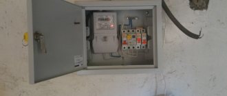
Another important point on which there is a lot of discussion is whether it is possible to connect the machine in front of the electricity meter or is this done only after it? The answer is that it is possible, and even necessary, the main thing is to buy a special box, which is sealed by energy sales representatives. Installing an input machine in front of the electric meter will allow you to safely replace the electricity control device both in a private house and in an apartment.
Here, in fact, are the rules for installing and connecting an electrical machine with your own hands. Now let's move on to the main topic of the article.
Features of connecting circuit breakers
After you decide on the type of machines, you need to connect them. If you follow certain steps, you can cope with this process without any special skills.
General recommendations for assembling an electrical panel
Here we will look at the process of step-by-step assembly of an electrical panel for a one-room apartment. First you need to prepare all the tools and components that will be used during the installation process:
- switch box;
- metal scissors;
- insulation stripping tool (stripper);
- side cutters;
- cable cutter;
- screwdriver;
- screwdriver;
- wires;
- combs;
- full set of automation.
Prices for voltmeters
Voltmeter
You should prepare your tools in advance
Assembling the shield - step-by-step instructions
Step 1. First of all, we need to place the automation on the top rail, in such a way as it should look after fixing. First we install the switch, then the UZM (protective device), after which three RCDs for different groups (leakage current 30 mA , rated 63.63 and 40 A ).
The first is for 40 A - light, the second is for 63 A - for the hob and oven, the third is for 63 A - for the remaining groups. At the end, one differential machine of type “A” is installed, because such devices are recommended by manufacturers of most household appliances.
When starting work, lay out all the necessary tools in front of you.
Step 2. Next, you need to go to the second rack and place the machines in the correct position. They must be placed strictly under a specific group of RCDs. You should start on the right side.
Thus, under each group all nine modules will be located
Step 3. Now the automation needs to be powered together. For such purposes, combs should be used in two configurations. The first is PS-1 for 12 modules. The second is PS-2 for 12 modules. Since we only have 9 modules, the excess section of the comb will need to be removed with a machine with a special disk. So, first you need to power the upper module.
Mark the required distance on the comb and cut with a disk
Step 4. When the miniature comb is ready, you will need to insert it into the automation, and then tighten the screw fastenings.
The screws of the first RCD should not be touched, because power will be supplied there by wires
Step 5. Now you need to power the lower automation using a similar principle. Here you will have to take into account some nuances. There is no need to saw off the copper together with the plastic part; they should be cut off separately. This will eliminate the need for side plugs. Thus, the plastic part will be longer than the copper one, thereby providing additional safety.
Since the automation is divided into three parts, the copper part will also need to be divided (two modules, two modules, 5 modules). After which these three parts can be used under a single plastic comb.
Installing the lower comb
Step 6. Next, you need to suppress the power from the switch on the UZM, this will allow you to check the functionality. To do this, we need to prepare two cables of 10 square millimeters - black and blue (for phase and neutral). You will need to first cut the cables to the required length, then remove the insulation at the edges, and only then connect them.
Thus, the connection between the switch and the UZM should look like this, which needs to be checked
Step 7. Check the connection is working. To do this, we need to prepare a power cable with a plug at one end and connections at the other. One side should be connected to the machine, and the plug should be plugged into the socket (in the second step).
Now you need to set the approximate value of the UZM, which will allow you to check the functionality, after which the load is disconnected, as is the power cable
Step 8. Next, you need to supply power to the first RCD, because we have already powered all the others with a comb. Here, too, it is necessary to cut the cable of the required size, why strip its ends and connect power from the RCD to the first RCD.
Next you will need to check using the same power cable
Step 9. The next step is to move all the lower machines to the right side and fix them with a limiter.
Tighten the limiter screw
Step 10. Now you need to remove the power cable and transfer the structure to the panel. Now you need to move on to the stage of installing zero buses. There are three RCDs and the same number of buses.
You will need to install busbars and connect each RCD to the busbar. This should be done using a 6 square millimeter cable. In this case, you will also need to cut the required size and remove the insulation.
We connect each RCD one by one to its zero bus
Step 11. Next, we need to power groups of machines to each RCD. Now you will need to take a cable of the same cross-section, but only red. Here, too, you should measure the required length, clean it, and only then connect it.
This is what the final connection will look like
At this stage, the process of connecting all elements of the panel is considered complete. Now you just need to tighten the screw fastenings, check the functionality of the device again, and close it with the lid. In addition, it is advisable to label the automation in order to understand the sequence of components.
Note! The load wires and power cable should be secured at the installation site.
Video - Installation of an electrical panel
Wiring
Ideally, if the machines are located next to each other on a DIN rail, then these distances can be measured simply by attaching a conductor so that the transition part from one machine to another forms a loop. This will allow the wire to exit the housing vertically.
The stripped area should be twice as long as the end of the wire, because we will have to make a small loop out of it, which will be used to connect the machine. You will need to put heat-shrink tubing on this loop or tightly wrap it with electrical tape at the place where the insulation ends. This will give our wire rigidity.
Then the loop must be inserted into the contact hole of the machine and tightened tightly. The cleaned areas should correspond to the number of circuit breakers. But we will be sure that the phase is separated correctly - the same for the apartment.
Features of connecting SIP to the input circuit breaker
Self-supporting insulated wire is widely used to transmit electricity to the home network from overhead power lines instead of conventional cable. Despite all the advantages of this conductor, connecting the SIP to the circuit breaker should not be done directly, since during operation the aluminum begins to “float” and the insulation burns. Ultimately, this leads, at best, to failure of the machine, and at worst, to a fire. The easiest way to avoid such trouble is to connect the SIP to the machine through a special adapter sleeve.
This device ensures the transition from aluminum wire to copper. You can buy it in a specialized store.
Step-by-step installation of the machine is shown in the following video:
Standards for connecting the machine in the panel according to the PUE
Government authorities have requirements for shields and their installation that are specified in the PUE and must comply with GOST 51778-2001:
- the installed shield must comply with the documentation, which clearly reflects the number of machines and their power, as well as the class and degree of protection;
- the voltage symbol should be installed on the lid - 380V or 220V;
- the phase must be connected to a fixed contact;
- material of manufacture – metal or plastic coated with non-flammable paint;
- make markings on the wires indicating the devices that are connected;
- install jumpers from bus drives between the machines;
- There must be grounding of the box body. The case must have ears so that the electrical inspector can install the necessary seals.
We assemble the shield in the apartment and house ourselves
An electrical panel in a private house, country house, or apartment performs a dual function: it provides input and distribution of electricity and creates safe operating conditions. If you want to understand a difficult issue, you can assemble the electrical panel yourself. The input machine and the meter must be installed by representatives of the electricity supply organization, but then, after the meter, you can assemble the circuit yourself (although they do not like to lose money). True, before putting the house into operation, you will need to invite them so that they are present during the start-up, check everything and measure the ground loop. All of these are paid services, but they cost much less than a complete panel assembly. If you do everything correctly and according to the standards, it will turn out even better on your own: after all, you are doing it for yourself.
Industrial or homemade shield?
Nowadays different shields are sold. All kinds of shapes and sizes. They have either a primed metal, painted base or a plastic base. There are also brushes with internal factory filling. There are designs available for individual order.
But, if the shield installer has certain skills, then it is better to install the internal parts yourself, at your own discretion. The more experience, the more competently the installation of the structure in a certain volume of the electrical panel will be completed.
Purpose of boxes for machines
Plastic and metal boxes perform the same function as distribution boards - they organize the operation of electrical equipment and serve for the electrical installation of protective devices. In the specialized literature you can find other names: box, box, shield, panel.
The main “filling” for filling the box is made up of electric machines, however, other protective devices - RCDs and difautomatic devices - can be located next to them.
There are no products for sale with pre-installed equipment. Low-voltage boxes are sold empty, and automatic protection devices are selected taking into account the characteristics of the network and installed according to the selected scheme
Large boxes contain indicators, switches, timers, differential relays. But to equip the network of a private house or one apartment, installation of additional equipment is not necessary.
If, in addition to protective equipment, an electricity meter is installed inside the box, then the panel goes from the distribution category to the metering and distribution category
Boxes are installed in apartments, on floor areas, as well as on the street, if it is necessary to connect a private home to the power supply line. They are varied in design, assembly and functions.
Instructions for connecting a two-pole circuit breaker
Now let’s try to figure out how to connect a two-pole circuit breaker to a 220 V household electrical circuit. This means that there will be 2 wires at the input - phase and zero.
The wire required for connection has 3 cores with a cross-section of 2.5 mm (VVGngP 3*2.5), therefore, the maximum permissible continuous current is 25 A.
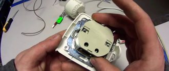
Working elements of the device
We have chosen a two-pole automatic protection device, which looks like this:
We will need four contacts, two of which are at the top (incoming), two at the bottom (outgoing). Fastening will occur using mounting screws that secure the pressure plates
There is a hint on the surface of the case - a connection diagram for the machine.
Based on the markings, we determined that the machine corresponds to the wire cross-section - C40. This means that a current of 40 A is the maximum response current of the device
The device is mounted on a metal plate – DIN rail.
If you look from the back, you can see a latch with which the machine is fixed to the DIN rail in one movement
Now that we've figured out the components, let's move on to the instructions.
Step-by-step photo instructions for connection
We turn off the voltage in the network and check its absence using a multimeter. We prepare wires that have double insulation. Three wires of different colors are hidden under the layer of external protection. The color correspondence is as follows: black – phase, blue – zero, yellow – ground.
We only need 2 wires - phase and neutral, the third (ground) will go separately. Remove the insulation 1 cm and insert the bare ends of the wires into the terminals
The phase should be on the left, zero should be on the right
Please ensure that some of the insulation does not come into contact - when heated, the cable may melt and cause damage to the device.
Carefully tighten the screws and proceed to grounding
To secure the grounding, we use a feed-through contact, which is fixed on the DIN rail in the same way as the circuit breaker itself. Insert the third wire and clamp it
The next step is to connect the outgoing wires, which are attached to the lower terminals.
In the same way, remove the insulation, insert the ends into the terminals and clamp them carefully so as not to damage the device body. Next we fix the ground wire
The connection is complete. All that remains is to apply voltage, move the control lever to the active position and check the operation.
Installing a circuit breaker in an electrical panel with your own hands
First of all, you need to decide on connecting the power wires, and only after that figure out how to connect the machine to the network. If you do not know whether the power conductors should be connected to the top or bottom of the package, please refer to the PUE requirements, which are the main guiding document for electrical installation work.
The Rules clearly state that the power cable must be connected to fixed contacts, and this requirement must be met in any circuit breaker connection diagram. In any modern device, the fixed contacts are located on top.
For installation you will need control devices and tools, which include:
- Assembly knife.
- Screwdrivers (phillips and slotted).
- Multimeter or indicator screwdriver.
So, how to connect the machine correctly? Let's consider the installation of circuit breakers in single-phase networks.
Two-phase and three-phase connections are more complex and it is advisable that they be carried out by a specialist.
Single-pole circuit breaker
The installation is carried out on a network where two cables are used for input: neutral (PEN) and phase (L). Such a system exists in old buildings. The supply conductor is connected to the input terminal of the machine, then from the output it passes through the meter, after which it is routed to the protective devices of specific groups. The supply neutral cable is also supplied to the PEN through an electric meter.
Application of one, two and three-pole circuit breakers on video:
Two-pole machine
We are considering the installation of a protective device in a single-phase network, where three conductors are used for input: phase, neutral and ground cable. The input terminals, designated on the device by numbers 1 and 3, are located at the top of the machine, and the output terminals (2 and 4) are at the bottom.
The power cable fits to input terminal 1 and is securely fixed to it. In a similar way, the neutral wire is attached to terminal 3. The phase passes through the electricity meter. Power is distributed evenly across groups of switches. From terminal 4, the neutral cable is connected to the N bus, passing through the meter and the RCD.
Connecting wires
Any circuit breaker is accompanied by a passport that states how to correctly connect the wires to its terminals. The document contains all the necessary information - from the cross-section of the cables and the type of their connection to the length of the stripped part of the conductor.
Stripping the ends of the wires for connecting household machines is done with a mounting knife about 1 cm. You can distinguish the conductors by their color markings:
- Phase cable – white or brown.
- Neutral wire – black, blue or light blue.
- The grounding conductor is green.
After stripping the end of the wire with a knife, it must be inserted into the contact clamp and secured with a fixing screw. The screws are tightened with a screwdriver. After fastening, the wire needs to be tugged a little to make sure it is securely fastened. If a flexible wire is used to connect to the package, then to increase the reliability of the connection, special tips should be used.
To ensure that the installation of machines in the electrical panel and the connection of cables to them are carried out correctly, you need to remember common mistakes and avoid them during operation:
- The insulating layer gets under the contact clamp.
- Too much force when tightening, which can lead to deformation of the body and, as a result, to breakage of the machine.
Often several protective devices are installed in a distribution board. To connect them, inexperienced specialists use jumpers.
In principle, this is not a mistake, but still in this case it is better to use a special tire cut to the required size - the so-called comb. With its help, the wires are connected to the packets in the required sequence.
Step-by-step instructions on how to connect a single-core wire
After you have purchased the RCD and all the necessary devices for installation, you can begin to work. It must be remembered that all stages of installation must be carried out sequentially and all safety measures must be taken.
Practical advice
Experienced electricians recommend installation in the following sequence:
- de-energize the shield. Check the presence of current using the indicator;
- care must be taken to ensure that no one unexpectedly turns on the electricity;
- the equipment must be firmly snapped onto the DIN rail;
- Electricians recommend connecting the device according to this principle - all incoming wires are at the top, and outgoing wires are at the bottom. This generally accepted scheme will help avoid confusion when replacing equipment;
- there should be no kinks in the wiring when connecting;
- disconnect excess parts of the cable with wire cutters;
- Carefully remove the insulation from the cable by 10 mm;
- Install the cable into the required terminals and secure it. It is necessary to monitor the clamping force - tightly twisted terminals will quickly lead to breakage of the switch;
- turn on the power supply;
- check the voltage access to the switch using an indicator.
Common Mistakes
Sometimes it happens that the power switch does not perform its functions, so you have to reinstall it again. To avoid malfunctions, you need to avoid the following installation errors:
- the insulation from the wire has come into contact. If the insulation is not removed before installation, this increases the risk of a short circuit that leads to a fire;
- connecting several wires with different cross-sections to one terminal. In this case, only a large cross-section core is tightened well, and thin wires have poor contact, which leads to melting of the housing and a fire. This happens when connecting various devices to the switch. To avoid this, you need to use jumpers between cables and devices. They are made from wires of the same cross-section;
- Do not connect copper and aluminum wires together. The device will become unusable due to the oxidation process when two metals are combined;
- You should not connect a straight wire to the terminal, but you need to bend it with a hook, which will increase the contact area and increase the performance of the device; such a cable is also more difficult to pull out of the device.
Cable cross-section for machine s16
In residential buildings, as a rule, a single-phase network is used. Therefore, wiring is chosen with 2 or 3 cores. Their cross-sectional diameter must correspond to the installed 16-amp electric machine. The maximum permissible diameter is 25 square meters. mm, but the indicator also depends on the metal of which the cable is composed. Here is their comparative characteristics:
Metal in wires
| Criterion | Aluminum wire | Copper wire |
| Cross section | From 2.5 sq. mm | From 0.35 sq. mm |
| Current conductivity | Up to 3 kW at minimum cross-section | The figure is approximately 1.6 times higher |
| Life time | 15-20 years | About 50 years |
| Strength | The wire breaks easily when bent | Due to the plasticity of the metal, the wiring can be laid at any angle. The fragility index for the same cross-section is 2-3 times lower. |
| Ease of installation | To power a modern outlet, you need a wire with a cross-section of 4 square meters. mm. The built-in terminals have a tolerance of 3 mm. That is, a connection with a nominal value of 16A is excluded. | For a similar task (16A socket), a cable with a core cross-section of 1.5-2.5 square meters is required. mm. That is, there are no difficulties during installation. |
| Oxidation | The area with missing insulation quickly oxidizes. The resistance provided by the film reduces the permissible load on the contacts. Therefore, a special quartz-vaseline paste is used. | Patina conducts current well, so it does not affect the resistance of joints. |
You might be interested in this: How do motion sensors work to turn on lights?
Terminals in socket
Despite the noticeable difference in the cost of materials (aluminum wiring is 2-3 times cheaper), most cables are laid using copper cable. When choosing the cross-section of the cores, they rely on the nature of the machine and the method of placing the wires.
For a 16A protective device, the copper core must have a cross-section of 2.5 square meters. mm. This corresponds to its maximum voltage of 21A in a walled position, 30A in an open position (it is in contact with the external environment, which means it easily gives off heat when heated).
If you take a wire with a cross section of 1.5 sq. mm, then within an hour it will overheat and fail. This is justified by the maximum permissible current of 18 A.
Installation inside and outside walls
Drawing up an electrical panel diagram
An important step in installing an electrical panel is creating its diagram. There are several explanations for this. Let's say, if you plan to repair or modernize the wiring in your apartment in the future, using the diagram you can quickly establish what each machine and part in the panel is responsible for. You will also need the diagram when accepting work as an electrician. In addition, connecting wires with such a diagram on hand is much easier. You can either draw it manually or in specialized programs, and then print it.
The electrical circuit is created in several stages. The first step is to find out what kind of electrical system is in the house, then divide all points of electricity consumption into several categories. After this, based on the existing data, a shield diagram is created
It is extremely important that the diagram used symbols, which are described in detail in GOST 21.614 “Conventional graphic images of electrical equipment and wiring in the original”
So, as mentioned above, all work begins with determining the power supply and grounding system in the apartment, since the connection of the panel will depend on this. You can find out by looking at the sign on the floor or by going to the housing office. Often, three systems TN-C, TN-S, TN-C-S are installed in residential buildings.
It is worth immediately noting that the first system was created according to old GOST standards and was used in houses that were built before 1998. The TN-C system is represented by two-core copper or aluminum wiring. A three-phase cable (L) with one conductor PEN, in which ground and neutral were combined, went to the floor distribution board. The last two systems are used in modern homes. A three-core copper wire is laid in the apartment, and a cable with three phases (L), neutral (N) and PE ground (S) is connected to the switchboard.
How to connect the phase and neutral wires
Simultaneous disconnection of phase and neutral is justified especially in situations where three-phase voltage is introduced into a house or non-residential building. In such situations, there is a greater risk that one of the phases may short circuit to zero. This is a short circuit mode to which the machine protecting this phase must respond. But in those fractions of a second while it is triggered, an overvoltage will occur in the other two phases. That is, instead of the required 220 V, there may be all 380 V - the voltage difference between the two phases with a conventional three-phase connection.
Not a single household appliance is designed for such voltage, and the more powerful it is, the more current it passes, and the greater the likelihood of it burning out due to overvoltage. Where the fuse of a low-power device immediately blows, powerful equipment will still “tolerate” a heavy load for some time, and during this time the switching power supply or transformer may fail. Therefore, it is preferable to protect equipment such as boilers, dishwashers and washing machines with two-pole circuit breakers that cut two circuits at once.
Keep in mind that phase imbalance is also harmful to the source that powers the building. A generator, a transformer booth, a substation - all this will deteriorate very soon. For such purposes, there are special three-phase circuit breakers, which, in the event of a large imbalance or failure in one of the phases, can immediately turn off all three phases simultaneously. For more critical circuits, it is recommended to connect a four-phase circuit breaker, which also de-energizes the neutral wire.
Why is it unacceptable to install a circuit breaker on the neutral wire?
I corresponded via email with Volodymirom about the inadmissibility of installing a circuit breaker on the neutral wire of the electrical wiring. For those who want to understand the intricacies of this issue, I think its result will be useful.
Volodymyr:
I'm currently installing an electrical panel in my apartment and a question has arisen. Why can’t separate machines be set to zero and phase, but only paired ones? Why “It is strictly prohibited to install a single circuit breaker on the neutral wire.”?
Answer:
When installing separate circuit breakers on the neutral and phase wires, designed for the same protection current, in the event of an overload of the electrical wiring, only one of them is likely to work. This is due to the fact that circuit breakers have a variation in the magnitude of the operating current. If the machine installed on the neutral wire is triggered, then all electrical wiring, including the neutral wire, will be under phase voltage. The phase will reach the neutral wire through electrical appliances that are turned on at this time, for example, a TV in standby mode, a refrigerator. And if a person thinks that since the machine has worked, it means that the wires are de-energized and, therefore, safe, then he can start repairing the electrical wiring and accidentally come under dangerous voltage.
That's why it's impossible. It is possible to install twin circuit breakers in household electrical wiring, but there is no point in this, only extra costs, since a paired circuit breaker costs much more. Therefore, the neutral wire is laid directly, and a machine must be installed on the phase wire.
Volodymyr:
If during a short circuit the zero-machine is knocked out faster, and the phase-man-earth short circuit continues, then the phase-machine will still be knocked out. Also, both can work approximately simultaneously. That is, the machine must be set to zero more powerful than the phase one. But there will be no disruptions to the network, only additional costs.
Answer:
If the phase-person-ground short circuit continues,” then the person will die before the circuit breaker on the phase wire is triggered. The lethal current through the human body is only 0.1 A, and a 10 A machine will only work when a current of more than 10 A flows through it. Therefore, the PUE categorically prohibits the installation of a separate machine on the neutral wire.
You can, of course, install a machine designed for a higher current on the neutral wire, but where is the guarantee that the machine will not fail? After all, the main value for any person is his health and life! Therefore, even with the hypothetical possibility of causing harm to a person, they do everything to exclude it.
Volodymyr:
I am just beginning to master electrical installation in practice, including using your recommendations. And I want to understand the technical side in order to better understand the recommendations of the PUE. So forgive me if I'm wrong somewhere.
There are two common situations: 1. Phase-to-human-earth or phase-to-earth short circuit. A phase machine will work here. Zero machine has nothing to do with it. 2. Short circuit phase-man-zero or phase-zero. A phase machine and/or a zero machine will work here. That is, if the phase machine does not work, then the zero one will break the circuit. Accordingly, the circuit breaker to zero will not be a hindrance, but only additional protection when it is not possible to install a more expensive two-pole circuit breaker that cuts off the line completely. The only inconvenience, as you wrote, if during a short circuit only zero is knocked out, then we will not know whether the phase is knocked out.
Answer:
Your reasoning is based on the assumption that the machine serves to protect a person from electric shock. But the machine is designed solely to protect electrical wiring from destruction if the current flowing through it exceeds the permissible limit. To protect people, an RCD is installed. The situations you described involving a person will not lead to the machine being turned off, since the person will die instantly if the current flowing through his body is more than 0.1 A.
According to Ohm's law, current can only flow through a closed circuit and in the event of a short circuit, it does not matter which wire is broken, phase or neutral. From this point of view, you can put one machine on the phase or neutral wire, or, if there is nowhere to put the money, sequentially, at least 10 machines on both the zero and phase wires. The wires will be protected. The machine is placed on the phase wire only so that when the machine is triggered, the possibility of a person coming under life-threatening voltage is completely eliminated.
Let me give you an example: a man decided to replace a light bulb in a chandelier and turned off only the switch, and not the machine, this is usually what they do. The wiring in the chandelier was old, and the neutral wire was touching the metal body of the chandelier. The man stood on the ground and, screwing in the light bulb, held the chandelier by the metal body with one hand. At this time, another family member decided to turn on an electrical appliance, whose insulation at the exit from the plug had frayed and the wires were short-circuited. A short circuit occurred, and only the circuit breaker installed on the neutral wire worked, and a phase appeared on the neutral wire of the entire apartment wiring. As a result, a person changing a light bulb can receive an even fatal electric shock. The machine can also work when the lights are turned on if the light bulb burns out at that moment.
PUEs are written based on accidents involving electric shock to people and it is impossible to describe all situations in which people were injured or died. You just need to follow the PUE and then the electrical wiring will never fail.
Selection of RCDs and automatic devices
The circuit breaker provides short-circuit protection, but it is not capable of detecting leakage current that may flow into the electrical equipment frame when the insulation coating is broken or through the human body. For these purposes, a residual current device (RCD) or differential circuit breaker is connected to the panel.
These devices are switching devices that constantly monitor the differential current of the electrical wiring, and if it deviates from the permissible value, a shutdown is performed. The principle of operation is clearly illustrated in the picture.
How does an RCD work?
The main purpose of these devices is to provide adequate protection in the event that a person becomes energized and to prevent fire that may be caused by a leak.
Main characteristics of the devices:
- rated current parameters (they must correspond to the circuit breaker or a higher value is allowed);
- operating voltage (220V or 380V, respectively, for single-phase and three-phase devices);
- The permissible leakage current parameter for household devices is considered safe 30mA.
In our circuit, it is necessary to install a 16A RCD with a permissible leakage current of 30mA (elements C – F). These differential protection devices do not need to be installed for hallway and kitchen lighting.
RCD for 16A
How to properly connect a differential machine
Of all types of switching devices, a differential automatic machine is considered the most practical, but at the same time expensive. It combines the functions of a circuit breaker and a residual current device. Such a device is not installed like a regular package, but requires a slightly different approach.
The differential machine is connected as follows:
- The neutral wire is installed in the upper clamping contact.
- A phase wire is installed in the right clamping contact.
It should be immediately clarified that the contact locations can be changed, but the manufacturer marks the connection sockets with the appropriate letters. And under the operating or non-working position switch there should be a special button to check the functionality of the device.
The neutral wire that passes through the differential circuit breaker cannot be connected to other circuit breakers. With this installation, the device will constantly turn off, since the currents flowing through the conductor are completely different.
There are schemes in which a differential machine is connected to a group of packagers, while in other schemes such devices are used exclusively for one consumer. When designing wiring, it is better to choose the second option, in which, when the device is triggered, only one consumer will be de-energized, and not a whole group of machines.
Methods for installing RCDs
There are two possible ways to install the device. The first option involves installing a common RCD in the electrical wiring diagram, immediately behind the meter and the machine. With one common RCD for an apartment or house, it is very difficult to find the place of current leakage through the insulation of the wires. Such a violation of insulation should be looked for throughout the apartment or cottage.
Variant of electrical wiring diagram with a common RCD and protective grounding in a single-phase network
In this case, the RCD will de-energize the entire apartment. In another option, several RCDs are installed, separately for each direction of electrical wiring, in the living room, kitchen, bedroom and children's room. This circuit of separate electrical wiring for rooms is assembled in the electrical panel in the hallway.
Several RCDs are installed in the same electrical panel. This option is of course expensive, but it has some advantages. Firstly, when the RCD is triggered, the network will be turned off in only one direction, and in the other part of the apartment the network voltage will remain. It will be easier to look for electrical damage in one room.
Electrical wiring diagram option with a separate RCD for sockets and protective grounding in a single-phase network
In a children's room, a separately connected RCD device will protect children from touching a dangerous socket faster than in the version of a common RCD. For the children's room option, an RCD with a shutdown current of less than 10 mA is installed. In the bathroom or kitchen where the washing machine is located, you need to install an RCD with a high response current (300mA - 500mA), because an RCD with a shutdown current of 10 mA will constantly turn off the kitchen.
The RCD is selected according to the optimal current for all loads in amperes. The response time of an RCD - a high-quality device - is up to 0.1 seconds, during which time an electric shock is not felt. The protection device must be checked for functionality by pressing the RCD test button once a month and after each emergency operation.
Marking
The average person pays attention only to the brand name and amperage, which the manufacturer applies to the body using laser technology or indelible paint. For professionals, all indicators are important. Depending on the machine, the number of characteristics may vary.
Marking
This is what is hidden under the numbers and letters on the front side:
- ABB, IEK, Legrand - manufacturer's logo.
- S, SH, Acti, Easy, BM, TX - linear series of modular products. The letter may be followed by various numbers.
- 6, 10, 16 and more - the maximum current value at which the circuit does not open. It is worth noting that the indicator is relevant at a temperature of +30 degrees Celsius. The product is triggered by an overload of 13-55%. If it is colder, the machine will turn off at a higher load, and vice versa in the heat.
- 230V, 400V - network voltage (single-phase or three-phase) at which use is allowed.
- 4500, 6000 or 10000 is the limit (switching capacity) at which tripping occurs during a short circuit. In this case, the device does not fail. If a short circuit occurs with a value exceeding the value, the magnetic release will not cope with it and the device will burn out. The indicator is enclosed in a rectangle.
You might be interested in: Features of a voltage divider
Short circuit limits
- 1, 2 or 3 next to the short circuit - an indicator of the speed of extinguishing the electric arc (from 10 ms, from 6 ms and from 2.5 ms, respectively). During a short circuit, the conductors heat up, which affects the insulation. The faster the machine works, the more intact the wiring and the device itself will be. The first class is usually not indicated.
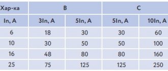
- B, C, D, K, Z before amperage - time for automatic shutdown of the device in the event of a short circuit or overload in the network. In everyday life, products with characteristics of type C are more often used, less often B and D. For example, C16 will turn off at 80-160A, and B16 at 46-80A. That is, the second one will work later. The difference is in fractions of a second.
- Wave or straight line - can be used in AC or DC voltage networks. These marks are located next to the rated voltage.
Voltage
- 50/60 Hz - frequency of oscillations in the network. The indicator is not always indicated, since most household appliances operate in one mode.
- Connection diagram. 1, 3, 5 and 2, 4, 6 - upper (supply) and lower (loaded) contacts. N - pole for connecting the neutral core.
On the side plane it is indicated:
- GOST or IEC/EN - compliance with standards (Russian or international).
- U is the operating voltage.
- Icn is the maximum breaking capacity value.
- I—electromagnetic shutdown limit.
- Uimp is the impulse withholding voltage.
- Ui is the insulation voltage.
- Deg is the degree of pollution, which depends on moisture condensation.
- Cat - application category regarding selectivity.
- Barcode or QR code is information about a product that, when read by a special device, is obtained on the trading platform.
Bar code
In addition, the manufacturer indicates the tightening torque, number of poles, and type of release. Differential machines have additional markings.
Installation and connection of elements
All modern automatic devices and RCDs have a unified mounting for a standard mounting rail (DIN rail). On the back they have a plastic stop that snaps onto the bar. Place the device on the rail, hooking it with the recess on the back wall, and press the lower part with your finger. Once clicked, the item is installed. All that remains is to connect it. They do it according to the scheme. The corresponding wires are inserted into the terminals and the contact is pressed with a screwdriver, tightening the screw. There is no need to tighten it too much - you can squeeze the wire.
They operate with the power off, all switches are turned to the “off” position. Try not to handle wires with both hands. Having connected several elements, turn on the power (input switch), then turn on the installed elements one by one, checking them for the absence of a short circuit (short circuit).
Connecting the input machine and RCD
The phase from the input is supplied to the input circuit breaker, from its output it goes to the corresponding input of the RCD (place a jumper with a copper wire of the selected cross-section). In some circuits, the neutral wire from the water is supplied directly to the corresponding input of the RCD, and from its output it goes to the bus. The phase wire from the output of the protective device is connected to the connecting comb of the machines.
In modern circuits, the input circuit breaker is set to two-pole. he must simultaneously disconnect both wires so that in the event of a malfunction, the network is completely de-energized: this is safer and these are the latest electrical safety requirements. Then the circuit diagram for switching on the RCD looks like in the photo below.
When using a two-pole input circuit breaker
To learn how to install an RCD on a DIN rail, watch the video.
In any circuit, the protective grounding wire is connected to its own bus, where similar conductors from electrical appliances are connected
Grounding is a sign of a secure network and doing so is vital. Literally
To learn how to properly connect an RCD, watch the video tutorial.
When assembling the panel yourself, please note that the input machine and the meter will be sealed by the energy supply organization. If the meter has a special screw onto which a seal is attached, then the input machine does not have such devices. If it is not possible to seal it, you will either be denied entry or the entire panel will be sealed. Therefore, inside the common panel, a box is placed in one or two places (depending on the size and type of machine), and the input machine is mounted in it. This box is sealed upon acceptance.
Individual automatic machines are installed on the rails exactly like an RCD: they are pressed against the rail until it clicks. Depending on the type of machine (one or two poles - wires), the corresponding wires are connected to them. What kind of machines there are, and how devices for one and three-phase networks differ, see the video.
After the required number of devices are installed on the mounting rail, their inputs are connected. As they said earlier, this can be done with wire jumpers or a special connecting comb. See the photo for what the wire connections look like.
The machines in one group are connected by jumpers: the common phase arrives
There are two ways to make jumpers:
- Cut the conductors into the required sections, expose their edges and bend them in an arc. Insert two conductors into one terminal, then tighten.
- Take a long enough conductor and strip off 1-1.5 cm of insulation every 4-5 cm. Take pliers and bend the exposed conductors so that you get interconnected arcs. Insert these exposed areas into the appropriate sockets and tighten.
They do this, but electricians say the quality of the connection is poor. It is safer to use special tires. Under them on the case there are special connectors (narrow slots, closer to the front edge), into which bus contacts are inserted. These tires are sold by the meter and cut into pieces of the required length using ordinary wire cutters. Having inserted it and installed the supply conductor in the first of the machines, tighten the contacts on all connected devices. Watch the video on how to connect machines in a panel using a bus.
A phase wire is connected to the output of the machines, which goes to the load: to household appliances, to sockets, switches, etc. Actually, the assembly of the shield is completed.
Where is the electrical panel for the meter and automation installed?
The first step is to decide on a place to install the shield. So, experts believe that it is better to fix it near the entrance door in the corridor, because then you will not have to lay the cable from the landing, which will greatly simplify installation.
As a rule, the shield is fixed at the level of visibility of the residents of the apartment - this will allow you to easily take readings and turn off the machines. Therefore, the installation location will differ depending on the height of the household.
Note! There are still electricians who prefer to install meters under the ceiling (as they did before). Old designs were fixed to the wall without drawers, so they were fixed at a height for safety reasons.
Electrical panel in the apartment
Any modern shields have a secure base and are closed with a lock , so strangers or small children will not be able to get there if they do not have access to the keys.
When choosing a location for installation, they also take into account where the cable of the overhead or underground power line will pass from (in an apartment or private house). You can check this information with the employees of the company responsible for electricity.
Buy a ready-made electrical panel or assemble it yourself
Now electricians not only assemble the panels themselves, but also install a ready-made factory version with all the internal contents. Such designs are even made to special order for a specific apartment.
The main point in this matter is the experience of installing branded shields. If the master has already encountered such installation, then there is no need to be afraid. In other cases, it is better to assemble the structure on site, in stages.
Prices for electrical panels
Electrical panel
Video - Assembling a panel for an apartment
Connection methods
Single-phase circuits
In order to answer the question posed earlier, one should proceed from the requirements of the PUE, which regulate the procedure for switching on the combination of an automatic machine plus an RCD. According to the provisions of this document, the protection device is connected as shown in the figure below.
Connection diagram for a single-phase RCD
When considering it, the following conclusions can be drawn:
- In a single-phase network, this device is almost always installed immediately after the meter;
- Line switches (automatic machines) are connected to its output, from which wiring is distributed throughout the apartment;
- The zero bus is connected from the corresponding output terminal of the meter to the second pole of the RCD;
Important! In this situation, special attention should be paid to the fact that the RCD is connected after the meter and before the machine with two wires: forward and reverse (this point is very important from the point of view of the possibility of its operation). You should also pay attention to the fact that the connection diagram for the uzo and the machine assumes the presence of a single-pole current switch. In this case, the neutral conductor coming from the meter or RCD is connected to a common ground bus (OGB), bypassing the machines, and from it is routed along separate lines paired with a phase wire
In this case, the neutral conductor coming from the meter or RCD is connected to a common ground bus (OGB), bypassing the machines, and from it is routed along separate lines paired with a phase wire
You should also pay attention to the fact that the connection diagram for the uzo and the machine assumes the presence of a single-pole current switch. In this case, the neutral conductor coming from the meter or RCD is connected to a common ground bus (OGB), bypassing the machines, and from it is routed along separate lines paired with a phase wire
Regarding the rules for connecting conductors to the device, the following should be noted. Like a circuit breaker, the incoming wires come from the top of the protection device, and the outlet wires from the bottom.
Three-phase network
A typical connection diagram for a three-phase device assumes the presence of 3 groups of input and output contacts, each of which forms a protection chain for one of the phases (see photo below).
Connection diagram for a three-phase RCD
Additional Information. The figure shows that in real power circuits the number of RCD input and output contacts is limited to four (three phases plus ground).
The latter is explained by the fact that the earth conductor for all three phase lines is common (it is highlighted in blue in the figure).