In order to reduce or increase the brightness of lighting today, it is not necessary to change the light bulb - just use a special power regulator. Let's look at what a dimmer is, how it works and is used in the lighting system of a house, what types of it there are and what their features are, what types of connection diagrams are used, what rules should be followed when connecting and during operation, as well as how to connect a dimmer according to the instructions.
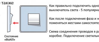
A regular dimmer can be installed instead of a standard switch Source ytimg.com
Kinds
The simplest dimmer works based on variable resistors (rheostats).
This method of adjusting lighting is considered ineffective and has low efficiency due to overheating and the need for cooling. Nowadays, manufacturers no longer mass-produce such devices; most often, radio amateurs make them themselves. The regulator, which is based on the operation of an autotransformer, produces an almost ideal sinusoidal curve at the output. But such a device is large in size and weight, and adjustment will require considerable effort.
The most popular at the moment are electronic dimmers, which are based on the operation of thyristors, transistors and triacs. It is precisely they that cannot be used with equipment that requires a sinusoidal power supply. Such regulators have another drawback: during operation they create interference that interferes with the normal functioning of radios and other sensitive devices. However, despite the listed disadvantages, electronic dimmers are used more often than others, due to their low price, small size and available additional functions.
In terms of execution, the regulator can be:
- Modular. They are installed in the electrical panel. The connection diagram for a dimmer of this design works with incandescent and halogen lamps through step-down transformers. To make them more convenient to use, the dimmer has an external button or a key switch. As a rule, a modular type of dimmer is used to regulate the brightness of lamps at the entrance gate, flights of stairs or yard lighting.
- On a cord. You can call it a mini-device that regulates the lighting of lamps that are not directly connected to the general electrical network, but are connected through a socket and plug (table lamps, sconces, floor lamps). This regulator only works with incandescent lamps.
- Monoblock. Externally, it is very similar to a regular switch. Works with different types of lamps; as a rule, this is indicated on the housing. The device is installed in the electrical circuit for a phase break; this dimmer is mounted instead of a switch.
Monoblock options are often used in apartments. In private residential buildings, it is convenient to install modular devices when you need to control the light in the adjacent area.
It is worth noting that there are still walk-through models of dimmers; they work on the same principle as walk-through switches, that is, the light can be adjusted in two places.
Rheostat as a simple dimmer
In simple words, a dimmer is an AC rheostat, but with a more complex design. The variable resistor was first invented by J. Poggendorff in the 19th century to change voltage (U, V) and current (I, A) by increasing / decreasing resistance (R, Ohm).
Depending on the type of rheostat, the value of R changes smoothly or stepwise.
To reduce the brightness of a light source, you need to reduce the voltage using a rheostat, and for this, resistance is added.
Due to the increase in R and I, the device becomes very hot and releases heat to the surrounding air. As a result, such a regulator has low efficiency and, as a result, is not used.
Dimmer classification
There are two types of dimmers - monoblock and modular. Monoblock systems are made as a single unit and are designed to be installed in a box as a switch. Due to their small size, monoblock dimmers are popular when installed in thin partitions. The main area of application of monoblock systems is apartments in multi-storey buildings.
There are several types of all-in-one devices on the market:
- With mechanical adjustment. Control is carried out using a rotary disk. Such dimmers have a simple design and low cost. Instead of a rotary control method, a push version is sometimes used.
- With push-button control. These are more technically complex and functional mechanisms. Multifunctionality is achieved by grouping regulators controlled from a remote control.
- Touch models. They are the most advanced devices and the most expensive. Such systems fit well into the surrounding interior, especially those decorated in a modern style. Commands are transmitted using an infrared signal or radio frequencies.
Modular systems are similar to circuit breakers. They are installed in junction boxes on DIN rails. Modular devices are used to illuminate stairwells and corridors. Modular systems are also popular in private homes where it is necessary to illuminate the surrounding areas. Modular dimmers are controlled by an external button or a key switch.
Dimmer power is a key parameter when choosing it. The total power of the connected devices should not exceed this figure for the dimmer. There are systems on sale with power levels between 40 watts and 1 kilowatt.
According to design features, single, double and triple modifications are distinguished. In most cases, consumers choose single dimmers.
Main types of dimmers
They mainly produce modular and monoblock dimmers, the most common are monoblock, they come in several types:
- With mechanical power adjustment. The brightness of the lighting is adjusted by a rotating disk.
- With push-button adjustment. This type of dimmer has built-in buttons to change the brightness of the lamps, sometimes there is an additional option to control the light using an IR remote control.
- Modern touch dimmers. These are the most expensive dimmers of all, they have a touch screen to adjust the light power, and are controlled via radio frequencies (via Bluetooth and wifi connection).
Below you can look at photos of dimmers that are sold in hardware stores in any city.
Ways to control dimmers
Monoblock dimmers, in turn, have several types depending on the control method:
- Sensory. These models are considered the most reliable; they do not have any mechanical elements, so there is nothing to break. Control is carried out by touching the dimmer screen.
- Rotary. Such a dimmer is controlled by a rotary dial; to turn off the lighting, you need to turn it to the extreme left position. This model is very convenient to use and widespread, it has only a small drawback - the last illumination value cannot be recorded; the switching on always occurs at the minimum brightness.
- Keyboards. This model is generally easy to confuse with a switch. To turn the light on or off, you need to flip the key, and to adjust it, you need to hold it pressed for more than 3 seconds. Some models have two keys - one turns the lighting on and off, the second regulates it. keyboard dimmer
- Turn-push. The essence of the work is the same as in a rotary dimmer, only to turn the light on and off, the rotary knob must be pressed, and then the brightness can be adjusted by turning it.
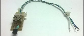
Dimmer device for incandescent lamps
Here are some photos of rotary dimmer designs.
Gunsan dimmer device
Gunsan dimmer – view from the soldering side
Makel dimmer device
Makel dimmer device - view from the soldering side
As you can see, the dimmer device is very simple, but may differ from one manufacturer to another. The main difference is the quality of assembly and components.
Requirements for installing a dimmer
When installing a dimming device, you should pay attention to several important circumstances:
- Fluorescent and energy-saving lamps are not dimmable in the standard way. Both types of light bulbs can work with a dimmer, but their service life is sharply reduced. Sometimes the life of a light bulb is reduced to 100–150 hours. In addition, the risk of damage to the dimmer itself increases.
- Dimmers require a certain minimum load. Most often its value is 40 watts. A decrease in load occurs due to the burnout of one of the light bulbs, deterioration of contacts, and the appearance of flickering with a frequency of 50 hertz. When the load drops below the minimum permissible, the protective system is triggered or the device becomes faulty.
- Dimmers are sensitive to ambient temperature conditions. At temperatures above 25 degrees, overheating is possible, which can lead to damage to the dimmer.
- The maximum permitted load on the device should not be exceeded. If necessary, it is recommended to add power amplifiers, which can be used to switch devices up to 1.8 kilowatts.
- Capacitive and inductive loads cannot be connected at the same time. This can cause damage to the device.
Additional functions
The very first dimmers had an electromechanical device, and with their help it was only possible to adjust incandescent lamps.
Modern devices provide the consumer with several additional functions:
- They can turn lights on and off according to a set timer.
- They can be installed when installing a “smart home” system; now it is very fashionable.
- Due to the fact that you can set a certain time for turning the lighting on and off, the dimmer allows you to create the so-called presence effect. This is very convenient if you have a long trip ahead and you leave your home unattended.
- Using a dimmer, you can set different operating modes for lamps, for example, make them blink.
- With the help of modern dimmers, you can control the lighting acoustically, that is, using a voice command or clapping your hands.
- The device makes it possible to control the brightness of the light remotely.
Analysis of connection diagrams
The choice of circuit depends on many factors, including the dimmer model, connection method - separate or with switches, the number of dimmers or lighting devices.
You should also take into account a very important point: different devices are used for incandescent lamps, LED lamps and strips, and low-voltage halogen light sources.
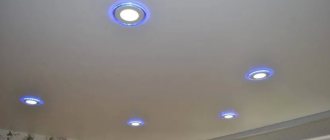
Testing a remote control dimmer connected to an LED strip. LED strips are successfully used to illuminate suspended two- and three-tier plasterboard structures
The most basic dimmer connection diagram can easily be confused with the switch installation diagram, since it actually repeats it one to one. Wiring is usually done with a two- or three-wire wire, depending on the grounding system. In new houses, it is recommended to use a wire with three cores - VVGng with a cross-section of 1.5 mm².
Three wires are pulled from the machine in the electrical panel: ground - to the metal body of the chandelier or lamp, zero - to the lamps, and phase - to the dimmer, to the input terminal
But often a chandelier has many arms, and the dimmer is used to control a group of separately located lamps. In this case, it is advisable to install two devices instead of one, so that the lighting level of two separate groups can be controlled.
The fundamental difference is in the number of load wires. One common phase is supplied to the regulator, and at the output there are two phase wires directed to different groups of lamps. Accordingly, zero is also divided by two
How does the connection occur if, instead of setting up control for conventional or energy-saving lamps, it is necessary to set up control for LEDs? Usually, complete with strips or lamps, along with a dimmer, there is an adapter from 220 V to 12 V. This can be a power supply that is plugged into an outlet.
Both wires from the converter are pulled to the dimmer, connected according to the diagram to the required connectors, and from the output terminals they are supplied to one lighting device or several lamps connected in parallel
One or more pass-through switches are often used in conjunction with a dimmer - the electrical network with such a kit becomes more advanced in terms of ease of use. The location of the switch is determined in different ways: it can be between the panel and the dimmer or between the dimmer and the lamp.
The circuitry of pass-through devices differs from a standard device, and this must be taken into account when connecting. The main attention is paid to connecting the phase conductors in both devices. Finally, let’s look at the order of arrangement of wires and terminals for a standard dimmer connection - after all, it is this that is the most popular in everyday life.
The simplest diagram that can serve as a standard for connecting a standard regulator. The phase conductor is supplied to the input, and from the output, the adjacent terminal, it goes to the lamp. The listed examples are only a small part of all possible schemes for installing the device. To make an error-free connection, you must use the manufacturer's instructions as your main guide.
Types of light bulbs
Dimmers use a variety of types of light sources: incandescent, halogen (regular and low-voltage), fluorescent, and LED bulbs. Options for connecting a dimmer with a switch differ depending on the type of lamps used.
Incandescent and halogen lamps
These light sources are rated for 220 volts. To change the lighting intensity, dimmers of any model are used, since the load is all active due to the lack of capacitance and inductance. The disadvantage of systems of this type is the shift of the color spectrum towards red. This happens when the voltage decreases. The power of the dimmers is between 60 and 600 watts.
Low voltage halogen light bulbs
To work with low-voltage lamps, you will need a step-down transformer with a regulator for inductive loads. A distinctive feature of the regulator is the marking with the abbreviation RL. It is recommended to purchase the transformer not separately from the dimmer, but as a built-in device. For an electronic transformer, capacitance indicators are established. For halogen light sources, the smoothness of voltage fluctuations plays an important role, otherwise the life of the bulbs will be sharply reduced.
Fluorescent lamps
The standard dimmer will have to be replaced with electronic ballasts (electronic ballasts) if the start is carried out by a switch, a starting glow charge or an electromagnetic choke. The simplest diagram of a system with fluorescent lamps is shown in the figure below.
The voltage to the light bulb is sent from a frequency generator of 20–50 kHz. The glow is formed due to the resonance of the circuit created by the inductor and capacitor. To change the current (which changes the brightness of the light) you need to change the frequency. The dimming process begins immediately after reaching full power.
Electronic ballasts are manufactured on the basis of the IRS2530D controller, equipped with eight outputs. This device acts as a half-bridge 600-volt driver with triggering, dimming, and anti-failure functionality. The integrated circuit is designed to implement all possible control methods due to the presence of multiple outputs. The figure below shows a control circuit for fluorescent light sources.
LED light bulbs
Although LEDs are economical, there is often a need to reduce their brightness.
Features of LED light sources:
- standard bases E, G, MR;
- ability to operate with a network without additional devices (for 12-volt lamps).
LED light bulbs are not compatible with standard dimmers. They simply fail. Therefore, to work with LEDs, special switches with brightness controls for LED lamps are used.
Regulators suitable for LEDs are available in two versions: with voltage control and with control via pulse-width modulation. The first type of device is very expensive and large (it includes a rheostat or potentiometer). Voltage dimmers are not the best choice for low-voltage light bulbs and can only operate on 9 and 18 volts.
This type of light source is characterized by a change in spectrum in response to voltage adjustment. For this reason, the adjustment of light diodes is carried out by monitoring the duration of the transmitted pulses. This way it is possible to avoid flickering, since the pulse repetition rate reaches 300 kHz.
In order for the lamp to work correctly, it contains a driver. The possibility of dimming is indicated in the product data sheet. If dimming is not possible, it is recommended to buy special devices with pulse-width control.
There are such PWM regulators:
- Modular. Control is carried out by remote controllers, remote controls or using special buses.
- Installed in an installation box. They are used as switches with rotary or push-button control.
- Remote systems installed in ceiling structures (for LED strips and spotlights).
Pulse width control requires expensive microcontrollers. Moreover, they cannot be repaired. It is possible to independently manufacture a device based on a microcircuit. Below is a dimmer circuit for LED light bulbs.
Normal frequency of oscillations is achieved through the use of a generator, which contains a capacitor and a resistor. The intervals for connecting and disconnecting the load at the output of the microcircuit are set by the size of the variable resistor. A field-effect transistor serves as a power amplifier. If the current is higher than 1 ampere, a cooling radiator will be needed.
The simplest scheme
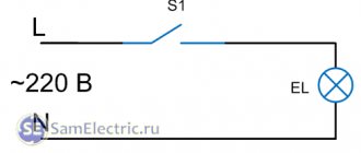
Let's look at how to connect a monoblock type dimmer. This model is the most common; it is most often connected independently and mounted instead of a switch.
The dimmer is installed in the network in the same way as a switch, with a phase break, in series with the load. A special point is that you cannot confuse phase and zero. If you connect the regulator incorrectly and set it to the zero break, the electronic circuit will be damaged and fail.
Therefore, first of all, it is necessary to determine the phase wire. The algorithm for these actions will be as follows:
- Turn off the circuit breaker that supplies voltage to the workplace. That is, it can be an introductory machine for the entire apartment, or for this room.
- Check that there is no voltage and remove the switch. Remove the key, the protective panel, disconnect the wires from the input and output terminals and remove the operating mechanism from the socket box.
- We have two wires freed up; we need to find out which of them is the phase wire coming from the junction box. Turn on the power supply again and carefully touch both wires using an indicator screwdriver. That vein, upon contact with which the window on the indicator lit up, is the required phase. Touch the second wire, the window does not light up, which means this is a wire going from the switch to the lighting fixture. Carefully mark the desired phase wire with a marker or a piece of insulating tape.
- Turn off the power supply again to connect the dimmer. The circuit is very simple; connect the detected phase to the dimmer input contact. Connect the wire that goes to the load (lamp) through the junction box to the output contact.
Triac dimmer circuit
The circuit of triac brightness controllers is basically the same everywhere, differing only in the presence of additional parts for more stable operation at low “output” voltages and for smooth regulation. Also, details are introduced into the circuit to reduce the level of interference generated by the dimer into the network.
The simplest dimer scheme
The operating principle of the circuit is as follows. In order for the lamp to light up, the triac must pass current through itself. This will happen when a certain voltage appears between the electrodes of triac A1 and G (which one - see in the datasheet, can be downloaded at the bottom of the article). This is how it appears.
At the beginning of the positive half-wave, the capacitor begins to charge through the potentiometer R. It is clear that the charging speed depends on the value of R. In smart words, the potentiometer changes the phase angle. When the voltage on the capacitor reaches a value sufficient to open the triac and dinistor (see datasheet for dinistor), the triac opens. In other words, its resistance becomes very small, and the light bulb burns until the end of the half-wave.
The same thing happens with the negative half-wave, since diac and triac are symmetrical devices, and they do not care in which direction the current flows through them.
As a result, it turns out that the voltage on the active load represents “stubs” of negative and positive half-waves, which follow each other with a frequency of 100 Hz. At low brightness, when the lamp is powered by very short “pieces” of voltage, flickering is noticeable. The same cannot be said about rheostat regulators and regulators with frequency conversion.
This is what a real light controller circuit looks like. The parameters of the elements are indicated taking into account the variation among different manufacturers, but this does not change the essence.
Practical diagram of a rotary dimmer
More details about the operation of the dimmer can be found in the video:
From words to action: how to connect a dimmer
There are standard dimmer connection diagrams suitable for home use. They are presented below:
This is what the standard and simplest dimmer connection diagram looks like. Using it you can replace one switch with a dimmer
The diagram clearly demonstrates the connection of a pass-through dimmer. You can install this between the bathtub and toilet, for example
Simple dimmer
In the most trivial case, the dimmer connection diagram is simple: into a break in the phase wire of a chandelier or other lighting device, like a switch. It performs the functions of a switch - in addition to the light control service. Simple dimmers are produced in the form factor of household switches to simplify replacement and installation. One device is replaced by another. By rotating the dimmer key, you can adjust the brightness; in the minimum position, by turning the control, you can turn off the light. More advanced models have a push-and-turn design. Adjustment occurs in the same way, and switching off is done by pressing. The advantage of this design is that it “memorizes” the set level. The rotary handle remains in the same place, and the next switching occurs at the same brightness level. Even more expensive models have touch controls, audio controls, remote control, etc.
Dimmer with switch
Also popular is a slightly more complicated circuit, but certainly very convenient, especially for use in bedrooms - a switch is installed in front of the dimmer to break the phase. The dimmer is mounted near the bed, and the light switch, as expected, is located at the entrance to the room. Now, while lying in bed, it is possible to adjust the lamps, and when leaving the room, the light can be completely turned off. When you return to the bedroom and press the switch at the entrance, the light bulbs will light up with the same brightness with which they were burning at the moment of shutdown.
Similar to pass-through switches, pass-through dimmers are also connected, which makes it possible to control lighting from two points. Three wires should go from each dimmer installation location to the distribution box. The input contact of the first dimmer is supplied with phase from the supply network. The output contact of the second dimmer is connected to the lighting load. And the two pairs of remaining wires are connected to each other by jumpers.
Diagram for connecting and controlling a dimmer from anywhere
If you want something cheaper, look at three-pin dimmers. They can also work like walk-through ones, but do not require special switches. For example, individual models from Legrand or Schneider.
Their third contact is used to connect non-fixed buttons, like a bell. Pressed once - they gave a command to turn on the dimmer. We held it longer and dimming began.
The electrical connection diagram here is as follows.
Circuit with two pass-through switches
This scheme is used quite rarely. It is in demand for organizing lighting control in walk-through rooms and long corridors. The circuit allows you to turn the light on and off, as well as adjust it from different ends of the room.
Pass-through switches are placed in a phase gap. The contacts are connected by conductors. The dimmer enters the chain in a sequential manner, after one of the switches. A phase approaches the first contact, which then goes to the incandescent lamp.
Brightness control is carried out by a dimmer. However, it should be borne in mind that when the regulator is turned off, the pass-through switches are not capable of switching light bulbs.
Characteristics and approximate cost of Legrand dimmers
Schindler dimmers are considered a good model; they are more expensive than usual for incandescent or fluorescent lamps, but their advantage is obvious; in practice, this circuit is universal. The dimmer body is made to fit a standard switch, the design is two-key, one key works like a regular switch, the second adjusts the brightness.
Tip #1. Dimmers whose design includes a regular switch are practical to use in country houses where no one lives for a long time. In this case, the lighting network is completely de-energized.
Schneider dimmers:
| Model | Power in W | Cost in rubles |
| ANYA AYA2200121 | 61-501 | 650 |
| ANYA AYA2200123 | 61-501 | 650 |
| Asfora EPH6400121 | 601 | 490 |
| Asfora EPH6500121 | 601 | 1200 |
| Asfora EPH6500123 | 601 | 1200 |
| Asfora EPH6600121 | 314 | 1000 |
| Asfora EPH6600123 | 314 | 1000 |
Some models of Schindler dimmers can be connected to any lamps, incandescent, LED and halogen via a step-down transformer. Often these dimmers are used for heating when raising chicks in a brooder using an infrared lamp. Good brooder wiring diagrams are automated, the thermal relay automatically turns on and off to maintain the required temperature.
Tip No. 2 The dimmer for the IR lamp in the brooder should have a power of at least 800W.
Dimming a table lamp
If you need to dim a table lamp or night light rather than a ceiling light, then this whole complicated procedure can be avoided. It is enough to disconnect and throw away the factory power cord and connect a special dimmer on the cord in its place.
There are plenty of models in stores and on Ali. Separate boxes without wires are also sold.
You will need them if you do not want to throw away the factory cord from the table lamp. For those who don’t want to go into such a jungle at all and rework wiring diagrams, dimmers for sockets are sold.
You plug this structure into the nearest outlet, and through it you connect the plug of the table lamp. And everything is perfectly regulated.
Rotary dimmer installation
Let's look at an example of how to properly connect a rotary dimmer:
- Start with parsing. Pull the rotary handle slightly towards you and remove it.
- Below it you will see a button secured with a clamping nut. Unscrew this nut and remove the front panel.
- There is a working part under the panel; connect the wires to the contact outputs according to the diagram discussed above. Now insert the working part into the socket box and secure it in it with screws.
- Place the front panel, secure with a nut and secure the rotary disk on top. The installed dimmer is ready for use, all that remains is to make sure the circuit is correct.
- Turn the dial counterclockwise, you will hear a characteristic click, which means the dimmer is turned off. Apply voltage to the room by turning on the circuit breaker. The lamps in the lamp do not light, which means everything is correct, because our regulator is turned off. Now start turning the dial clockwise, you will again hear a click indicating it is turned on. After this, the voltage on the lamps will begin to increase smoothly, and the brightness of the lighting will increase accordingly.
The dimmer is connected to LED lamps in the same way, with a phase break. There is only one small difference: the wire from its output contact does not go directly to the lamps, but first to the LED lamp controller.
How to install and connect the dimmer is shown in this video:
As you can see, connecting the regulators is not particularly difficult. If you know how to install and assemble a circuit for switches, then you can handle dimmers.
Connecting LED strip
Through special dimmers you can connect not only light bulbs, but also LED strips or low-voltage LED lamps.
When connecting dimmable LED lamps with remote power supply, keep in mind that the dimmer is placed in front of the driver, and not after it.
But on LED strips, in the connection diagram it goes after the 12-36V power supply.
Diagram for connecting LED lamps
For LED lamps, you cannot use the same dimmer as for halogen and incandescent lamps, designed for a specific type of load. Most of the LED, fluorescent and energy-saving lamps are not configured to work with a conventional dimmer and quickly fail. But today there are special dimmers on sale for working with this type of lamp.
There are no fundamental differences between the dimmer connection diagram for LED lamps and the diagrams described above. Its only feature is that the dimmer is installed in front of the controller of the LED strip or lamp.
Alternative uses of a dimmer
The fact that a dimmer can only regulate the brightness of incandescent lamps is the narrow-mindedness of marketers; it has many more applications.
A dimmer is not only a lighting regulator, it can be used as a voltage regulator in general, connecting any active load through it - an incandescent lamp, a soldering iron, a kettle, an iron. But the main thing is that the maximum power of the dimmer (in other words, the maximum current of the triac) must correspond to the load.
It is not a fact that the load will behave adequately and will not be in danger of failure. For example, try dimming your TV) No, better not!
In addition, you can, for example, regulate the temperature of underfloor heating. This eliminates the need to purchase a temperature controller, which costs 3-5 times more.
The downside is that there is no feedback and protection against overheating, but in many cases this is tolerable. After all, there is no feedback from the chandelier either - only through the eyes. And from the warm floor - through the legs, right? I installed dimmers on heated floors, they work great for many years.
Installation of Fibaro FGD211 dimmer with switch
The peculiarity of this model is that it is compatible with the smart home system and is controlled from a computer. There are devices that are controlled with a regulator installed in a convenient location.
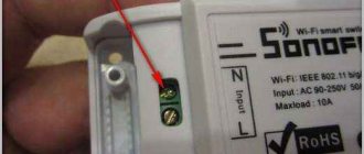
Dimmers that are installed in the mounting box to the switch are also placed in the phase wire gap, but the installation process itself is slightly different. The switch is also removed, we find the phase, and mark the wire. Next, we take the dimmer, connect terminals 0 and N with a jumper (a piece of copper wire in a sheath). We connect pieces of wire 7-10 cm long to contacts S1 and Sx.
Conductors were connected to the dimmer and a jumper was installed
The next step is to connect the regulator to the wiring. We install the phase wire on the connector with the letter L, the neutral wire on N. We insert the connected device into the installation box (we bend the wires).
Connect the regulator to power
Next, we connect the wires previously installed in sockets S1 and Sx to the terminals on the switch (any order).
Connecting the switch
We screw the switch frame into place, then put on the front cover and keys, program the system and check the operation. If you need to connect a dimmer controlled by a button, it will have two more contacts to which you will need to connect an external button.
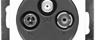
Types of devices
Depending on the scope of application and tasks assigned to the dimmer, it may differ in appearance, cost and functionality.
Below we will consider the main types of dimmers, which differ in installation, control and type of lamps.
By installation method
Based on installation features, all dimmers can be divided into several types:
- Wall. It is screwed to the wall in an overhead way or mounted in a mounting box with a diameter of 6.8 cm. With this installation, you do not need to disassemble anything, and the main requirement is the presence of wiring laid along the walls.
- Portable. Structurally similar to a tee or relay, it has connectors for connection and a plug. The device connects like a regular device with the ability to change the brightness of the lighting. You can connect a lamp, floor lamp or lamp to such dimmers. Can be used as a heating source in the presence of an IR lamp.
- Hidden (modular). This type of installation is relevant for modular structures that are mounted on a DIN rail in a panel with automatic machines. The power first goes to the dimmer, from which the wires branch out to the light sources. The advantage of this design is that you can replace several individual devices with one device with multi-channel control. To adjust the light, you need to open the flap and make settings.
- Built-in. Combines the advantages of hidden and wall dimmers discussed above. Such equipment is mounted in partitions, and a control panel is mounted at the top. Externally, the device has much in common with a switch. The difference is that there are elements of smooth control here.
- Suspension. It is small in size and is mounted in the section of the light bulb's power wire. The use of such a dimmer allows you to adjust the light even in the absence of an option.
By management
All dimmers differ in the way they are controlled:
- Rotary. Structurally, they consist of a casing and a wheel, the movement of which changes the brightness. Changing the position of the regulator allows you to turn the lighting to maximum or turn off the light altogether. This version of the dimmer has no memory, so after turning off all settings are reset and you have to set them from scratch.
- Push-button. They have much in common with conventional switches. They consist of a pair of buttons responsible for turning on and brightening the lighting. To select a parameter, you must press, hold it pressed, or release the control element.
- Turn-push. Structurally, they have much in common with a switch, in the center of which a round control element is installed. To adjust the brightness you need to press on it, and to turn it off you need to press the button. After switching off, the device retains its settings, making it easier to use.
Schneider Electric Blanca - Sensory. The principle has much in common with the push-button version. The difference is that to change the brightness, you just need to touch a specific button (up/down arrow), hold it, or release it. To enable/disable a separate button or a combination of them is used. There is a mode saving function.
By type of signal transmission
Most modern dimmers have remote control capabilities.
The following options are possible here:
- Infrared. Such devices have an IR sensor directed towards the receiving device. Dimmers with such control are inexpensive and only work in direct line of sight of the signal. Even with a thin barrier, control becomes impossible.
- Radio signal. Unlike the option discussed above, the waves easily bypass obstacles, which allows you to adjust the light even from another room.
- Wi-Fi. The remote control is a phone or tablet PC with software installed on it from the dimmer manufacturer. To issue a command, you can remotely adjust the lighting parameters. The main thing is that both devices are connected to the Wi-Fi network. Regulation is available simultaneously to several people who have a smartphone with the desired program. For example, all family members.
- Acoustic. These dimmers are controlled by voice command. The memory of the dimmer contains control elements (clap, words), to which the dimmer reacts and executes the command. At this stage, such devices are still being improved to increase efficiency.
By type of lamps used
Each lamp type uses a compatible dimmer model. If the manufacturer claims to support several types of light sources, a “smart” controller is mounted inside the equipment, and this affects the cost.
There are two types of devices here:
- For voltages up to 230 V. They are suitable for simple / halogen lamps. There is a special regulator inside that allows you to work both with a 220 V strip and with diode lamps.
- For 12/24 V. For such devices, a step-down transformer is used.
In terms of supported bulbs, incandescent dimmers generally work for halogen bulbs and some LED bulbs.
Modular dimmers - connection diagram
In addition to indoor models, there are also modular units. They are mounted on a DIN rail in the electrical panel.
Through them you can control the lighting in the entrance, staircase or on the street. They come complete with a remote button or switch in the form of a key. By pressing and holding it, the brightness is adjusted.
Such a dimmer is already switched to phase-zero, and the control button is connected with a separate wire from it. The diagrams here look like this:
On the Hager EVN modular dimmer, the connection order is as follows. The L and N contacts are supplied with phase and zero respectively.
The output to the light bulb is removed from pin No. 4.
Through contact No. 3, a control signal is supplied from the connected keys.
What if you don’t want any dimmers or switches on the wall at all, but at the same time want to be able to adjust the brightness of the lighting? And in this case there is a way out.
Use a dimmer installed directly into the installation box.
It is controlled both from buttons and from the remote control.
You can order one for yourself here. The remote control for it is from here. A good video review of this device can be seen below.
Dimmer operating principle
Previously, in lighting networks, a rheostat (variable wire resistance) was connected in series with the load, changing the current in the circuit, the power changed, and the brightness of the lamp changed accordingly. This method is not economical; the remaining power was dissipated as heat on the rheostat structure. With the advent of semiconductor devices, diodes, triacs, transistors and theristors, it became possible to more economically control this process. Let's consider the operation of the simplest circuit using a diode bridge and a thyristor.
The simplest circuit of a thyristor dimmer
This circuit allows you to change the voltage on the load from 0 to 220V; the lamps are connected to the network through a diode bridge. While the teristor is closed, no current passes through the diodes, a rectified voltage is applied between the anode and cathode of the teristor, at the same time it is applied to the charging circuit C1;R2;R1; when the capacitor is fully charged, the teristor opens. In this case, the diagonal of the bridge is closed, alternating current will pass through the load, in the diagonal of the bridge the current flows only in one direction, this allows the use of a theristor.
Tips for selection and use
Often a dimmer is purchased to significantly reduce electricity bills. It should be understood that big savings will not be achieved, but it will still be possible to reduce costs by 15-17%. When choosing a model, pay attention to the design. Manufacturers offer various collections that differ not only in technical characteristics, but also in external design - color, shape, size of the decorative panel
Remember that the control mechanisms are sensitive to any excess of the temperature in the apartment; it is usually limited to a value from +27 to -28 °C. For normal operation of the device, a minimum load of 40 W is required, otherwise the working mechanism will quickly fail.
If you try to connect the dimmer to lighting fixtures not listed in the manual, it will not work. The power of the device must correspond to the total power of the lamps.
Step-by-step replacement instructions
Before work, turn off the power supply. You can replace the switch with a dimmer yourself. You need to follow the replacement instructions - turn off the lighting, remove the switch and install the regulator. Before performing any electrical work, turn off the power supply to the room. To do this, you need to turn off the electricity in the panel on the site or inside the apartment.
First of all, you should remove the decorative panel from the switch. Then the internal mechanism connected to the wires is pulled out. The last step is to disconnect the conductors. The cores must be carefully pulled out of the terminals, keeping them intact.
If the wires are in good condition, there is no need to perform preparatory procedures. You should study the dimmer connection instructions, which outline the basic requirements and wiring diagram for the wires. Then you need to apply power and check the functionality of the regulator. If connected correctly, the brightness will gradually increase and decrease.
A dimmer is a convenient device for adjusting the brightness of lighting. It can be used either instead of a classic light switch or together with it. Having basic electrical engineering skills, you can independently connect the dimmer to the light bulb. To do this, you need to observe the correct connection of conductors and safety precautions.