Ethernet relay control RODOS-8
- The built-in web interface allows you to control the relay and make device settings from any device via a web browser;
- Direct http requests (http GET); allows you
- creating scripts for various operating systems to solve typical problems; relay control via desktop shortcuts;
- implementation of relay controls on the user site;
Installation and connection
For the relay to work, it needs 220 V power. From this fact it follows that the automation can be disguised anywhere without difficulty. (on the ceiling itself, walled up under a lighting fixture or decoration, in a switch box, in sight for manual control, etc.).
For surface installation it has 2 mounting holes (on the back). The connection diagram is implemented as follows:
- Terminals L and N on the input side (the designation is indicated directly on the front side of the relay) are supplied with phase and zero from a 220 V supply;
- The cross-section of the connected cores must fit within 1.5 square millimeters. Otherwise, there will be problems with attaching the cores to the terminal blocks.
- At the other end of the wire there should be a plug, which in the future will be connected to a 220 V network.
As an example, a power cable of the PVS brand (3 wires - brown, blue, yellow) was used for connection.
Install and tighten using a screwdriver:
- Brown - phase to terminal L.
- Blue - zero to terminal N.
- Leave the yellow one unconnected.
On the reverse side (output) connect the adjustable device in the same way.
After installation, cover the connection area with protective covers. The teeth will allow you to fix the connected wires and protect them from breaking. After installing the cover, tighten it with the mounting screws.
To connect a load of up to 10 A, the relay can be connected according to this scheme.
If the rated current exceeds 10 A, in order not to burn the device, it is recommended to use a contactor in the circuit.
Using the contactor you can control:
- Single-phase and three-phase load;
- Direct and alternating current.
After connecting to the power circuit you can:
- Operate manually;
- Pair your smartphone with the relay and control it via WiFi.
An example of connecting a contactor to an IP relay RODOS-8
To control loads over 7A/250V, you can purchase a CONTACTOR for this device.
Fig. 1 – Example of connecting a contactor to an IP relay RODOS-8
IP relay RODOS-8 is a power load switch with a built-in electromechanical monostable relay type 1C (changeover contact). There are 3 contacts from the built-in relay to the terminal block:
- COM – “general”;
- NO – “normally open” – closes to “COM” when the relay is turned on;
- NC – “normally closed” – closes to “COM” when the relay is turned off.
Communication with the device is carried out using the 10Base-T standard (the maximum permissible segment length is 100 meters).
Switching the built-in relay is accompanied by the corresponding LED on the side panel of the device turning on/off. The green LED on the device flashes approximately 2 times per second to indicate normal operation.
If necessary, all device settings can be reset to default values by pressing the special “RESET” button.
Fig. 2 – Front panel of IP relay RODOS-8
Fig. 3 – Rear panel of IP relay RODOS-8
Fig. 4 – Relay with changeover contact in IP relay RODOS-8
Fig. 5 – Switching power converter to IP relay RODOS-8
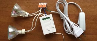
Connecting a remote lighting control system
First, choose a connection method. In the case of using a switch that acts as a replacement for a regular one, you need to take into account the connection of the line to it and the consumer. If a separate, built-in power unit is used, then a power cable to the lamp or socket itself is sufficient.
Selecting a Wi-Fi switch
Wifi switch
The main parameter required in the case of a WIFI switch is its maximum throughput. The amount of consumer withstand current should be 1.5 times higher than actual use. That is, if there are 6 lamps of 100 W in a chandelier, then the breaker should be able to pass through 6 x 100 x 1.5 = 900 W.
If this condition is not met, the risk of a fire in the room increases several times.
Again, the wiring must also match the current draw.
Selection of power modules
Here, in addition to the already mentioned power consumption, as in the case of switches, it is necessary to take into account the range of action of the radio buttons and the power unit.
Of course, many manufacturers write about 50 meters or more, but the reality is that these parameters are indicated only for cases where there are no obstacles between the equipment. That is, reinforced concrete walls separating the radio button and the power module, for example, will greatly reduce this distance.
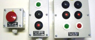
Radio switch with three power blocks
System connection procedure
It all depends on the equipment used. If an intermediary docking station is used, the connection is configured to it. In the absence, but in the presence of devices that allow direct control via WIFI, a connection is made to each of them.
The setup process is fully described in the documentation that comes with the switch or general control unit. The only point worth mentioning is that the radio buttons themselves, in the case of using built-in power modules, also need to be “linked” to a specific line breaking node.
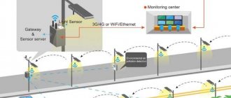
Setting up an Internet network and Wi-Fi
One of the types of network gateways
If the system contains a common docking station, then it must be connected to a home network router, via the included cable or, after the initial settings, using WIFI.
The configuration change itself is made via the web interface from a computer or phone. The documentation indicates the address to which you need to make an initial call, then you just need to modify the parameters on the screen and save them for them to take effect.
If there is only one switch or power module and it has the direct ability to connect WIFI clients to it, then the default parameters for the network contact can be found in the instructions, and after connecting to it, you can configure it within the limits of its versatility.
The docking station will not only provide the opportunity to control consumer devices from a nearby phone, but also control them or lighting from a smartphone via the Internet.
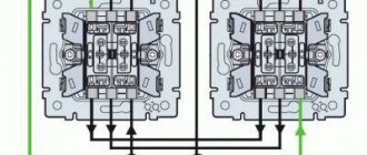
Installation of a remote switch
Installation of a radio button
The placement of the remote switch itself depends on its type. In cases where a radio button plus a power module is used, the switching unit itself is mounted on the line break (or rather, the conductors are first connected to it, and then go from it to the consumer), and the switching device is attached in any convenient way to the desired location.
If a touch contact with radio control capability is used, then it must be installed on a prepared platform (or recess), where the power cable from the panel and the current consumer line are led.
Installing software on a smartphone
Software for Android or iOS smartphones, as well as computers that control power or light control devices, can be found both on Google Play and on the manufacturer’s website. It is not necessary to use special software - the web interface functions typical for such devices may be sufficient.
Built-in Web interface
Main menu of IP relay RODOS-9
To gain access to the device’s web interface, you need to open any Internet browser and enter its IP address (default 192.168.1.20), after which you will be taken to the main page displaying the status of the built-in relay.
By clicking on the “Main” button in the upper left corner of the screen, you can return to the main page from any section of the web interface.
The “Setup” button opens the device settings section and control of the built-in relay. This section is protected by a login and password (default login/password admin/admin). To work correctly with the device via the web interface, JavaScript must be enabled in the browser.
Fig.6 – Ethernet relay RODOS-8 – main page
Relay control section
Fig. 7 – Ethernet relay RODOS-8 – relay control page
In this section of the web interface, the relay built into the device is controlled. There are 3 options available:
- “ON” – turn on the relay;
- “OFF” – turn off the relay;
- “SET” – send a pulse with the duration specified in the settings section (switching on and then switching off).
Section for relay settings and displayed names of the web interface
This section allows you to set the names of the built-in relay and the device itself, displayed in the browser. To set new names, you need to enter them in the appropriate text boxes and click the “Save” button. The allowed length of the relay name is 0...8 characters; The allowed length of the device name is 0…13 characters.
The “off” and “on” buttons determine the state of the built-in relay after power is applied to the device; If the “mem” button is turned on, then when the device is turned on, the state of the relay that was before it was turned off will be reproduced.
A tick in the “Secure management” field blocks access to managing built-in relays via HTTP GET requests outside the zone protected by login and password.
In the “SET Pulse duration” field, the duration of the pulse supplied by the SET command (Relay Control section) is specified in seconds. Acceptable values are 1…999.
Fig. 8 – Ethernet relay RODOS-8 – relay settings page and displayed names of the web interface
Network settings section
This section is intended for managing the device’s network settings, as well as setting a login with a password for the protected settings zone and relay control. The allowed length of login and password is 6 characters.
Fig. 9 – Ethernet relay RODOS-8 – network settings page
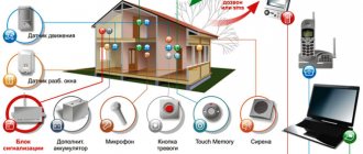
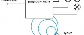
Controlling light from a distance - what is it, circuit options, tasks to be solved
The ability to turn on and off lighting in the house and in the surrounding area from a distance is carried out using special technical devices. There are several options for such control schemes:
- General.
It is used when several lamps need to be turned on or off at the same time. This control scenario is necessary, for example, when there is no time to go around and check all the rooms before leaving the house.
To complete the task, so as not to open the common electrical panel every time, a special controller is used. It is installed at the entrance and combines a group of main lamps that need to be de-energized upon leaving the house.
A special unit can simultaneously control several lamps Source siteapi.org
- Remotely.
Technically, remote switching on of light is carried out in several ways:
- Push-button remote control. Suitable for turning on and off lamps mounted in several tiers, as well as for controlling outdoor lighting - illumination of the house, on the site, in a bathhouse, barn, gazebo, greenhouse and other structures.
- By computer. Using a special program that interacts with the smart home system, you can turn on and off the main lamps of the house and the surrounding area. Moreover, this method is accessible both directly from the home itself and from any other place via the Internet.
- Mobile gadget. A special mobile application allows you to perform a similar procedure from a smartphone, tablet or laptop.
In addition, the lighting can be turned on and off by sending a special code SMS from a regular mobile phone.
Smartphone software effectively controls the light in the house Source lightcomplect.ru
- Automatically.
Lighting devices turn on depending on the signal coming from 3 main types of devices:
- Sensors. In most cases, an IR motion sensor is used. Ultrasonic, microwave and other types of detectors can also be installed.
- Photo relay. The lamp begins to work only when natural light decreases to a certain level, that is, at dusk.
- Timer. The device turns on strictly according to the specified schedule.
The operating principle of the devices is based on the interaction of two main modules - a sensor that sends a signal to a specific event, and a receiver that detects the signal and sends a command to turn on the lamp.
See also: Catalog of companies that specialize in electrical work of any complexity
Problems to be solved
Remote control of light from a remote control, sensor, timer, computer or gadget allows you to solve the following number of problems:
- Comfortable lighting control. It will take less time and effort to turn the light on or off.
- Energy saving.
- Stabilization of illumination characteristics.
- Combining a group of lighting devices into a single system.
- Automation of light control.
The light control system integrates and controls all the lamps in the house Source amperasmart.ru
- Turning lighting on and off according to a given scenario.
- Increased security level. Eliminates the need to walk through the dark to reach the light switch.
- Strengthening security. Turning on the lights for movement in most cases deters intruders who want to enter the territory and the house.
- Possibility of integration with other systems for controlling home electrical equipment.
On a note! To control the light inside the house, it is enough to use IR sensors. Their range does not exceed 10 m, which is quite enough for a room. However, if you need to install a similar system outside the home, it is better to use radio wave analogues that can operate over several tens of meters.
Relay control via direct http (GET) requests
Device control via HTTP GET requests is performed by accessing specific files located on the device domain. All files for relay control are by default located in the protected zone “https://protect/...”, access to which requires authorization.
But by unchecking the “Secure management” field in the “Relay config” settings, the user can open access to files for managing relays located outside the secure area, for access to which authorization is not required.
Relay numbering when accessed via http GET requests starts from zero.
Example of control via the Windows command line and the wget.exe application
Fig. 10 – Controlling the RODOS-8 relay via the Windows command line and the wget.exe application
Source code of the RelayControl.exe executable file
echo off cd %~dp0 wget.exe -q -O- “https://admin: [email protected] /protect/rb0n.cgi” pause>nul
Example of control via Linux terminal
Fig. 11 – Controlling the RODOS-8 relay via the Linux curl terminal https://admin: [email protected] /protect/rb0n.cgi
Main advantages of control systems
Initially, the ability to remotely control lighting was only available in expensive and advanced smart home systems. Now the situation has changed and the function has begun to be implemented in simpler control complexes and blocks.
One of the main advantages of the control system is the ability to control groups of devices or individual light sources from a single client interface
Remote equipment has many useful qualities and advantages.
Among the main advantages are the following important positions:
- Ensuring the security of the premises in the absence of owners . System control is available through any modern gadget with Internet access. Property owners, when going on a business trip or vacation, can program the lights to automatically turn on/off, simulating the presence of residents in the house or apartment.
- Saving money and materials during installation . To install the simplest remote control system, you do not need to buy a cable, hire workers to groove the walls, and spend additional money in the future on replacing wires.
- Independence from voltage surges and emergency power outages. In many advanced control systems, the cabinet, automatic machine and touch switch with the remote control are in contact via radio waves and do not require the presence of an energy resource in the network.
- Financial feasibility . Remote control units allow you to use electricity as efficiently as possible and illuminate only the necessary objects, rooms and territories at any given moment. With this approach, the efficiency of the lighting system increases, and energy consumption decreases without compromising the comfort of property owners.
These parameters make the systems a relevant and popular technical solution for remote control of lighting equipment.
Device management via UDP
Relay control
RODOS-8 supports control of the built-in relay via the UDP protocol. Command structure for controlling a relay (square brackets are not placed in the command):
| [login] | [space] | [password] | [space] | k[N]=[action] |
Legend:
- [login] – login from the protected zone, set in the network settings section of the Web interface;
- [password] – password for the protected zone, set in the network settings section of the Web interface;
- [space] – space;
- [N] – number of the relay on which the operation is performed; numbering starts from “1”;
- [action] – action that is performed on the relay: 0 – turn off the relay (closing the normally closed and common contacts (NC and COM);
- 1 – turn on the relay (closing the normally open and common contacts (NO and COM);
- 2 – send a pulse of a given duration to the relay.
Example commands:
| admin admin k1=0 | Turn off the built-in relay. Login and password for the protected zone “admin” |
| admin admin k2=1 | Turn on the relay. Login and password for the protected zone “admin” |
Example of relay control from the Linux console
Fig. 13 – Controlling the RODOS-8 relay via UDP via commands from the Linux console echo -n “admin admin k1=1” > /dev/udp/172.16.0.150/8283
An example of controlling a relay from the Windows command line via PowerShell
Fig. 14 – Controlling the RODOS-8 relay via UDP via commands from the Windows command line
Example of PowerShell code (turn on the relay, then turn it off after 500 ms; device IP address 172.16.0.150, port 8283). The script text is saved in a separate file with the extension “.ps1”.
File "Send-UDPMessage.ps1":
[String]$Hostname = "172.16.0.150" [Int]$Port = 8283 [String]$Relay_1_ON = "admin admin k1=1" [String]$Relay_1_OFF = "admin admin k1=0" $udpclient=new-Object System.Net.Sockets.UdpClient $b=[Text.Encoding]::ASCII.GetBytes($Relay_1_ON) $bytesSent=$udpclient.Send($b,$b.length,$Hostname, $Port) Start-Sleep - Milliseconds 500 $b=[Text.Encoding]::ASCII.GetBytes($Relay_1_OFF) $bytesSent=$udpclient.Send($b,$b.length,$Hostname, $Port) $udpclient.Close()
Run the generated PowerShell script from the command line
@echo off powershell -executionpolicy bypass -File %~dp0Send-UDPMessage.ps1 pause>nul
Relay control via Hercules SETUP terminal program
Fig. 15 – Control of the RODOS-8 relay via UDP via the Hercules SETUP terminal program
Getting a list of connected devices
In order to receive a list of RODOS-8 devices operating on the network, you must send the character “R” (without quotes) to the network broadcast address on port 30303. In response, the device will return the “Device Name” specified in the web interface, as well as IP and MAC addresses.
An example of getting a list of connected devices on Linux
Fig. 16 – Receiving a list of connected RODOS-8 devices via UDP echo -n “R” | socat - UDP-DATAGRAM:172.16.0.255:30303,broadcast
Example of obtaining a list of devices via PowerShell Windows
Fig. 17 – Obtaining a list of connected RODOS-8 devices via UDP
PowerShell executable file “Send-UDPMessage.ps1”:
$Hostname = "172.16.0.255" $Port = 30303 $GET_IP = "R" $endpoint = new-object System.Net.IPEndPoint ([IPAddress]::Any,$Port) $udpclient=new-Object System.Net. Sockets.UdpClient $udpclient.Client.ReceiveTimeout = 1000 $b=[Text.Encoding]::ASCII.GetBytes($GET_IP) $bytesSent=$udpclient.Send($b,$b.length,$Hostname, $Port) try { while ($true) { $content = $udpclient.Receive([ref]$endpoint) echo ([Text.Encoding]::ASCII.GetString($content)) } } catch {} $udpclient.Close()
Running a PowerShell script from the Windows command line. Executable file "UDPstart.cmd"
@echo off powershell -executionpolicy bypass -File %~dp0Send-UDPMessage.ps1 pause>nul
Getting a list of devices through the Windows terminal program
Fig. 18 – Obtaining a list of RODOS-8 devices through the Windows terminal program