Push-button control station
The main purpose of push-button stations is remote control of various electrical installations and devices. Most often, they are used in control systems for three-phase synchronous and asynchronous motors.
Thanks to their use, the ventilation system operator does not need to go up to the fan location area - the post can turn on and off all electrical devices from his workplace.
In this case, the push-button stations are combined and located on one panel, called the control panel.
Functions performed by push-button stations, which include:
- Turning on and off electrical appliances and devices.
- Switching the direction of rotation of the rotor of electric motors (reverse).
- Manual, emergency shutdown of electrical installations,
They are made with different functionality and in a variety of designs.
Push-button control stations are not intended for use in high-voltage circuits. Their main purpose is to work in alternating current electrical networks with a voltage of up to 600.0 volts or direct current with a voltage of up to 400.0 volts.
Technical parameters of the control station
Typically, such devices have a small number of characteristics, some of which are not technical. The latter include the name of the post, its type and a note on the device.
They may also have the following technical parameters, according to which they are selected:
- rated current in amperes (usually 6 A);
- voltage in volts (220, 250 V and more);
- design option according to the type of control element;
- number of electrical contact elements;
- climatic characteristics according to the relevant GOST.
Note! Control elements can be of the following types: cylindrical, mushroom-shaped, mushroom-shaped with fixation in the “pressed” position, cylindrical with a lock and fixation.
You may be interested in: Installation and connection of heated floors
Portable version with indicator
Connection
In most cases, a push-button station is used to switch the power supply to magnetic starters that are installed in the control circuits of asynchronous AC motors.
and controlling it using a three-button post is shown in the figure above, where the following notations are adopted:
- “Start forward/backward” and “Stop” are buttons on the control panel.
- KM1 and KM2 are coils of magnetic starters that perform direct and reverse activation of the electric motor.
- KM1.1…KM2.3 contacts of magnetic starters.
The scheme works as follows:
- When you press the push button “Start-forward” , power is supplied to the coil of the first magnetic starter (“KM1”); the group of normally open contacts KM1.1 closes, supplying power to the motor windings.
- Normally closed contacts “KM1.2” disconnect the pusher contacts “Start-backward”, blocking the activation of the coil of the magnetic starter “KM2”, and normally open contacts “” close parallel to the “Start-forward” button.
- When you press the “Stop” pusher, power is not supplied to the coils of both magnetic starters (“KM1”; “KM2”), they are turned off, the contacts “KM1.1” and “KM1.3” open, de-energizing the electric motor.
- When you press the “Start-Reverse” button, the contact closure procedures are similar, only they are carried out in relation to the second magnetic starter “KM2”.
Design features
Depending on the number of controlled electricity consumers, the posts can be two-button ("Start" and "Stop" pushers) and multi-button. In addition, when performing electrical and electrical work, single buttons are used, which the user can independently install on any control panel.
Push-button stations are mounted in a plastic or metal case that has mounting holes for installing the fittings in a place convenient for use. A separate group consists of push-button stations designed to control hoists (PKT series), beam cranes and overhead cranes with ground control.
The main functional element of the device that starts, stops or switches the modes of the electricity consumer is a push button - an electrical switching fixture with manual control.
Today, control panels use two types of pushers:
- With self-return , in which the button returns to its original state due to a return spring installed on the pusher on the bottom side.
- Pushers with position fixation (self-holding), which close the contact and hold it until pressed again.
The most common is a two-button starting valve, the design of which is shown in Fig. 2. The remote control consists of a housing 1 and a front panel 2, which are connected to each other by screws 3. The buttons are painted in different colors and control a pair of contacts located inside the housing.
In the free state of the “Start” button, its pair of contacts is open, while the “Stop” button, on the contrary, is closed. When you press the start button, its contacts close.
There are a huge number of switching schemes for various electrical systems and devices with just two buttons. However, most of them do not provide direct voltage supply to the consumer, but through the contacts of a magnetic starter, which are designed for high currents and voltages.
The pushers themselves have different shapes and colors, which in fittings produced in Russia are usually reflected in their symbol.
According to their shape, pushers are divided into:
By pusher color:
- Stop buttons are usually colored red (“R”) or yellow (“G”);
- “Start” pushers can be black (“B”), blue (“C”), green (“Z”) or white (“B”).
Types of push-button control panels
Today, on the electrical equipment market, a fairly large number of different push-button remote controls are produced that control electrical equipment.
However, functionally and structurally, they are all identical and differ in design and brand. All model lines of this type of electrical fittings can be supplied in various placement categories and different designs.
Typically, these two parameters are reflected in the symbol of a specific model. Russian enterprises produce the PKE, PKT and PKT series for installation in industrial equipment control systems.
The PKE series has found the widest distribution in control circuits of wood and metalworking machines and industrial complexes.
The permissible operating parameters of these devices are as follows:
- Maximum value of switching voltage: constant – 400.0 volts; alternating (frequency 50.0 or 60.0 hertz) – 660 volts;
- Switching current – 10.0 amperes;
- Maximum number of actuation cycles – 5×10 6 .
The symbol for push-button stations of the PKE series is shown in Figure 3, in which the following characteristics are indicated by numbers:
- 1 – serial number designation;
- 2 – characteristics of the installation method (built-in or overhead);
- 3 – degree of protection category;
- 4 – body and panel material (metal or plastic);
- 5 – number of controlled contacts (the figure shows the designation for two contacts);
- 6 – a parameter indicating product modernization;
- 7 – category of accommodation and the corresponding climatic modification.
Post types
There are many different push-button remote controls on the electrical equipment market that can be used to control equipment and machines. It is worth noting that the differences between many of them can be traced mainly in the design of the case and the brand, while the functionality and design of many are completely identical.
Therefore, from the manufactured devices, only the main ones with justified technical differences are distinguished:
- PKE, with the help of which the control of metal and woodworking units for industrial and household purposes is carried out;
- PCUs intended only for industrial equipment where there is no threat of explosion;
- PKT used for units with a lifting and loading mechanism.
Cost indicators
The cost of Russian push-button posts is quite low and depends primarily on the number of buttons , category of placement and climatic design. Devices in a metal case are slightly more expensive than analogues installed in a plastic case.
For example, the price of two-button devices “PKE-222-2” is in the range of 250.0...280.0 rubles. A similar device with a mushroom-shaped “Stop” button will cost a little more – 380.0 rubles.
The price of one-button posts does not exceed 150 rubles. The six-button telpher remote control “PKT-60” costs 300.0 rubles. A device with a similar number of buttons and electrical parameters, equipped with a key (“foolproof”), will cost 200.0 rubles more.
Purpose of the general control station
These devices are used in various fields, but most of them are industrial. Take, for example, the control station of a hoist. With its help, you can not only control the operation of many mechanisms, but also raise or lower the crane, influence elevators and escalators, etc.
If we talk about simpler devices, then standard posts are most often used to control various power devices (electric motors). Usually this is a “Start-Stop” type starter, which has only two buttons with the same names. This applies not only to magnetic starters, but also to other types of relays.
Buttons and posts
Modern control buttons and push-button posts - types and types
For remote control of various electrical devices and machines, control buttons and push-button stations are used. Most often, these means are used to control equipment that uses electric motors as drives. Thus, the operator does not need to climb onto the crane beam in order to bring the hook to the desired place on the workshop territory; instead, he just needs to press the appropriate button on the control panel, and the crane itself will go where the operator indicates.
In a similar way, the power supply and operating modes of machines, fans, pumps, etc. are controlled. Buttons and push-button stations can be located at the operator’s workplace, forming a specialized remote control for solving specific problems related to the control of equipment at a given enterprise.
A button is an electrical command device consisting of a push-button (contact) and drive element and is intended primarily for manual remote control of electromagnetic devices.
Buttons are used in AC circuits with a voltage of no more than 660 V and DC circuits of no more than 440 V. There are two types: monoblock, in which the contact element and drive are mounted in a single block, and double-block, in which the drive (pusher, handle, lock with a key) is installed on a separate plate, and the push-button element is mounted on the base under the drive element. Buttons can have from 2 to 8 contacts, and the number of normally open contacts is usually equal to the number of normally closed ones.
After the pressure on the drive element stops, it, together with the contacts, returns to its original position under the action of return springs. There are buttons without self-return - with a mechanical or electromagnetically controlled latch. Modern button designs use bridge-type moving contacts with a double circuit break. The contact material is silver or metal-ceramic compositions.
The continuous current and switched alternating current do not exceed 10 A. The pressing force on the button drive is 0.5 - 2 kg. For safety reasons, the button pushers that execute the “stop” command protrude 3–5 mm above the level of the console cover where they are installed, and the buttons that execute the “start” command are recessed to the same distance.
According to the degree of protection from environmental influences, buttons are distinguished into open, protected and dust- and water-proof versions. Several buttons built into one shell or installed on one cover form a button post (station).
Push-button stations are designed to turn electrical devices on and off, to change the direction of rotation of drives in devices, for manual emergency shutdown of equipment in emergency situations, etc. - depending on the purpose of a particular electrical equipment.
In general, it can be noted that for different tasks, push-button stations are made in different housings and with different numbers of buttons, however, one feature is fundamentally important - push-button posts are not used in high-voltage circuits; they, of course, can control high-voltage equipment, but they themselves work in circuits with voltage up to 600 volts alternating or up to 400 volts direct.
Advantages and disadvantages of the control station
Any electrical device has advantages and disadvantages of its use, and push-button control stations are no exception. Among the main advantages of such devices:
- possibility of ordering standard or individual configuration and execution;
- the presence of hermetically sealed seals and an increased degree of protection according to the IP standard;
- simple design without unnecessary parts;
- reliability in operation, as well as a durable but lightweight body;
- automation of control of certain installations on site or remotely.
Note! These devices also have disadvantages, although there are not many of them, and all of them are largely offset by the advantages. The disadvantages include the possibility of rapid failure of the button pressing mechanism and susceptibility to voltage surges.
Explosion-proof device
Starter connection diagram
Switches are used to supply power to various electrical appliances. Depending on the power of the electrical installation, the contacts of the switches are designed: the higher the current (power consumption), the greater the mass and contact area of the metal. Accordingly, the clamping device (spring, steel plate) must provide greater pressing force. If the switch is manual (mechanical), its size will be too large and it will be inconvenient to use.
Such input devices have a number of disadvantages (in addition to dimensions):
- too much effort when turning on (off);
- contact groups are not designed for frequent switching: they wear out quickly;
- safety issues have not been resolved: too much time is wasted when emergency shutdown is necessary;
- “switches” must be placed near the work area (in close proximity to the electrical installation), this is not always convenient due to the same dimensions.
The only way out is to connect the motor (or other electrical appliance) through the starter.
Advantages of implementing such a connection scheme
- The switch and control manipulator (button) can be separated. That is, the control element is located in close proximity to the operator, and a massive switch can be placed in any convenient place.
- It can be controlled using a foot drive (hands remain free). This allows for better control of the electrical installation and for holding the workpiece.
- The remote starter connection diagram allows you to place safety devices. For example, short circuit protection or thermal relays that are triggered by temperature overloads. In addition, this scheme makes it possible to implement mechanical protection: when the moving parts of the electrical installation move to a critical point, the limit switch is triggered and the magnetic starter opens.
- The remote location of the control elements allows the emergency button to be located in a convenient location, which increases operational safety.
- It is possible to install a single push-button station to control a large number of magnetic starters when electrical installations are located in different places and at great distances. The connection diagram through such a post involves the use of low-current control wiring, which saves money on the purchase of expensive power cables.
- To control one starter, you can install several push-button stations. In this case, control of the electrical installation from each post will be equivalent. That is, you can start the electric motor from one point and turn it off from another. Connection diagram for several push-button posts in the illustration:
- Magnetic contactors can be integrated into an electronic control system. In this case, commands to start and shut down electrical installations are given automatically, according to a given algorithm. It is impossible to organize such a system using mechanical (manual) switches.
Requirements for operating the control station
Before you start using such a device, you need to undergo a number of checks and listen to safety instructions. This is especially true for production workers. Before work you need to find out the following points:
- technical characteristics of the post;
- its completeness;
- the principle of operation of the product and its design features;
- repair and maintenance methods;
- rules for storing devices and transporting them.
Control station with indication
Thus, before using a general-purpose push-button control station, it is necessary to familiarize yourself with a number of theoretical materials, as well as undergo safety training. This is important, since incorrect connection of the device can damage any system.
How to connect a 220V starter with a button
The most common switching scheme is a single-phase consumer with a push-button start. Moreover, the buttons should be spaced apart: “start” separately, “stop” separately. To understand how to connect a magnetic starter, let’s draw a combined diagram showing the parts:
In our case, we use a single-phase power source (220 V), separated control buttons, a protective thermal relay, and the magnetic starter itself. The consumer is a powerful electric motor.
- The neutral cable (N) is connected simultaneously to the electric motor and the control circuit contacts.
- The “stop” button (Kn2) is normally closed: when released, electric current flows through it.
- The phase line (F) is controlled by a thermal relay (TP) protective circuit and is connected to the input operating contacts of the starter (PM1).
- The starting electrical circuit from the phase is connected to the winding of the starter solenoid (PM) through closed (without overheating) contacts of the thermal relay (TP-1).
- In parallel with the normally open “start” button (Kn1), the contacts of the service circuit of the magnetic starter (PM4) are connected.
- When the start button is pressed, electric current flows through the contactor solenoid. The contacts (PM1) - power supply to the electric motor and (PM4) - power supply to the starter solenoid close. After releasing the “start” button, the control and power circuits remain closed, the circuit is in the “on” mode.
- When the line overheats, the thermal relay (TP) is triggered, the normally closed contacts (TP1-) break the solenoid circuit, the contactor opens, and the consumer is switched off. You can turn it on again after the thermostat has cooled down.
- To force the consumer to de-energize, just touch the “stop” button (Kn2), the solenoid power circuit will open, and the consumer’s power will stop.
This key connection scheme for a 220 V magnetic starter allows you to safely use powerful electrical installations and provides additional protection in case of current line overheating. For example, if the motor shaft stops under load.
A simplified diagram (without protective devices and thermal relays) in the illustration:
In this case, the solenoid (and, accordingly, the power contact groups) is controlled manually using two buttons.
When organizing an electronic control station, the role of buttons is played by relays connected to the circuit or electrical systems (for example, on thyristors).
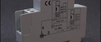
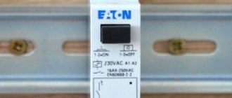
As a bonus, consider connecting using an outlet with a timer. In this case, the switching circuit works without a “stop” button. That is, in the presence of control voltage (from the timer), the electrical installation operates.
How to connect a push-button post to a magnetic starter
A magnetic starter (contactor) is used to start and stop the motor. It is also used to control a wide variety of loads (lighting, heating, etc.). The starter regulates the operation of devices that have remote control.
The principle of its operation is based on supplying operating voltage to an electromagnetic coil. After this, its core, attached to the contacts, is retracted, which leads to the closure of the contacts. After removing the load, the contacts open again.
Connecting the push-button control station
The magnetic starter has 4 pairs of contacts that close when the electrical device is triggered. The first three take part in voltage switching. The fourth pair is designed to apply a load to the coil at the moment the start button is released. At the top there are contacts (A1, A2), to which operating voltage is supplied. To improve ease of use, A2 is duplicated below. This is the right place to access.
The connection diagram assumes the use of a conventional push-button station equipped with “Stop” and “Start” buttons. Inside the post there are both normally open and closed contacts. The functionality of the contacts varies due to the difference in connection. After pressing the button, some contacts close (in the figure below - numbered 1 and 2), while others open (numbered 3 and 4). To give you an idea, let’s illustrate the description:
First, we connect the power wires to the main terminals of the three-phase starter. We take one phase and lead it to the post for connection to terminal 4 at the base of the “Stop” button. We stretch three wires between the post and the starter. From output 3 of the “Stop” button we stretch the wire to output 2 of the “Start” button. We connect two other wires to outputs 1, 2 of the “Start” button.
Returning to the starter, we connect the neutral conductor to A1. Next, we connect the wire from the push-button station (from output 1) to A2. When the post is started, the starter will close. The released “Start” should leave the starter on, and therefore we draw a conductor from the fourth pair of contacts. To the additional terminal A2 (at the bottom) we stretch the wire from the opposite terminal of the block contact. The entire set of connections will look something like this:
As a result, at the moment of startup, the current flows to terminal A2, which closes the coil. The starter fires. After releasing the “Start” button, the current bypasses this button and also reaches the coil through the switched-on block contact. The system starts working. After pressing the “Stop” button, we interrupt the supply via a block contact and open the starter. This circuit is relevant for powering an electric motor.
How to connect a three-phase motor via a magnetic starter
Power supply 380 V (three phases) is carried out in the same way, only there will be more power wires.
The contactor includes not one, but three phase lines. In this case, the control button is connected according to a similar circuit (as in the single-phase case).
The illustration shows a starter with a 380 V solenoid control coil. The control circuit is switched between any two phases. For safety, there is a thermal relay, the sensors of which can be located on one or several phase wires.
How to connect a 3-phase contactor with a 220 V starter winding? The circuit is similar, only the control circuit is switched between any of the phases and the neutral wire. The thermal relay works just as accurately, since its mechanism is tied to the temperature of the power cables.
How to change the direction of rotation of a motor using a starter
Three-phase electric motors make it possible to set the direction of rotation. There are many schemes for single-phase 220 V power supply. And for three-phase (380 V) switching, there is a connection diagram for a reversible magnetic starter.
The device consists of two independent circuits, with separate control of each group of contacts (pm1 and pm2). Each solenoid winding (PM1 and PM2) is controlled by its own button. In this case, there is only one stop key; it simply breaks the control circuit (as in a single starter). The connection of the input and output contacts of the second group is made with the so-called “phase shift”. In this case, the windings of the electric motor create torque on the shaft in the opposite direction.
The thermal relay is unchanged: their task is to open the starter in case of overload.
There is one feature:
To prevent a short circuit between phases, groups of contacts (pm1 and pm2) should not be closed at the same time. Therefore, they are mechanically placed on one rod, and purely physically cannot be connected to the power bus together. If you try to press the second button (while the first one is working), the power supply to the consumer will turn off.