Letter marking of wires
Standards for letter and color marking of wires
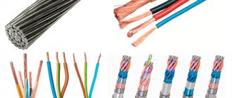
For household and industrial power lines, insulated wires with internal conductive conductors are used. Products differ depending on the color of the insulating coating and markings. The designation of phase and zero in electrics speeds up repair and installation work.
Marking of cables in electrical installations under voltage up to 1000 V is regulated by GOST R 50462-2009:
- in clause 6. 2.1 it is indicated that the neutral conductor is marked as N;
- clause 6.2.2. states that the protection wire with grounding is designated PE;
- in paragraph 6.2.12 it is said that in electrics L is a phase.
Understanding the markings simplifies installation work in commercial, residential and administrative buildings.
L – phase designation
Designation L and N in electrics
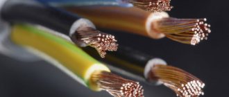
In an alternating current network, the phase wire is energized. Translated from English, the word Line means an active conductor, line, and is therefore marked with the letter L. Phase conductors must be covered with colored insulation, since, being exposed, they can cause burns, human injuries, fire or failure of various equipment.
N – alphabetic symbol of zero
The sign of a neutral or neutral working cable is N, from the abbreviation of the terms neutral or NULL. When drawing up a diagram, the zero switching terminals in a single-phase or three-phase network are marked this way.
The word “zero” is used only in the CIS countries; throughout the world the core is called neutral.
PE – grounding index
Grounding marking
If the wiring is grounded, the letter marking PE is used. In English, the meaning of Protective Earthing is translated as grounding wire. Clamps and contacts for switching with ground zero will be designated similarly.
Conductor insulation coating colors
It is necessary to color-code grounding, phase and neutral cables in accordance with the requirements of the PUE. The document establishes color differences for grounding in the electrical panel, as well as for zero and phase. Understanding the insulation color code eliminates the need to decipher letter markers.
Ground wire color
In the Russian Federation, the European standard IEC 60446:2007 has been in force since January 1, 2011. It notes that the grounding has only yellow-green insulation. If an electrical circuit is drawn up, the ground should be designated as PE.
There is a grounding core only in cables with 3 cores.
PEN conductors used in old buildings combine ground and neutral conductors. The insulating coating in this case has a blue grounding color and yellow-green cambrics at the connection points and ends of the wire. In some cases, the reverse marking was used - yellow-green color zeroing with blue tips.
The ground and neutral conductors of PEN cables are thinner than the phase conductors.
The organization of protective grounding is a prerequisite for creating an electrical network in residential and industrial buildings. Its necessity is indicated in the PUE and GOST 18714-81. Standards state that zero grounding should have the lowest resistance. To avoid confusion, use color markings for the cables.
Color designation of zero working contacts
Color of wires in electrical wiring
In order not to confuse where the phase is and where the zero is, instead of the letters L and N, they are guided by the colors of the cables. Electrical standards note that the neutral is blue, light blue, blue-white, regardless of the number of wires.
Zero can be designated by the Latin letter N, which is read as a minus in the diagram. The reason for reading is the participation of zero in the closure of the electrical circuit.
Phase wire colors
A phase is a live line that, if touched carelessly, can lead to electric shock. Novice craftsmen often have difficulty finding a cable. The phase is indicated by black, brown, cream, red, orange, pink, purple, gray and white.
The alpha phase index is L. It is used where the wires are not color coded. When connecting a cable to several phases, a serial number or Latin letters A, B, C are placed next to the letter L. The phase is also often marked as plus.
The phase wire cannot be blue, cyan, green or yellow.
Socket and plug
The hob must be connected using power sockets and plugs or a terminal box. Power sockets and plugs are designed for currents greater than 10 A, are made of special plastic, and may have a cover. The selection rule is simple: their rated current should be no less than the current of the machine. That is, to connect an electrical appliance up to 7.7 kW to a single-phase network, we take 32 A, for a three-phase network - 16 A.
What sockets and plugs for a hob might look like
There is no single standard, so the shape and location of the pins may be different, it is important that there is the required number of contacts and that the electrical characteristics match. It’s clear: it’s better to trust trusted brands rather than Chinese products.
You can connect the cable from the device and the power supply in the terminal box. This method is also called permanent connection, “direct” or “direct”. It is more reliable, but to turn off the stove you will have to go to the electrical panel and turn it off with a switch on the RCD or automatic circuit breaker.
Terminal box for three-phase network
For a three-phase connection, it is better to use a Schneider Electric 102x100x37 IP44 40A (KLK-5S) box. It's not cheap, but it's reliable and looks decent: you don't have to hide it. It can also be used for a 220 V network - a wire with a cross-section of 6 mm2 will fit into the terminals and the extra phases will simply be empty. To make the connection, the wires are inserted into the holes on the side, and they are tightened with bolts, the heads of which are visible in the photo.
As you can see, at the top there are three pairs of contacts for connecting phases (1,2,3). Below - for ground and neutral. The power cable is connected on one side, and from the electrical appliance on the other.
If you wish, you can save money and buy a simple block, but with good quality contacts and a separate mounting box with a lid.
Simpler option
The wires in such terminal blocks are connected simply: rings are formed from the stripped end of the copper wire (as in the photo above), into which small screws with plates are inserted. The wire is inserted into the socket, the contact is tightened with a screwdriver.
If the wire is stranded, it is problematic to make a ring out of it. Then you can use the tips (photo at the beginning of the article). They are crimped using pliers (can be replaced with pliers).
These are all the main points. Now connecting the hob yourself will not be a problem. The same rules apply when connecting other equipment of the same power. For less powerful ones, it will only be necessary to take a smaller cross-section of conductors and a lower nominal value of the machines.
The nuances of manual color marking
Color marking of wires using cambric
Manual marking is used when using wires of the same color in old buildings. Before starting work, a diagram with the color values of the conductors is drawn up. During the installation process, you can mark current-carrying conductors:
- standard cambrics;
- cambrics with heat shrinkage;
- insulating tape.
The rules allow the use of special marking kits. The installation points for markers to indicate zero and phase are indicated in the PUE and GOST. These are the ends of the wire and where it connects to the bus.
Specifics of marking a two-core wire
Heat shrink tube for wires
If the cable connection to the network has already been made, you can use an indicator screwdriver. The difficulty in using the tool lies in the inability to determine multiple phases. You will need to test them with a multimeter. To prevent confusion, you can color-code the electrical conductor:
- choose heat-shrinkable tubes or electrical tape to indicate zero and phase;
- work with conductors not along their entire length, but only at the junctions and joints.
The number of colors is determined by the scheme. The main thing when creating it is not to get confused, not to use yellow, green or blue markers for the phase. It can be marked in red or orange.
Three-wire wire marking
Using a multimeter, you can determine the location of the phase, zero, and grounding.
To find the phase, grounding, and zero in a three-wire wire, it is advisable to use a multimeter. It is set to alternating voltage mode and carefully touches the phase with probes, then touches the remaining cores. The tester's performance should be recorded and compared. In the phase-ground combination, the voltage will be lower than in the phase-zero combination.
After clarifying the lines, you can make markings. The corresponding colors will help you understand whether the phase is L or N. For zero it will be blue or blue, for plus it will be any other.
The procedure for marking a five-wire system
Electrical wiring from a three-phase network is carried out only with a five-core cable. Three conductors will be phase, one will be neutral, one will be protective ground. Color coding is applied in accordance with regulatory requirements. For protection, a yellow-green braid is used, for zero - blue or cyan, for phase - from the list of permitted shades.
How to mark combined wires
To simplify the wiring process, cables with two or four cores are used. The defensive line here connects to the neutral. The letter index of the wire is PEN, where PE denotes the grounding conductor, and N is the neutral conductor.
According to GOST, special color markings are used. The length of the combined cable will be yellow-green, and the tips and connection points will be blue.
Highlight the main points of problem areas with cambrics or electrical tape.
Wiring colors as a way to speed up installation
The correct coloring of the wiring speeds up the installation of electrical wiring.
Before GOST R 50462-2009 came into effect, cables were marked white or black. The phase and zero were determined when the control switch was turned off at the moment of power supply.
The use of color markers simplifies repair work, ensures safety and convenience. Based on the shade of the cables, the master will not spend much time connecting electricity to a house or apartment.
You can consider the meaning of color marking using the example of a lamp. If the lamp is changed and the zero and phase are reversed, there is a risk of injury or death from electric shock. When in electrics the designation L and N is made by color, the phase will go to the switch, and zero will go to the light source. The voltage will be neutralized, and you will be able to touch even a light bulb that is on.
Coloring phase
In cases where the electrical installation is installed using rigid metal busbars, the tires are painted with indelible paint in the following colors:
The color of the phases must be maintained throughout the entire device, but not necessarily over the entire surface of the bus. It is allowed to mark the phase designation only at the connection points. On a painted surface, you can duplicate the color with the “ ZhZK ” symbols for paint of the corresponding colors.
If tires are not accessible for inspection or work when there is voltage on them, then they may not be painted.
The color of phase wires connected to rigid busbars may not coincide with them in color, since there is a difference in the accepted designation systems for flexible conductors and rigid stationary distribution busbars.
Expert opinion
It-Technology, Electrical power and electronics specialist
Ask questions to the “Specialist for modernization of energy generation systems”
Pinout of wires by color: marking in electrical networks Control circuits operational circuits are buttons, fuses, coils of starters or contactors, contacts of intermediate and other relays, contacts of starters and contactors, voltage phase control relays, as well as connections between these and other elements. Ask, I'm in touch!